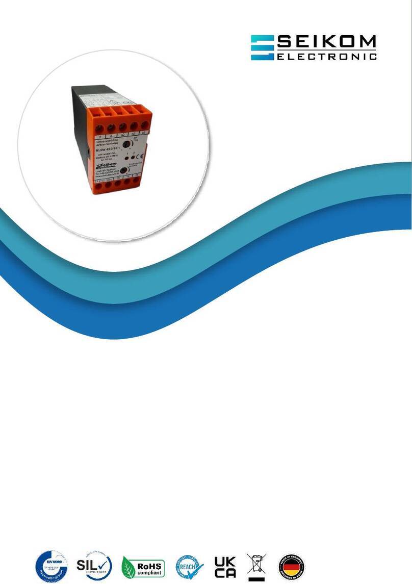
Air Flow Monitoring
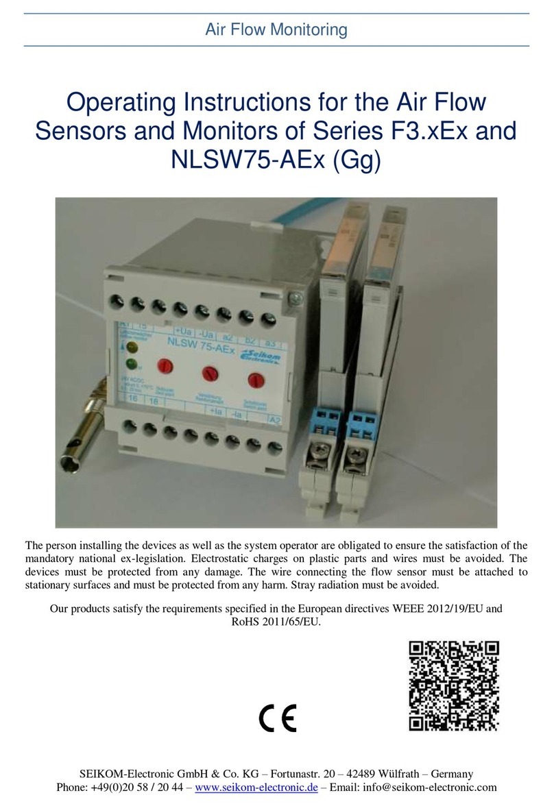
Operating Instructions for the Air Flow Sensors and Monitors of Series F3.xEx and NLSW75-AEx
SEIKOM-Electronic GmbH & Co. KG –Fortunastr. 20 –42489 Wülfrath –Germany
Phone: +49(0)20 58 / 20 44 –www.seikom-electronic.de –Email: info@seikom-electronic.com 5
i) The person performing the installation of the air flow sensors and their connection to the flow
monitors is responsible for their correct function and must ensure that they are eligible for their
intended use.
j) The intrinsically safe connection, including the air flow sensors, must be carried out via approved
flow monitors, which, if necessary, must be installed with suitable Zener-barriers or switching
amplifiers.
3. Installation and Start-Up
Depending on the IP protection class time intervals for cleaning of the equipment (accumulation of dust)
must be set. Additional important facts:
a) The product can be installed in zone 2 (Cat. 3G, EPL Gc) or in zone 1 (Cat. 2G, EPL Gb) in
intrinsically safe electrical circuits by professionals equally competent to qualified personnel
according to TRBS 1203.
b) The information provided on the label must be followed bindingly during installation.
c) The products can only be operated in ordinary industrial atmosphere. The manufacturer must be
contacted if the atmosphere contains aggressive components. In case of adverse ambient conditions,
the sensors need to be protected accordingly.
d) Usage of the devices is only permissible when they are fully mounted and connected in an intact
condition. Damages would enable a zone entrainment which must therefore be considered by the
operator. Usage of devices with damaged casing is not permitted.
e) The in this operating instructions defined permissible ambient conditions must be met, the products
must be protected from adverse ambient conditions.
f) Thermal radiation of other components and products must be considered.
g) The air flow sensors must be protected from impermissible inflow of liquids and/or pollution.
h) Tight or stuck parts, e. g. due to frost or corrosion, cannot be loosened with force if exposed to an
explosive atmosphere. Icing must therefore be avoided.
i) The air flow sensors can only be exposed to minor vibrations, see IEC 34-14.
j) To ensure the dissipation of electrostatic charges, national regulations must be considered.
k) Especially capacities that build up in an isolated manner must be avoided.
l) The flow sensor housing should be connected to the potential equalization electrostatically, a
threshold value of 1MΩis permissible.
m) Only Zener-barriers and switching amplifiers with Ex-area approved output circuits can be used. In
Europe the use within zone 1 requires an EC type examination for the relevant equipment, issued by
a for explosion protection appointed authority.
n) The power P0of all supply units combined must be lower or equal to the power Piof the air flow
sensors.
o) The supply voltage of the supply units must be lower or equal to the voltage Uiof the air flow
sensors.
p) The current Ioof all supply units combined must be lower or equal to the current Iiof the air flow
sensors.
q) For the installation of an intrinsically safe electrical circuit, a block diagram (system description) is
necessary, which must be provided by the builder or operator.
r) If a Zener-barrier is used, a potential equalisation between the grounding connection and the flow
sensor casing alongside the intrinsically safe electrical circuit must be ensured
s) The certificates including the therein defined special conditions must be considered.
t) Tight or stuck parts, e. g. due to frost or corrosion, cannot be loosened with force if exposed to an
explosive atmosphere.
u) The flow sensors cannot be used in facilities with cathodic corrosion protection. Although special
precautions might enable the use of the flow sensors in this special case, the manufacturer must be
contacted in any scenario. Parasitic currents cannot be discharged via the construction.
v) Within the area exposed to an explosion hazard the installation must comply with local regulations.


