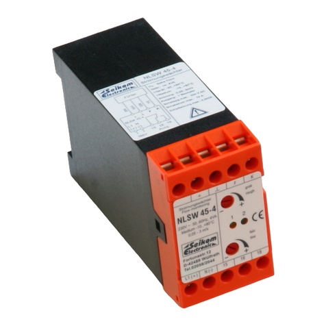
Seikom Electronic NLSW 45-3 Ex SIL2 User manual


Table of contents
Other Seikom Electronic Measuring Instrument manuals

Seikom Electronic
Seikom Electronic NLSW 45-3 SIL2 User manual

Seikom Electronic
Seikom Electronic NLSW 45-4 User manual

Seikom Electronic
Seikom Electronic RLSW4 User manual

Seikom Electronic
Seikom Electronic 77029 User guide
Seikom Electronic
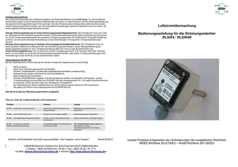
Seikom Electronic RLSW4 User manual

Seikom Electronic
Seikom Electronic RLSW 7 User manual
Seikom Electronic
Seikom Electronic F3.xEx Series User manual

Seikom Electronic
Seikom Electronic NLSW 45-3 SIL1 User manual

Seikom Electronic
Seikom Electronic NLSW 2a User manual

Seikom Electronic
Seikom Electronic RLSW 5A User manual
Seikom Electronic
Seikom Electronic F3 Ex SIL1 Series User manual

Seikom Electronic
Seikom Electronic NLSW45-6 User manual

Seikom Electronic
Seikom Electronic NLSW45-5 User manual
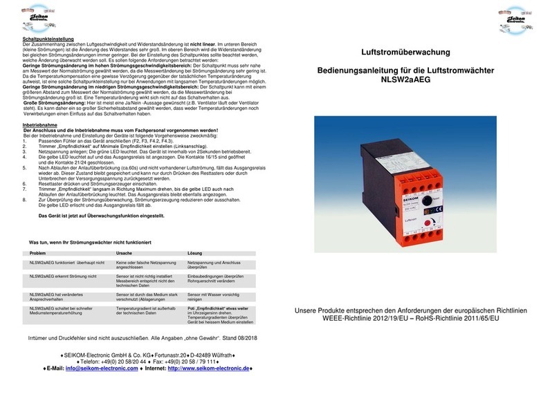
Seikom Electronic
Seikom Electronic NLSW2aAEG User manual

Seikom Electronic
Seikom Electronic NLSW45-6 User guide
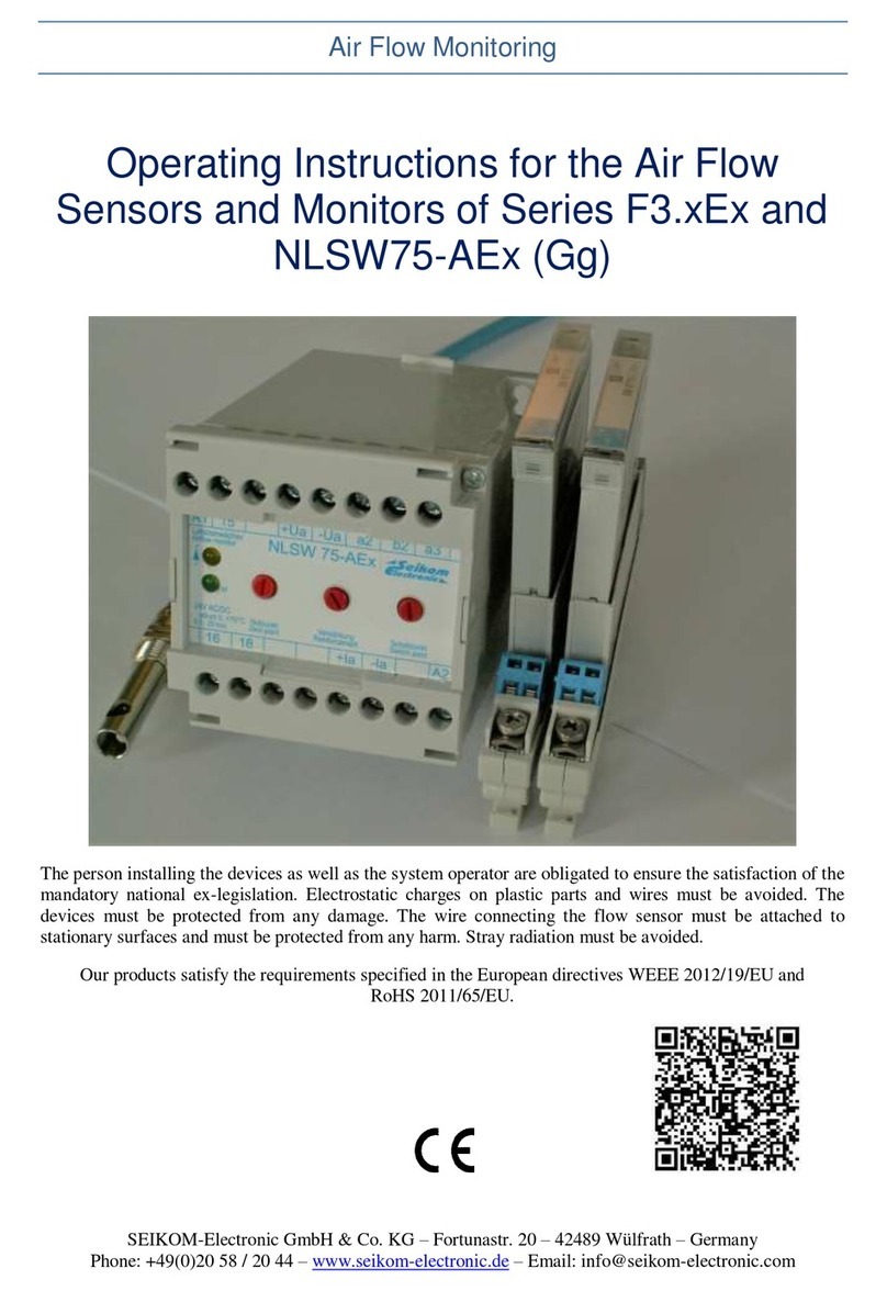
Seikom Electronic
Seikom Electronic NLSW75-AEx (Gg) User manual

Seikom Electronic
Seikom Electronic NLSW45-3Ex User manual

Seikom Electronic
Seikom Electronic RLSW 8 LCD User manual
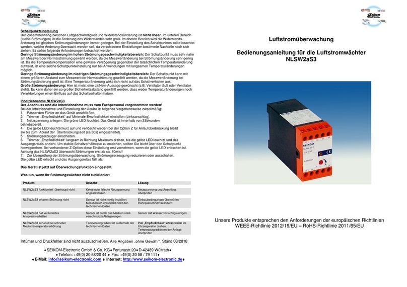
Seikom Electronic
Seikom Electronic NLSW2aS3 User manual
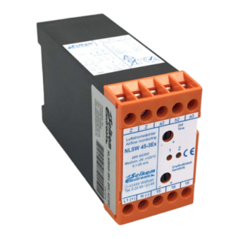
Seikom Electronic
Seikom Electronic NLSW45-3Ex User guide
Popular Measuring Instrument manuals by other brands

Brüel & Kjær
Brüel & Kjær 2239 B manual
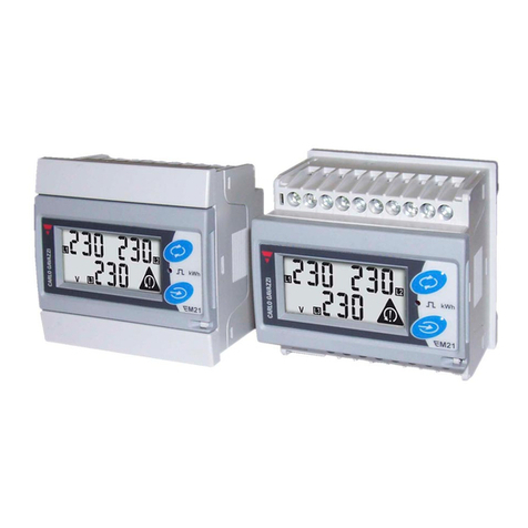
CARLO GAVAZZI
CARLO GAVAZZI EM 21 manual
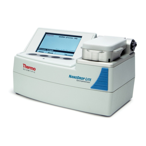
Thermo Scientific
Thermo Scientific Nanodrop Lite Quick reference guide
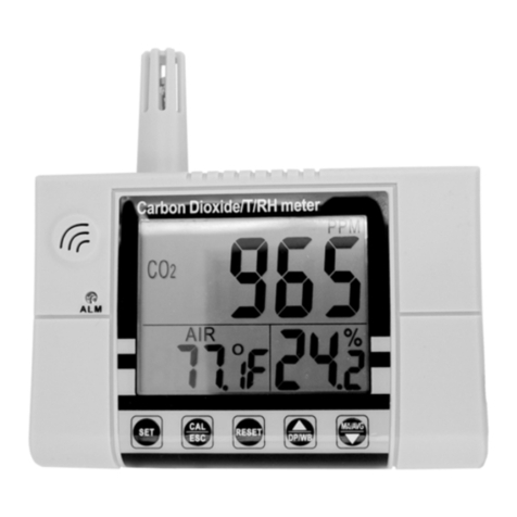
Spectrum
Spectrum 3445 product manual
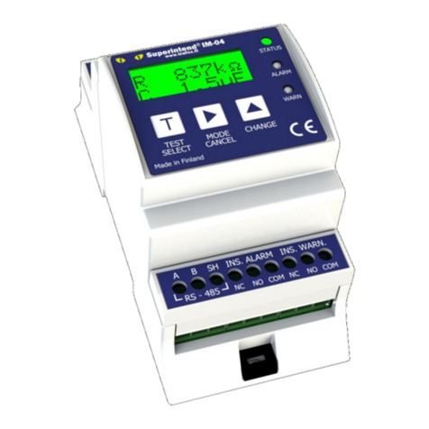
Trafox
Trafox SUPERINTEND IM-04DCCT Instructions for installation and use
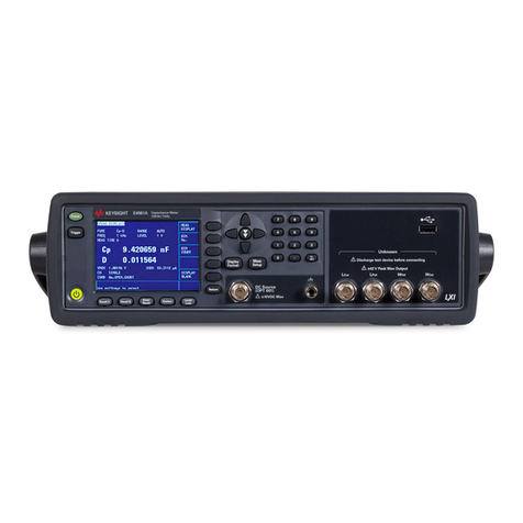
Keysight Technologies
Keysight Technologies E4981A Service guide
