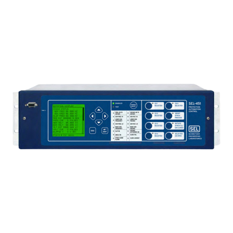
Sel SEL-451-6 User manual

Schweitzer Engineering Laboratories, Inc. SEL-451-6 Data Sheet
Protection, Automation, and Bay Control
System With Sampled Values or TiDL
Technology
Key Features and Benefits
The SEL-451-6 Protection, Automation, and Bay Control System With Sampled Values or TiDL®Technology integrates
bay control for breakers and disconnect switches with full automation and protection in one device.
➤High-Impedance Fault (HIF) Detection. The optional HIF detection element operates for small current ground
faults typically caused by downed conductors on surfaces such as earth, concrete or other poorly conductive
materials. HIF event data are made available in standard COMTRADE format.
➤Synchronism Check. Synchronism check can prevent circuit breakers from closing if the corresponding phases
across the open circuit breaker are excessively out of phase, magnitude, or frequency. The synchronism-check
function has a user-selectable synchronizing voltage source and incorporates slip frequency, two levels of maximum
angle difference, and breaker close time into the closing decision.
➤Reclosing. You can incorporate programmable reclosing of one or two breakers into an integrated substation
control system. Synchronism and voltage checks from multiple sources provide complete bay control.
➤Fault Locator. Utilities can efficiently dispatch line crews to quickly isolate line problems and restore service
faster.
➤Dual CT Input. You can combine currents within the relay from two sets of CTs for protection functions, but keep
them separately available for monitoring and station integration applications.
➤Primary Potential Redundancy. Multiple voltage inputs to the relay provide primary voltage input redundancy.
Upon loss-of-potential (LOP) detection, the relay can use inputs from an electrically equivalent source connected
to the relay.
➤Low-Energy Analog (LEA) Inputs. As many as six IEEE C37.92-compliant LEA voltage inputs can reduce costs
and save space.
SEL-451-6 Protection, Automation,
and Bay Control System

SEL-451-6 Data Sheet Schweitzer Engineering Laboratories, Inc.
2
➤Comprehensive Metering. The built-in, high-accuracy metering functions can improve feeder loading. Watt and
VAR measurements optimize feeder operation. Minimize equipment needs with full metering capabilities
including rms, maximum/minimum, demand/peak, energy, and instantaneous values.
➤Auxiliary Trip/Close Pushbuttons. These optional pushbuttons are electrically isolated from the rest of the relay.
They function independently from the relay and do not need relay power.
➤Bay Control. The relay provides bay control functionality with status indication and control for disconnect
switches. The relay features control for as many as two breakers and status indication of as many as three breakers.
Numerous predefined user-selectable mimic displays are available; the selected mimic appears on the front-panel
screen in one-line diagram format. The one-line diagram includes user-configurable labels for disconnect
switches, breakers, bay name, and display for as many as six analog quantities. The relay features SELOGIC
programmable local control supervision of breaker and disconnect switch operations.
➤Breaker Failure. High-speed (less than one cycle) open-pole detection logic reduces coordination times for critical
breaker failure applications. Apply the relay to supply breaker failure protection for all supported breakers. Logic
for breaker failure retrip and initiation of transfer tripping is included.
➤IEC 60255-149 Compliant Thermal Model. The relay can provide a configurable thermal model for the protection
of a wide variety of devices. This function can activate a control action or issue an alarm or trip when equipment
overheats as a result of adverse operation conditions. A separate resistance temperature detector (RTD) module is
required for this application.
➤Ethernet Access. The optional Ethernet card grants access to all relay functions. Use IEC 61850 Manufacturing
Message Specification (MMS) or DNP3 protocol directly to interconnect with automation systems. You can also
connect to DNP3 networks through a communications processor. Use File Transfer Protocol (FTP) for high-speed data
collection. Connect to substation or corporate LANs to transmit synchrophasors by using TCP or UDP internet protocols.
➤Serial Data Communication. The relay can communicate serial data through SEL ASCII, SEL Fast Message,
SEL Fast Operate, MIRRORED BITS®, and DNP3 protocols. Synchrophasor data are provided in either SEL Fast
Message or IEEE C37.118 format.
➤Automation. The enhanced automation features include programmable elements for local control, remote control,
protection latching, and automation latching. Local metering on the large front-panel LCD eliminates the need for
separate panel meters. Serial and Ethernet links efficiently transmit key information, including metering data, protection
element and control I/O status, synchrophasor data, IEC 61850 Edition 2 GOOSE messages, Sequential Events
Recorder (SER) reports, breaker monitoring, relay summary event reports, and time synchronization. Apply expanded
SELOGIC®control equations with math and comparison functions in control applications. Incorporate as many as
1000 lines of automation logic to accelerate and improve control actions.
➤Synchrophasors. You can make informed load dispatch decisions based on actual real-time phasor measurements
from relays across your power system. Record streaming synchrophasor data from the relay for system-wide disturbance
recording. Control the power system by using local and remote synchrophasor data.
➤Breaker and Battery Monitoring. You can schedule breaker maintenance when accumulated breaker duty
(independently monitored for each pole) indicates possible excess contact wear. The relay records electrical and
mechanical operating times for both the last operation and the average of operations since function reset. Alarm
contacts provide notification of substation battery voltage problems (as many as two independent battery monitors
in some SEL-400 series relays) even if voltage is low only during trip or close operations.
➤Digital Secondary Systems (DSS) Technologies. You can order the relay as either an SV subscriber relay or a
TiDL relay. DSS capable relays receive current and voltage information that is published by remote merging units
instead of standard PT and CT inputs. DSS technologies reduce copper cable lengths and associated installation
labor costs and improve the overall safety of the substation.
➤IEC 61850-9-2LE SV Relay. The SV subscriber relay can subscribe to current and voltage information that is
published by as many as seven remote SV merging units that are compliant with the IEC 61850-9-2LE guideline.
➤TiDL Relay. The TiDL relay can receive current and voltage information from as many as eight SEL-TMUs (TiDL
Merging Units) over direct point-to-point fiber-optic connections. The TiDL relay automatically synchronizes data
collection, alleviating the need or impact of an external clock on protection.
➤Selective Protection Disabling. The subscriber or TiDL relay provides selective disabling of protection functions
by using hard-coded logic or available torque-control equations in case of a loss of communications between your
merging unit and relay that results in the loss of relevant analog data.
➤Current Summation. The relay can combine multiple SV stream currents to simplify external wiring.

Schweitzer Engineering Laboratories, Inc. SEL-451-6 Data Sheet
3
➤Six Independent Settings Groups. The relay includes group logic to adjust settings for different operating conditions,
such as station maintenance, seasonal operations, emergency contingencies, loading, source changes, and adjacent
relay settings changes. Select the active group settings by control input, command, or other programmable conditions.
➤Software-Invertible Polarities. Inverting individual or grouped CT and PT polarities allows you to account for
field wiring or zones of protection changes. CEV files and all metering and protection logic use the inverted polarities,
whereas COMTRADE event reports do not use inverted polarities but rather record signals as applied to the relay.
➤Parallel Redundancy Protocol (PRP). PRP provides seamless recovery from any single Ethernet network failure.
The Ethernet network and all traffic are fully duplicated with both copies operating in parallel.
➤IEC 61850 Operating Modes. The relay supports IEC 61850 standard operating modes such as Test, Blocked,
On, and Off.
➤IEEE 1588, Precision Time Protocol (PTP). PTP provides high-accuracy timing over an Ethernet network.
➤Digital Relay-to-Relay Communications. MIRRORED BITS communications can monitor internal element conditions
between bays within a station, or between stations, using SEL fiber-optic transceivers. Send digital, analog, and
virtual terminal data over the same MIRRORED BITS channel.
➤Sequential Events Recorder (SER). The SER records the last 1000 events, including setting changes, startups,
and selectable logic elements.
➤Oscillography and Event Reporting. The relay records voltages, currents, and internal logic points at a sampling
rate as fast as 8 kHz. Offline phasor and harmonic-analysis features allow investigation of bay and system performance.
Time-tag binary COMTRADE event reports with high-accuracy time stamping for accuracy better than 10 s.
➤Digitally Signed Upgrades. The relay supports upgrading the relay firmware with a digitally signed upgrade file.
The digitally signed portion of the upgrade file helps ensure firmware and device authenticity after it is sent over a
serial or Ethernet connection.
➤Increased Security. The relay divides control and settings into seven relay access levels; the relay has separate
breaker, protection, automation, and output access levels, among others. Set unique passwords for each access level.
➤Rules-Based Settings Editor. You can communicate with and set the relay by using an ASCII terminal or use
Grid Configurator to configure the relay and analyze fault records with relay element response. Use as many as
200 aliases to rename any digital or analog quantity in the relay.

SEL-451-6 Data Sheet Schweitzer Engineering Laboratories, Inc.
4
Functional Overview
SV
The SEL-451-6 SV Subscriber Relay subscribes to data
streams that are published by merging units, such as the
SEL-421-7 SV Publisher or SEL-401 Protection, Auto-
mation, and Control Merging Unit. The SEL-421-7 SV
Publisher provides full backup protection while the
SEL-401 can provide basic directional overcurrent and
breaker failure protection in the absence of communica-
tion. Using the process bus, the SEL-421-7 SV Publisher
or SEL-401 can provide voltage and current information
to multiple relays that subscribe to SV. The data may be
synchronized using Precision Time Protocol (PTP).
TiDL
The SEL-451-6 TiDL Relay receives and automatically
synchronizes data streams from connected and commis-
sioned SEL-TMU devices. The TiDL technology does
not require an external time source for local relay protec-
tion functions.
Figure 1 Functional Overview
ENV
25
50BF 5150
50BF 5150
79
81
SEL-451-6
27 59
32 67
DSS Inputs
Process Bus
Mapped BK1
Currents
Mapped 52A1
Statuses
Mapped 52A2
Statuses
Mapped
Voltages
Mapped BK2
Currents
ANSI NUMBERS/ACRONYMS AND FUNCTIONS
25 Synchronism Check
27 Undervoltage
32 Over- and Underpower
50 Overcurrent
50BF Dual Breaker Failure Overcurrent
51 Time-Overcurrent
52PB Trip/Close Pushbuttons*
59 Overvoltage
67 Directional Overcurrent
79 Autoreclosing
81 (O, U) Over- and Underfrequency
ADDITIONAL FUNCTIONS
16 SEC Access Security (Serial, Ethernet)
85 RIO SEL MIRRORED BITS Communications
BRM Breaker Wear Monitor
DFR Event Reports
ENV SEL-2600 RTD Module*
HBL Harmonic Blocking
HIZ High-Impedance Fault Detection Arc Sense
Technology (AST)*
LGC SELOGIC Control Equations
LOC Fault Locator
MET High-Accuracy Metering
PMU Synchrophasors
RTU Remote Terminal Unit*
SBM Station Battery Monitor
SER Sequential Events Recorder
SIP Software-Invertible Polarities
* Optional Feature
Note: Both copper and fiber-optic Ethernet ports are available.
LGC
DFRBRM
MET PMU
SER
SBM
SIP
HBL HIZ
49
Five-port Ethernet card ordering option depicted.
4
EIA-232
2
Ethernet
Station Bus
(Ports 5C, 5D)
1
IRIG-B
2
Ethernet
Process Bus
(Ports 5A, 5B)
1
Ethernet
Enginnering
Access
(Port 5E)
16 S
E
C
Figure 2 SV Network
Process Bus
q
qTime synchronization
is required for SV
communications. Time
synchronization can be
done over a process
bus or station bus
Figure 3 SEL TiDL System
T-Protocol

Schweitzer Engineering Laboratories, Inc. SEL-451-6 Data Sheet
5
Protection Features
Overcurrent Elements
The SEL-451 includes four phase, four negative-
sequence, and four ground instantaneous overcurrent ele-
ments. The SEL-451 also includes six selectable operat-
ing quantity inverse-time overcurrent elements. You can
select the operating quantities from the following:
IA, IB, IC, MAX(IA, IB, IC), I1, 3I2, IG
where IA, IB, IC can be fundamental or rms quantities
from either circuit breaker or combined currents.
The time-overcurrent curves (listed in Table 1)have two
reset characteristic choices for each time-overcurrent
element. One choice resets the elements if current drops
below pickup for one cycle. The other choice emulates
the reset characteristic of an electromechanical induction
disc relay.
Directional Elements
The SEL-451 includes a number of directional elements
for supervision of overcurrent elements. The negative-
sequence directional element uses the same patented
principle proven in the SEL-351. This directional element
can be applied in virtually any application, regardless of
the amount of negative-sequence voltage available at the
relay location.
The following three directional elements working together
provide directional control for the ground overcurrent
elements:
➤Negative-sequence voltage-polarized directional
element
➤Zero-sequence voltage-polarized directional element
➤Zero-sequence current-polarized directional element
Our patented Best Choice Ground Directional Element
selects the best ground directional element for the system
conditions and simplifies directional element settings.
(You can override this automatic setting feature for spe-
cial applications.)
Communications-Assisted
Tripping Schemes
Use communications to improve tripping time for better
customer service. The SEL-451 is the ideal relay for use
in pilot-based tripping schemes. Enhanced MIRRORED
BITS communications with SEL fiber-optic transceivers
provide 3–6 ms relay-to-relay transmission time. Among
the schemes supported are the following:
➤Permissive overreaching transfer tripping (POTT)
➤Directional comparison unblocking (DCUB)
➤Directional comparison blocking (DCB)
Use the SELOGIC control equation TRCOMM to program
specific elements, combinations of elements, inputs, etc.,
to perform communications scheme tripping and other
scheme functions. The logic readily accommodates the
following conditions:
➤Current reversals
➤Breaker open at one terminal
➤Weak-infeed conditions at one terminal
➤Switch-onto-fault conditions
LOP Logic Supervises Directional
Elements
The SEL-451 includes logic to detect an LOP caused by
failures such as blown fuses, which can cause an incor-
rect operation in directional elements. Simple settings
configure the LOP logic to either block or force forward
ground and phase directional elements under these con-
ditions. The logic checks for a sudden change in positive-
sequence voltage without a corresponding change in pos-
itive- or zero-sequence current. Tests and field experi-
ence show that this principle is very secure and is faster
than the tripping elements.
HIF Detection
HIFs are short-circuit faults with fault currents smaller than
what a traditional overcurrent protective relay can detect.
The SEL-451 includes logic used to detect HIF signatures
without being affected by loads and other system operation
conditions. A running average provides a stable pre-fault
reference and adaptive tuning learns and tunes out feeder
ambient noise conditions. Decision logic differentiates an
HIF condition from other system conditions such as switch-
ing operations and noisy loads. As much as 40 minutes of
HIF activity is stored in high-resolution COMTRADE
Table 1 Time-Overcurrent Curves
U.S. IEC
Moderately Inverse Standard Inverse
Inverse Very Inverse
Very Inverse Extremely Inverse
Extremely Inverse Long-Time Inverse
Short-Time Inverse Short-Time Inverse

SEL-451-6 Data Sheet Schweitzer Engineering Laboratories, Inc.
6
format and a summary of HIF activity is available using
ASCII commands. View important HIF data from avail-
able metering commands.
Combined Current for Protection
Flexibility
In traditional relays, when protecting a line fed from two
breakers, such as a breaker-and-a-half system or double-
breaker system, you needed to combine the CT inputs
before connecting these inputs to the relay. The SEL-451
can accept separate inputs from two separate CTs and
mathematically combine the currents. This allows col-
lecting separate current metering and breaker monitor
information for each breaker. Breaker monitoring func-
tions for two breakers are done within one relay. Individ-
ual breaker currents allow for breaker failure functions
on a per-breaker basis within the SEL-451. Breaker diag-
nostic reports from the SEL-451 provide you compara-
tive breaker information that you can use for advanced,
proactive troubleshooting.
Custom Control Capabilities
Customize control capabilities, adding stability and secu-
rity to your system.
➤Use expanded SELOGIC control equations to create
advanced stability enhancements such as VAR-flow
controlled time undervoltage load shedding.
➤Combine frequency elements with voltage supervision
for added security with underfrequency load-shedding
systems.
Multifunction Reclosing With
Flexible Applications
The SEL-451 includes three-pole trip and reclose func-
tions for either one or two breakers (Figure 5). Synchro-
nism check is included for breaker control. Synchronizing
and polarizing voltage inputs are fully programmable
with dead line/dead bus closing logic, as well as zero-
closing-angle logic to minimize system stress upon
reclosing. Program as many as four reclose attempts.
Select leader and follower breakers directly, or use a
SELOGIC control equation to determine reclosing order
based on system conditions.
Figure 4 VAR-Flow Controlled Time Undervoltage Load
Shedding
Volt Drop pu
Trip Time
Time (s)
15
10
5
00 0.5 1

Schweitzer Engineering Laboratories, Inc. SEL-451-6 Data Sheet
7
Backup Protection
Add reliability and dependability by providing indepen-
dent backup protection without increasing relay count.
Use each SEL-451 to provide primary directional over-
current protection with backup nondirectional overcur-
rent protection on the adjacent feeder. For additional
flexibility, use the available I/O or MIRRORED BITS com-
munications to switch protection upon loss of one relay.
Additional Features
Front-Panel Display
The LCD shows event, metering, settings, and relay self-
test status information. The target LEDs display relay
target information as shown in Figure 7.
Figure 7–Figure 8 show close-up views of the front panel
of the SEL-451. The front panel includes a 128 x 128
pixel, 3" x 3" LCD screen; LED target indicators; and
pushbuttons with indicating LEDs for local control func-
tions. The asserted and deasserted colors for the LEDs
are programmable. Configure any of the direct-acting
pushbuttons to navigate directly to an HMI menu item,
such as events, bay display, alarm points, display points,
or the SER.
The LCD is controlled by the navigation pushbuttons
(Figure 8), automatic messages the relay generates, and
programmable analog and digital display points. The
rotating display scrolls through the bay screen, alarm
points, display points, and metering screens. Each dis-
play remains for an adjustable time (1–15 s) before the
display continues scrolling. Any message generated by
the relay because of an alarm condition takes precedence
over the rotating display.
Bay Control
The SEL-451 provides dynamic bay one-line diagrams
on the front-panel screen with disconnect and breaker
control capabilities for numerous predefined user-select-
able bay types. You can download the Grid Configurator
interface from selinc.com to obtain additional user-
selectable bay types. The bay control can control as
many as ten disconnects and two breakers, depending on
the one-line diagram selected. Certain one-line diagrams
provide status for as many as three breakers and ten dis-
connect switches. Operate disconnects and breakers with
Figure 5 Two-Breaker Reclosing With Synchronism Check
52-1
52-2
Line
Bus 2
Bus 1
79
25
Figure 6 Using Two Cross-Connected SEL-451-5 Relays
to Provide Primary and Backup Protection for Two Feeders
Figure 7 Factory-Default Status and Trip Target LEDs
(12 Pushbutton, 24 Target Option)
Figure 8 Front-Panel Display and Pushbuttons
03/15/01 GROUP 1
00:00:05.387
EVENT: BCG T
LOCATION: 48.47
FREQ: 60.00
SHOT: 3P=1
BK1 OPEN
BK2 CLOSED
EVENT SUMMARY 10002

SEL-451-6 Data Sheet Schweitzer Engineering Laboratories, Inc.
8
ASCII commands, SELOGIC control equations, Fast Oper-
ate Messages, and from the one-line diagram. The one-
line diagram includes user-configurable apparatus labels
and as many as 24 user-definable analog quantities.
One-Line Bay Diagrams
The SEL-451 offers a variety of preconfigured one-line
diagrams for common bus configurations. Once you select
a one-line diagram, you can customize the names for all
of the breakers, disconnect switches, and buses. Most
one-line diagrams contain analog display points. You can
set these display points to any of the available analog
quantities with labels, units, and scaling. The SEL-451
updates these values along with the breakers and switch
position in real time to give instant status and complete
control of a bay. The following diagrams demonstrate
some of the preconfigured bay arrangements available in
the SEL-451.
Programmable interlocks help prevent operators from incor-
rectly opening or closing switches or breakers. The SEL-451
not only prevents the operator from making an incorrect con-
trol decision, but can notify and/or alarm when an incorrect
operation is initiated.
Circuit Breaker Operations From
the Front Panel
Figure 9–Figure 12 are examples of some of the many
selectable one-line diagrams in the SEL-451. Select the
one-line diagram from the Bay settings. Additional set-
tings for defining labels and analog quantities are also
found in the Bay settings. One-line diagrams are com-
posed of the following:
➤Bay names and bay labels (bay labels available in
one-line diagrams 14, 17, 18, and 23. All other
one-line diagrams use the bay name.)
➤Busbar and busbar labels
➤Breaker and breaker labels
➤Disconnect switches and disconnect switch labels
➤Analog display points
Figure 13 shows the breaker control screens available
when the ENT pushbutton is pressed with the circuit
breaker highlighted as shown in Figure 13(a).
Figure 9 Breaker-and-a-Half
Figure 10 Ring Bus With Ground Switch
Figure 11 Double Bus/Double Breaker
Figure 12 Source Transfer Bus
BAYNAME
BK2
BK1
SW1 SW2
BK3
BAYLAB2BAYLAB1
BUSNAM1
BUSNAM2
ESCNAVIG
BAYNAME
6 ANALOGS
I:99999.9 A
V:99999.9 KV
P:99999.9 MW
Q:99999.9 MV
F:99.9 HZ
BAYLAB1
SW2
SW3
BK1
BK2
SW1
BAYLAB2
ESCNAVIG
BAYNAME
6 ANALOGS
I:99999.9 A
V:99999.9 KV
P:99999.9 MW
Q:99999.9 MV
F:99.9 HZ
BUSNAM1
SW2
SW3
BK1 BK2
SW1
BUSNAM2
ESCNAVIG
BAYNAME
BUSNAM1
BK1 BK2
BUSNAM2
BAYLAB1
I:99999.9 A
V:99999.9 KV
P:99999.9 MW
I:99999.9 A
V:99999.9 KV
P:99999.9 MW
ESCNAVIG

Schweitzer Engineering Laboratories, Inc. SEL-451-6 Data Sheet
9
Rack-Type Breakers Mosaics
The SEL-451 supports the display of rack-type (also
referred to as truck-type) circuit breakers. The rack-type
breakers have three positions: racked out, test, and
racked in. When in the test or racked-in positions, the
breaker can be displayed as open or closed. When racked
out, there is no breaker open/close display. The rack-type
breakers are a display-only functionality and do not
impact any circuit breaker control capabilities.
Status and Trip Target LEDs
The SEL-451 includes programmable target LEDs, as well
as programmable direct-action control pushbuttons/LEDs
on the front panel. Figure 7 shows these targets.
The SEL-451 features a versatile front panel that you can
customize to fit your needs. Use SELOGIC control equa-
tions and slide-in configurable front-panel labels to
change the function and identification of target LEDs
and operator control pushbuttons and LEDs. The blank
slide-in label set is included with the SEL-451. You can
use templates supplied with the relay or hand label sup-
plied blank labels and print label sets from a printer.
Alarm Points
You can display messages on the SEL-451 front-panel
LCD that indicate alarm conditions in the power system.
The relay uses alarm points to place these messages on
the LCD.
Figure 14 shows a sample alarm points screen. The relay
can display as many as 66 alarm points. The relay auto-
matically displays new alarm points while in manual-
scrolling mode and in autoscrolling mode. Assign the
alarm point messages by using SER Points settings. The
asterisk next to the alarm point indicates an active alarm.
Use the front-panel navigation pushbuttons to clear inac-
tive alarms.
Figure 13 Screens for Circuit Breaker Selection
Bus Labels
BAYNAME
Breaker
Highlighted
(a) Bay Screen
After three seconds,
re-display the previous screen
Press Enter with breaker
highlighted
BAYNAME
OPEN BREAKER
CLOSE BREAKER
OPEN
Bkrnam
PRESS TO ACTIVATE
(b) Breaker Control Screen
BUS 2
Dis 4
Bkr 1
Dis 3
Dis 1 Dis 2
BUS 1
BUS T
Bay Name
Disconnect
Switch Label
Disconnect
Switch Label
Disconnect
Switch Label
Analog
Quantities
Display
Breaker
Label
6 ANALOGS
I:99999.9 A
V:99999.9 KV
P:99999.9 MW
Q:99999.9 MV
F:60.000 HZ
ESCNAVIG
Bay not in
LOCAL Control!
Cannot issue
controls.
(c) LOCAL Bit Not Asserted
ESC
NAVIG
Figure 14 Sample Alarm Points Screen
*Unauthorized Access
*Xfmr Fan Fail
*Xfmr Heat Overload
ALARM POINTS
Press to acknldge

SEL-451-6 Data Sheet Schweitzer Engineering Laboratories, Inc.
10
Advanced Display Points
Create custom screens showing metering values, special
text messages, or a mix of analog and status information
with programmable display points. Figure 15 shows an
example of how you can use display points to show circuit
breaker information and current metering. You can create
as many as 96 display points. All display points occupy
only one line on the display at all times. The height of the
line is programmable as either single or double, as shown
in Figure 15. These screens become part of the autoscrolling
display when the front panel times out.
Communications Features
See Specifications on page 20 for specific supported protocols.
The relay offers the following communications features:
➤Four independent EIA-232 serial ports.
➤Access to event history, relay status, and meter
information from the communications ports.
➤Password-controlled settings management and
automation features.
➤SCADA interface capability, including FTP,
IEC 61850, DNP3 LAN/WAN (via Ethernet), and
DNP3 (via serial port). The relay does not require
special communications software. You only need
ASCII terminals, printing terminals, or a computer
supplied with terminal emulation and a serial
communications port.
➤Synchrophasor data at 60 message-per-second data
format.
Ethernet Card
The Ethernet card has five small form-factor pluggable
(SFP) ports.aPORT 5A and PORT 5B are reserved for the
process bus network. PORT 5C and PORT 5D are reserved
for the station bus network. The process and station bus
networks support PRP and fast failover redundancy
modes. PORT 5E operates on an isolated network with a
unique IP address making it ideal for engineering and
data access. All ports support 100 Mbps speeds. PORT 5A
and PORT 5B also support 1 Gbps speeds to satisfy poten-
tially large traffic requirements on the process bus. The
process bus, station bus, and engineering access net-
works use separate MAC addresses and are logically
delineated, including in the Configured IED Description
(CID) file.b
Use popular Telnet applications for easy terminal com-
munications with SEL relays and other devices. Transfer
data at high speeds for fast file uploads. The Ethernet
card communicates using FTP applications for easy and
fast file transfers.
Communicate with SCADA by DNP3 and other substa-
tion IEDs by using IEC 61850 Manufacturing Message
Specification (MMS) and GOOSE messaging.
Figure 15 Sample Display Points Screen
Circuit Breaker 1
--Closed--
DISPLAY POINTS
Circuit BK1 SF6 Gas
--Alarm--
Circuit Breaker 2
A PH= 119.6 A pri
SF6 ALARM
Figure 16 System Functional Overview
Automation
Over Ethernet:
Two Ethernet Ports
10/100BASE-T
100BASE-FX
To Remote SEL Relay
Using MIRRORED BITS
Spare
Front Port Local
Operator or
Engineering
Access
IEC 61850 or
DNP LAN/WAN Communications
Processor
Serial Communication:
Three Rear EIA-232 Ports
One Front EIA-232 Port
aSFP transceivers are not included with the card and must be ordered
separately. See selinc.com/products/sfp for a list of compatible SFP
transceivers.
bThis paragraph describes the five-port Ethernet card ordering option.
It does not apply to the four-port Ethernet card ordering option.

Schweitzer Engineering Laboratories, Inc. SEL-451-6 Data Sheet
11
Choose Ethernet connection media options for primary
and standby connections:
➤10/100BASE-T twisted pair networkc
➤100BASE FX fiber-optic network
➤1000BASE-X fiber-optic networkd
Telnet and FTP
Use Telnet to access relay settings, metering, and event
reports remotely by using the ASCII interface. Use FTP
to transfer settings files to and from the relay via the
high-speed Ethernet port.
DNP3 LAN/WAN
DNP3 LAN/WAN provides the relay with DNP3 Level 2
Outstation functionality over Ethernet. Configure DNP3
data maps for use with specific DNP3 masters.
PTP
The Ethernet card provides the ability for the relay to accept
IEEE 1588 PTPv2 for data time synchronization. PTP
support includes the Default, Power System, and Power
Utility Automation Profiles. When connected directly to
a grandmaster clock providing PTP at 1-second synchro-
nization intervals, the relay can be synchronized to an
accuracy of ±100 ns in the PTP time scale.
SNTP Time Synchronization
Use SNTP to synchronize relays to as little as ±1 ms with
no time source delay. Use SNTP as a primary time source,
or as a backup to a higher accuracy time input to the relay.
PRP
Use PRP to provide seamless recovery from any single
Ethernet network failure, in accordance with IEC 62439-3.
The Ethernet network and all traffic are fully duplicated
with both copies operating in parallel.
HTTP Web Server
The relay can serve read-only webpages displaying cer-
tain settings, metering, and status reports. The web server
also allows quick and secure firmware upgrades over
Ethernet. As many as four users can access the embedded
HTTP server simultaneously.
IEC 61850 Ethernet Communications
IEC 61850 Ethernet-based communication protocols
provide interoperability between intelligent devices within
the substation. Standardized logical nodes allow inter-
connection of intelligent devices from different manufac-
turers for monitoring and control of the substation.
Eliminate system RTUs by streaming monitor and con-
trol information from the intelligent devices directly to
remote SCADA client devices.
You can order the relay with IEC 61850 protocol for relay
monitor and control functions, including:
➤As many as 128 incoming GOOSE messages. You
can use the incoming GOOSE messages to control
as many as 256 control bits in the relay with <3 ms
latency from device to device depending on network
design. These messages provide binary control
inputs to the relay for high-speed control functions
and monitoring.
➤As many as eight outgoing GOOSE messages.
Configure outgoing GOOSE messages for Boolean
or analog data such as high-speed control and
monitoring of external breakers, switches, and other
devices. Boolean data are provided with <3 ms latency
from device to device depending on network design.
➤IEC 61850 Data Server. The relay equipped with
embedded IEC 61850 Ethernet protocol provides
data according to predefined logical node objects.
Each relay supports as many as seven unbuffered
MMS report client associations. Relevant Relay
Word bits are available within the logical node
data, so status of relay elements, inputs, outputs, or
SELOGIC control equations can be monitored.
cFour-port Ethernet card ordering option only.
dGigabit speeds are only available on PORT 5A and PORT 5B of the five-
port Ethernet card ordering option.
Figure 17 Example PTP Network
GPS

SEL-451-6 Data Sheet Schweitzer Engineering Laboratories, Inc.
12
➤As many as 256 virtual bits. Configure the virtual
bits within GOOSE messaging to represent a variety
of Boolean values available within the relay. These
bits that the relay receives are available for use in
SELOGIC control equations.
➤As many as 64 remote analog outputs. Assign the
remote analog outputs to virtually any analog quantity
available in the relay. You can also use SELOGIC
math variables to develop custom analog quantities
for assignment as remote analog outputs. Remote
analog outputs that use GOOSE messages provide
peer-to-peer transmission of analog data. Each relay
can receive as many as 256 remote analog inputs
and use those inputs as analog quantities within
SELOGIC control equations.
➤IEC 61850 standard operating modes. The relay
supports Test, Blocked, On, and Off. The relay also
supports Simulation mode for added flexibility.
MMS File Services
This service of IEC 61850 MMS provides support for file
transfers completely within an MMS session. All relay
files that can be transferred via FTP can also be transferred
via MMS file services.
MMS Authentication
When enabled via a setting in the Configured IED Descrip-
tion (CID) file, the relay requires authentication from any
client requesting to initiate an MMS session.
Architect Software
Use ACSELERATOR Architect SEL-5032 Software to
manage the IEC 61850 configuration for devices on the
network. This Windows-based software provides easy-
to-use displays for identifying and binding IEC 61850
network data among logical nodes that use IEC 61850-
compliant CID files. Architect uses CID files to describe
the data available in each relay.
Serial Communications
MIRRORED BITS Communications
The SEL patented MIRRORED BITS technology provides
bidirectional relay-to-relay digital communication.
Figure 18 shows two relays with SEL-2815 Fiber-Optic
Transceivers that use MIRRORED BITS communications.
MIRRORED BITS communications can operate simultane-
ously on any two serial ports. This bidirectional digital
communication creates additional outputs (transmitted
MIRRORED BITS) and additional inputs (received
MIRRORED BITS) for each serial port operating in the
MIRRORED BITS communications mode.
Communicated information can include digital, analog,
and virtual terminal data. Virtual terminal allows opera-
tor access to remote relays through the local relay. You
can use this MIRRORED BITS protocol to transfer infor-
mation between stations to enhance coordination and
achieve faster tripping.
Open Communications Protocols
The relay does not require special communications software. ASCII terminals, printing terminals, or a computer sup-
plied with terminal emulation and a serial communications port are all that is required. Table 2 lists a brief description of
the terminal protocols.
Figure 18 Integral Communication Provides Secure Protection, Monitoring, and Control as Well as Terminal Access to
Both Relays Through One Connection
Fiber-Optic Cable
SEL-2815 SEL-2815
Bus 1 Bus 2
1Transmission Line 2
Digital, Analog, and Virtual Terminal Data
Other
Relays
Other
Relays
TX
RX
SEL-400 Series Relay
TX
RX
SEL-400 Series Relay

Schweitzer Engineering Laboratories, Inc. SEL-451-6 Data Sheet
13
Automation
Flexible Control Logic and
Integration Features
Use the control logic to perform the following:
➤Replace traditional panel control switches
➤Eliminate remote terminal unit (RTU)-to-bay wiring
➤Replace traditional latching relays
➤Replace traditional indicating panel lights
Eliminate traditional panel control switches with 64 local
control points. Set, clear, or pulse local control points
with the front-panel pushbuttons and display. Program
the local control points to implement your control scheme
via SELOGIC control equations. Use the local control
points for such functions as trip testing, enabling/disabling
reclosing, and tripping/closing circuit breakers.
Eliminate RTU-to-bay wiring with 64 remote control
points per relay. Set, clear, or pulse remote control points
via serial port commands. Incorporate the remote control
points into your control scheme via SELOGIC control
equations. Use remote control points for SCADA-type
control operations (e.g., trip, close, settings group selection).
Replace traditional latching relays for such functions as
remote control enable with 64 latching control points.
Program latch set and latch reset conditions with SELOGIC
control equations. Set or reset the latch control points via
control inputs, remote control points, local control points,
or any programmable logic condition. The relay retains
the states of the latch control points after turning on fol-
lowing a power interruption.
Replace traditional indicating panel lights and switches
with as many as 24 latching target LEDs and as many as
12 programmable pushbuttons with LEDs. Define cus-
tom messages (i.e., BREAKER OPEN, BREAKER CLOSED,
RECLOSER ENABLED) to report power system or relay con-
ditions on the large format LCD. Control displayed mes-
sages with SELOGIC control equations by driving the
LCD via any logic point in the relay.
SELOGIC Control Equations With
Expanded Capabilities and Aliases
Expanded SELOGIC control equations put relay logic in
the hands of the engineer. Assign inputs to suit your
application, logically combine selected bay elements for
various control functions, and assign outputs to your
logic functions.
Programming SELOGIC control equations consists of
combining relay elements, inputs, and outputs with
SELOGIC control equation operators (Table 3). Any ele-
Table 2 Open Communications Protocol
Type Description
ASCII Plain-language commands for human and simple machine communications. Use for metering, setting, self-test
status, event reporting, and other functions.
Compressed ASCII Comma-delimited ASCII data reports. Allows external devices to obtain bay data in an appropriate format for
direct import into spreadsheets and database programs. Data are checksum protected.
Extended Fast Meter, Fast
Operate, and Fast SER
Binary protocol for machine-to-machine communications. Quickly updates communications processors, RTUs,
and other substation devices with metering information, bay element, I/O status, time-tags, open and close
commands, and summary event reports. Data are checksum protected. Binary and ASCII protocols operate
simultaneously over the same communications lines so that control operator metering information is not lost
while a technician is transferring an event report.
Ymodem Support for reading event, settings, and oscillography files.
Optional DNP3 Level 2
Outstation
DNP with point remapping. Includes access to metering data, protection elements, contact I/O, targets, SER,
relay summary event reports, and settings groups.
IEEE C37.118 Phasor measurement protocol.
MIRRORED BITS SEL protocol for exchanging digital and analog information among SEL relays and for use as low-speed termi-
nal connection.
IEC 61850 Ethernet-based international standard for interoperability between intelligent devices in a substation.
PRP PRP provides redundant Ethernet network capabilities for seamless operation in the event of loss to one network.
SNTP Ethernet-based SNTP for time synchronization among relays.
FTP and Telnet Use Telnet to establish a terminal-to-relay connection over Ethernet. Use FTP to move files in and out of the
relay over Ethernet.

SEL-451-6 Data Sheet Schweitzer Engineering Laboratories, Inc.
14
ment in the Relay Word can be used in these equations.
For complex or unique applications, these expanded
SELOGIC functions allow superior flexibility.
Use the relay alias capability to assign more meaningful
names to analog and Boolean quantities. This improves
the readability of customized programming. Use as many
as 200 aliases to rename any digital or analog quantity.
The following is an example of possible applications of
SELOGIC control equations that use aliases.
Add programmable control functions to your relay and
automation systems. New functions and capabilities enable
using analog values in conditional logic statements. The
following are examples of possible applications of
SELOGIC control equations with expanded capabilities.
➤Emulate a motor-driven reclose timer, including
stall, reset, and drive-to-lockout conditions.
➤Scale analog values for SCADA retrieval.
➤Initiate remedial action sequence based on load
flow before fault conditions.
➤Interlock breakers and disconnect switches.
➤Restrict breaker tripping in excessive duty
situations without additional relays.
➤Hold momentary change-of-state conditions for
SCADA polling.
Metering and Monitoring
Access a range of useful information in the relay with the
metering function. Metered quantities include fundamen-
tal primary and secondary current and voltage magni-
tudes and angles for each terminal. RMS voltage and
current metering is also provided. Fundamental phase
and real and reactive power, per-phase voltage magni-
tude, angle, and frequency are displayed in the metering
report for applications that use the relay voltage inputs.
Table 3 SELOGIC Control Equation Operators
Operator Type Operators Comments
Boolean AND, OR, NOT Allows combination of measuring units.
Edge Detection F_TRIG, R_TRIG Operates at the change of state of an internal function.
Comparison >, , =, <=, <, < >
Arithmetic +, –, *, / Uses traditional math functions for analog quantities in an easily programmable equation.
Numerical ABS, SIN, COS, LN, EXP,
SQRT, LOG
Precedence Control ( ) Allows multiple and nested sets of parentheses.
Comment #, (* *) Provides for easy documentation of control and protection logic.
=>>SET T <Enter>
1: PMV01,THETA
(assign the alias “THETA” to math variable PMV01)
2: PMV02,TAN
(assign the alias “TAN” to math variable PMV02)
=>>SET L <Enter>
1: # CALCULATE THE TANGENT OF THETA
2: TAN:=SIN(THETA)/COS(THETA)
(use the aliases in an equation)
Table 4 Metering Capabilities (Sheet 1 of 2)
Capabilities Description
Instantaneous Quantities
Voltages
VA, B, C (Y), VA, B, C (Z), V3V0, V1, 3V2
0–300 V with phase quantities for each of the six voltage sources available as a separate
quantity.
Currents
IA, B, C (W), IA, B, C (X),
IAL, IBL, ICL, (combined currents)
IGL, I1L, 3I2L (combined currents)
Phase quantities for each of the two current sources available as a separate quantity or
combined as line quantities.

Schweitzer Engineering Laboratories, Inc. SEL-451-6 Data Sheet
15
Event Reporting and SER
Event reports and SER features simplify post-fault analy-
sis and help improve your understanding of both simple
and complex protective scheme operations. These fea-
tures also aid in testing and troubleshooting relay settings
and protective schemes.
Oscillography and Event Reporting
In response to a user-selected internal or external trigger,
the voltage, current, and element status information con-
tained in each event report confirms relay, scheme, and
system performance for every fault. The relay provides
sampling rates as fast as 8 kHz for analog quantities in a
COMTRADE file format, as well as eight-sample-per-
cycle and four-sample-per-cycle event reports. The relay
stores as much as 3 seconds of 8 kHz event data. The
relay supports inclusion of user-configurable analogs in
the events. Reports are stored in nonvolatile memory.
Relay settings operational in the relay at the time of the
event are appended to each event report.
Each relay provides event reports for analysis with soft-
ware such as SEL-5601-2 SYNCHROWAVE®Event Soft-
ware. With SYNCHROWAVEEvent, you can display
events from several relays to make the fault analysis eas-
ier and more meaningful. Because the different relays
time-stamp the events with values from their individual
clocks, be sure to time synchronize the relay with an
IRIG-B clock input or PTP source to use this feature.
Event Summary
Each time the relay generates a standard event report, it
also generates a corresponding event summary. This is a
concise description of an event that includes the follow-
ing information:
➤Relay/terminal identification
➤Event date and time
➤Event type
➤Event number
➤Time source
➤Active settings group
➤Targets asserted during the fault
➤Current magnitudes and angles for each terminal
➤Pre-fault and fault calculated zero- and negative-
sequence currents
➤Voltage magnitudes and angles
➤Terminals tripped for this fault
Differential Metering
Currents
IA, B, C, I1, 3I2, 3I0
Local terminal/all
Remote Terminals
Differential Current
IA, B, C, I1, 3I2, 3I0
Local terminal/all
Remote terminals
Alpha Plane
k
alpha
Alpha plane ratio
Alpha plane angle
Power/Energy Metering Quantities
MW, MWh, MVAR, MVARh, MVA, PF,
single-phase and three-phase
Available for each input set and as combined quantities for the line.
Demand/Peak Demand Metering
IA, B, C, 3I2, 3I0Thermal or rolling interval demand and peak demand.
MW, MVAR, MVA, single-phase Thermal or rolling interval demand and peak demand.
MW, MVAR, MVA, three-phase Thermal or rolling interval demand and peak demand.
Synchrophasors
Voltages (Primary Magnitude, Angle)
VA, B, C (Y), VA, B, C (Z)
Primary phase quantities (kV) for each of the six voltage sources available.
Currents
IA, B, C (W), IA, B, C (X)
Primary phase quantities (A) for each of the six voltage sources available.
Frequency
FREQ
dF/dT
Frequency (Hz) as measured by frequency source potential inputs.
Rate-of-change in frequency (Hz/s).
Table 4 Metering Capabilities (Sheet 2 of 2)
Capabilities Description

SEL-451-6 Data Sheet Schweitzer Engineering Laboratories, Inc.
16
➤Recloser shot count at time of trigger (if applicable)
➤Fault location (if applicable)
➤Breaker status (open/close)
With an appropriate setting, the relay sends an event
summary in ASCII text automatically to one or more
serial ports each time an event report is triggered.
SV Reporting
The SV Subscriber includes a comprehensive report of
the SV communication stream. The ASCII command
COM SV displays statistics information from the sample
values stream to aid in troubleshooting.
SER
Use this feature to gain a broad perspective of relay ele-
ment operation. Items that trigger an SER entry are select-
able and can include as many as 250 monitoring points,
such as I/O change-of-state and element pickup/dropout.
The relay SER stores the latest 1000 events.
Analog Signal Profiling
The relay provides analog signal profiling for as many as
20 analog quantities. Select any analog quantity mea-
sured or calculated by the relay for analog signal profil-
ing. You can select signal sampling rates of 1, 5, 15, 30,
and 60 minutes through settings. The analog signal pro-
file report provides a comma-separated variable (CSV)
list that you can load into any spreadsheet or database for
analysis and graphical display.
SELOGIC enable/disable functions can start and stop sig-
nal profiling based on Boolean or analog comparison
conditions.
Substation Battery Monitor for DC
Quality Assurance
The relay measures and reports the substation battery
voltage for up to two battery systems. The SEL-411L,
SEL-421, SEL-451 support two battery monitors while
the SEL-487B, SEL-487E, and SEL-487V support one.
Each battery monitor supports programmable threshold
comparators and associated logic provides alarm and
control for batteries and chargers. The relay also pro-
vides dual ground detection. Monitor dc system status
alarms with an SEL communications processor and trig-
ger messages, telephone calls, or other actions.
The measured dc voltage is reported in the METER display
via serial port communications, on the LCD, and in the
event report. Use the event report data to see an oscillo-
graphic display of the battery voltage. Monitor the sub-
station battery voltage drops during trip, close, and other
control operations.
Breaker Contact Wear Monitoring
Circuit breakers experience mechanical and electrical wear
during each operation. Effective scheduling of breaker
maintenance takes into account the manufacturer’s pub-
lished data of contact wear versus interruption levels and
operation count.
➤Every time the breaker trips, the relay integrates
interrupted current. When the result of this integration
exceeds the threshold set by the breaker wear curve
(Figure 19), the relay can alarm via an output contact
or the optional front-panel display. With this
information, you can schedule breaker maintenance
in a timely, economical fashion.
➤The relay monitors last and average mechanical and
electrical interruption time per pole. You can easily
determine if operating time is increasing beyond
reasonable tolerance and then schedule proactive
breaker maintenance. You can activate an alarm
point if operation time exceeds a preset value.
The relay also monitors breaker motor run time, pole dis-
crepancy, and breaker inactivity.
Figure 19 Breaker Contact Wear Curve and Settings
kA Interrupted
(Set Point 1)
(Set Point 2)
(Set Point 3)
Breaker Manufacturer's
Maintenance Curve
Close to Open Operations

Schweitzer Engineering Laboratories, Inc. SEL-451-6 Data Sheet
17
Diagrams and Dimensions
Figure 20 SEL-451 Panel-Mount Front Panel
Figure 21 SEL-451-6 SV Subscriber Relay, Rear Panel
i7287a
RESET
TARGET
TRIP
ENABLED
SCHWEITZER
ENGINEERING
LABORATORIES
PORT F
ESC ENT
SEL-451
PROTECTION AUTOMATION CONTROL
GROUND
79 LOCKOUT
79 RESET
79 CYCLE
NEG–SEQ
VCY ONSOTF
VBY ON
TIME
COMM
INST
B FAULT
C FAULT
A FAU LT
LOP
51 TIMING
VAY ON
BKR MAINT
EXT TRIP
IRIG LOCK
BKR FAIL
VCZ ON
VBZ ON
VAZ O N
RECLOSE
ENABLED
REMOTE
ALT
SETTINGS
ENABLED
GROUND
EVENT
SUMMARY
ENABLED
BAY
TEST
DISPLAY
MODE
HOT LINE
TAG
DISPLAY
POINTS
SER
EVENTS
BREAKER
CLOSED
CLOSE
BREAKER
OPEN
TRIP
Five-port Ethernet card ordering option depicted.
PORT 1
PORT 2
EIA-232
1
PORT 3
9
1
9
1
9
TIME IRIG–B
BAY 2 BAY 3 BAY 4
BAY 1
48
47
46
45
44
43
42
41
40
39
38
37
36
35
34
33
32
31
30
29
28
27
26
25
24
23
22
21
20
19
18
17
16
15
14
13
12
11
10
09
08
07
06
05
04
03
02
01 B
200
B
200
i7287a
31
GND
302928
27
2625
+/H –/N
POWER
–
+
Vdc 2
+
Vdc 1
Z
MONITOR
–
OUT01 OUT02 OUT03 OUT04 OUT05 OUT06 OUT07 OUT08 OUT14 OUT15 IN01 IN02 IN03OUT09 OUT10 OUT11 OUT12 OUT13 IN04 IN05 IN06 IN07 IN08
ACT LNK
100M
PORT 5E
ACT LNK
PORT 5D
ACT LNK
PORT 5C
ACT LNK
ACT LNK
PORT 5B
100/1000M
PORT 5A

SEL-451-6 Data Sheet Schweitzer Engineering Laboratories, Inc.
18
Figure 22 SEL-451-6 TiDL Relay, 4U Rear Panel
Figure 23 Dimensions for Rack- and Panel-Mount Models
Five-port Ethernet card ordering option depicted.
PORT 1
PORT 2
EIA-232
PORT 3
1
9
1
9
1
9
TIME IRIG–B
BAY 2 BAY 3 BAY 4
BAY 1
48
47
46
45
44
43
42
41
40
39
38
37
36
35
34
33
32
31
30
29
28
27
26
25
24
23
22
21
20
19
18
17
16
15
14
13
12
11
10
09
08
07
06
05
04
03
02
01 B
200
B
200
i7287a
31
GND
302928
27
2625
+/H –/N
POWER
–
+
Vdc 2
+
Vdc 1
Z
MONITOR
–
OUT01 OUT02 OUT03 OUT04 OUT05 OUT06 OUT07 OUT08 OUT14 OUT15 IN01 IN02OUT09 OUT10 OUT11 OUT12 OUT13 IN03 IN04 IN05 IN06 IN07 IN08
ACT LNK
100M
PORT 5E
ACT LNK
PORT 5D
ACT LNK
ACT LNK
PORT 5C
ACT LNK
PORT 5B
100/1000M
PORT 5A
EN AL
PORT 6A
EN AL
PORT 6B
EN AL
PORT 6C
EN AL
PORT 6D
EN AL
PORT 6E
EN AL
PORT 6F
EN AL
PORT 6G
EN AL
PORT 6H
TiDL CONNECTIONS ONLY

Schweitzer Engineering Laboratories, Inc. SEL-451-6 Data Sheet
19
Models and Options
Consider the following options when ordering and con-
figuring the SEL-451-6.
➤DSS connector type
➢IEC 61850-9-2LE-compliant SV subscriber
relay
➢SEL TiDL relay with T-Protocol
➤Chassis size
➢4U (U is one rack unit—1.75 in or 44.45 mm)
➤Chassis orientation and type
➢Horizontal rack mount
➢Horizontal panel mount
➢Vertical rack mount
➢Vertical panel mount
➤Power supply
➢24–48 Vdc
➢48–125 Vdc or 110–120 Vac
➢125–250 Vdc or 110–240 Vac
➤Ethernet card options
➢Four-port Ethernet card with port combinations
of:
➣Four copper (10BASE-T/100BASE-TX)
➣Four fiber (100BASE-FX)
➣Two copper (10BASE-T/100BASE-TX) and
two fiber (100BASE-FX)
➢Five-port Ethernet card with small form-factor
pluggable (SFP) ports (100BASE-FX and
1000BASE-X)e
➤Communications protocols
➢Complete group of SEL protocols
(SEL ASCII, SEL Compressed ASCII, SEL
Settings File Transfer, SEL Fast Meter, SEL
Fast Operate, SEL Fast SER, resistance
temperature detectors (RTDs), Enhanced
MIRRORED BITS Communications, DNP3, and
Synchrophasors (SEL Fast Message and
IEEE C37.118 format)
➢Above protocols plus IEC 61850 Edition 2
Contact the SEL factory or your local Technical Service
Center for particular part number and ordering informa-
tion (see Technical Support on page 27). You can also
view the latest part number and ordering information on
the SEL website at selinc.com.
Table 5 Interface Board Information
Board Name Inputs Description Outputs Description
INT2 8 Optoisolated, independent, level-sensitive 13 Standard Form A
2 Standard Form C
INT4 18 Two sets of 9 common optoisolated, level-sensitive 6 High-speed, high-current interrupting, Form A
6 Optoisolated, independent, level-sensitive 2 Standard Form A
eAll ports support 100 Mbps speeds. PORT 5A and PORT 5B also sup-
port 1 Gbps speeds.

SEL-451-6 Data Sheet Schweitzer Engineering Laboratories, Inc.
20
Specifications
Note: Because the SEL-451-6 uses DSS, relay operating times are delayed.
For SV applications, operating times are delayed by the configured channel
delay, CH_DLY. See SV Network Delays on page 25 in the SEL-400 Series
Relays Instruction Manual for more details. For TiDL applications, the
operating times are delayed by a fixed 1 millisecond. Use caution when
setting relay coordination to account for this added delay.
Note: The metering and protection element accuracies specified for the
SEL-451-6 are valid only when using SEL merging units. For SV
applications, third-party SV publisher devices are supported but hardware
accuracies and analog filtering need to be considered to determine the effect
on SEL-451-6 SV Subscriber Relay performance.
Compliance
Designed and manufactured under an ISO 9001 certified quality
management system
FCC Compliance Statement
This equipment has been tested and found to comply with the limits for
a Class A digital device, pursuant to part 15 of the FCC Rules. These
limits are designed to provide reasonable protection against harmful
interference when the equipment is operated in a commercial
environment. This equipment generates, uses, and can radiate radio
frequency energy and, if not installed and used in accordance with the
instruction manual, may cause harmful interference in which case the
user will be required to correct the interference at his own expense.
UL Listed to U.S. and Canadian safety standards
(File E212775; NRGU, NRGU7)
CE Mark
RCM Mark
General
Frequency and Rotation
System Frequency: 50/60 Hz
Phase Rotation: ABC or ACB
Nominal Frequency Rating: 50 ±5 Hz
60 ±5 Hz
Frequency Tracking
(Requires PTs):
Tracks between 40.0–65.0 Hz
Below 40 Hz = 40 Hz
Above 65.0 Hz = 65 Hz
Maximum Slew Rate: 30 Hz per s
Power Supply
24–48 Vdc
Rated Voltage: 24–48 Vdc
Operational Voltage Range: 18–60 Vdc
Vdc Input Ripple: 15% per IEC 60255-26:2013
Interruption: 20 ms at 24 Vdc, 100 ms at 48 Vdc
per IEC 60255-26:2013
Burden
SV Relay: <35 W
TiDL Relay: <40 W
48–125 Vdc or 110–120 Vac
Rated Voltage: 48–125 Vdc, 110–120 Vac
Operational Voltage Range: 38–140 Vdc
85–140 Vac
Rated Frequency: 50/60 Hz
Operational Frequency Range: 30–120 Hz
Vdc Input Ripple: 15% per IEC 60255-26:2013
Interruption: 14 ms at 48 Vdc, 160 ms at 125 Vdc per
IEC 60255-26:2013
Burden
SV Relay: <35 W, <90 VA
TiDL Relay: <40 W, <90 VA
125–250 Vdc or 110–240 Vac
Rated Voltage: 125–250 Vdc, 110–240 Vac
Operational Voltage Range: 85–300 Vdc
85–264 Vac
Rated Frequency: 50/60 Hz
Operational Frequency Range: 30–120 Hz
Vdc Input Ripple: 15% per IEC 60255-26:2013
Interruption: 46 ms at 125 Vdc, 250 ms at 250 Vdc per
IEC 60255-26:2013
Burden
SV Relay: <35 W, <90 VA
TiDL Relay: <40 W, <90 VA
Control Outputs
Note: IEEE C37.90-2005 and IEC 60255-27:2013
Update Rate: 1/8 cycle
Make (Short Duration
Contact Current):
30 Adc
1,000 operations at 250 Vdc
2,000 operations at 125 Vdc
Limiting Making Capacity: 1000 W at 250 Vdc (L/R = 40 ms)
Mechanical Endurance: 10,000 operations
Standard
Rated Voltage: 24–250 Vdc
110–240 Vrms
Operational Voltage Range: 0–300 Vdc
0–264 Vrms
Operating Time: Pickup 6 ms (resistive load)
Dropout 6 ms (resistive load)
Short-Time Thermal Withstand: 50 A for 1 s
Continuous Contact Current: 6 A at 70°C
4 A at 85°C
Contact Protection: MOV protection across open contacts
264 Vrms continuous voltage
300 Vdc continuous voltage
Limiting Breaking
Capacity/Electrical
Endurance:
10,000 operations
10 operations in 4 seconds, followed by
2 minutes idle
Fast Hybrid (High-Speed High-Current Interrupting)
Rated Voltage: 48–250 Vdc
Operational Voltage Range: 0–300 Vdc
Operating Time: Pickup 0 µs (resistive load)
Dropout 8 ms (resistive load)
Short Time Thermal Withstand: 50 Adc for 1 s
Continuous Contact Current: 6 Adc at 70°C
4 Adc at 85°C
Contact Protection: MOV protection across open contacts
300 Vdc continuous voltage
Rated Voltage Resistive Break
Inductive Break
L/R = 40 ms (DC)
PF = 0.4 (AC)
24 Vdc 0.75 Adc 0.75 Adc
48 Vdc 0.63 Adc 0.63 Adc
125 Vdc 0.30 Adc 0.30 Adc
250 Vdc 0.20 Adc 0.20 Adc
110 Vrms 0.30 Arms 0.30 Arms
240 Vrms 0.20 Arms 0.20 Arms
Other Sel Control System manuals
Popular Control System manuals by other brands

Agilent Technologies
Agilent Technologies 7890 GC Preparation checklist

heat-timer
heat-timer SQ-Elite-8T Installation and operation instruction manual

Pilz
Pilz PSS u2 ES 4DO SR 0.5A operating manual

Partners
Partners PCMMP3 installation instructions

Crestron
Crestron AV2 Operation guide

Norac
Norac UC4 Total Control installation manual