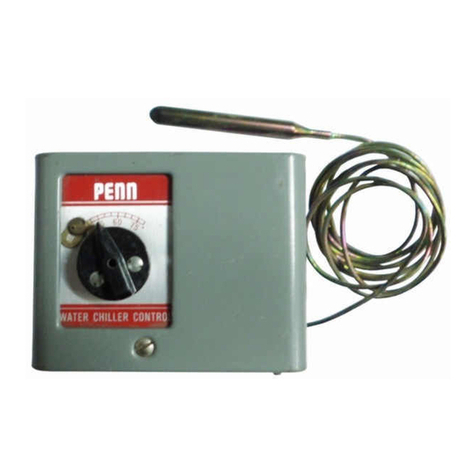
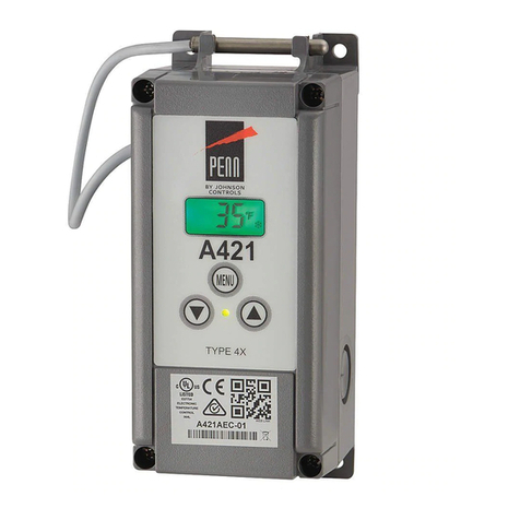
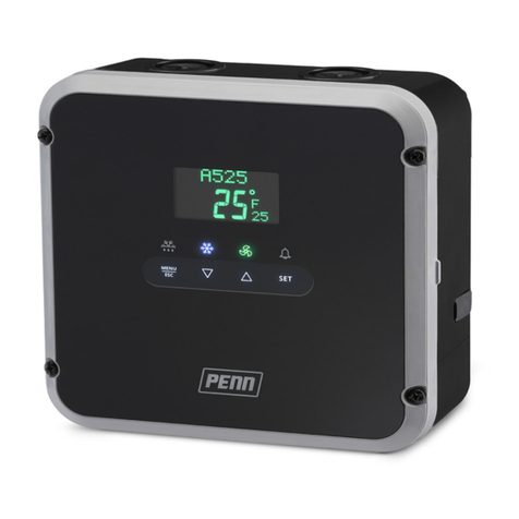
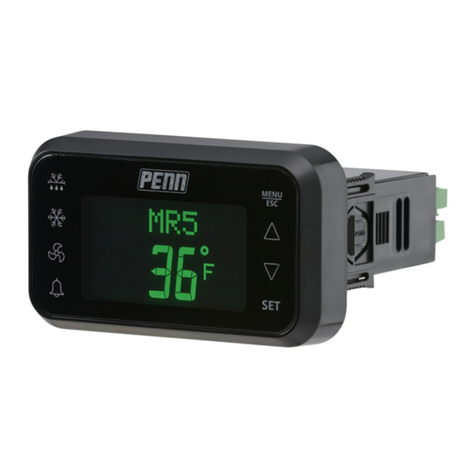
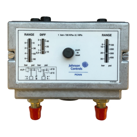
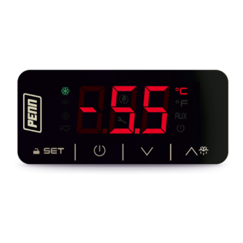
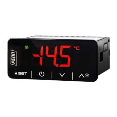
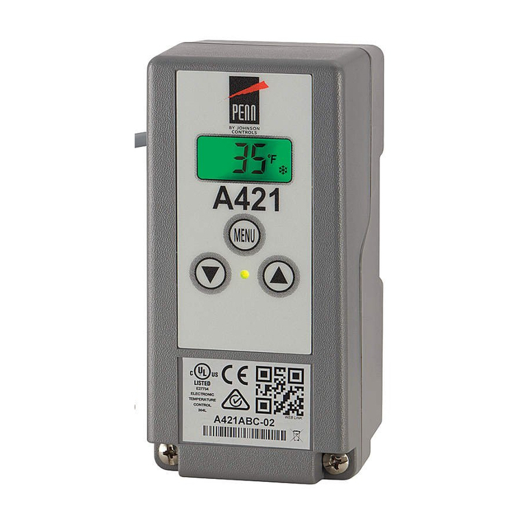
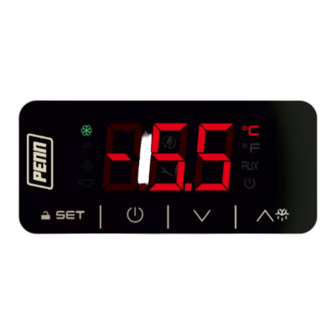
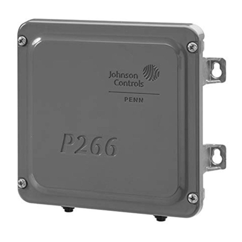
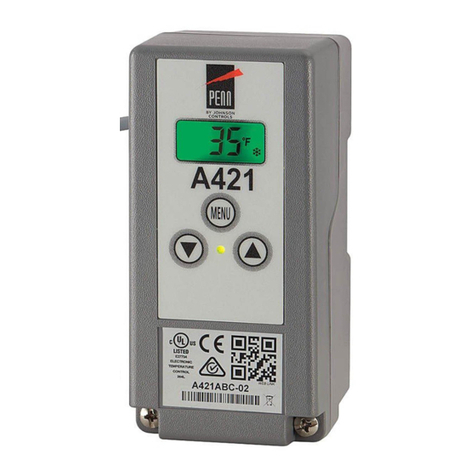
Penn A52 Series Service manual

A52x Series Electronic Refrigeration Controller with Adaptive Defrost Technical Bulletin
1
A52x Series Electronic Refrigeration Controller with
Adaptive Defrost
Technical Bulletin
Introduction
This document describes the features and functions of the A52x Electronic Refrigeration Controller with Adaptive
Defrost (A52x Controller), and provides guidelines and instructions to set up, adjust, and troubleshoot the
controller.
Overview
The A52x Controller provides refrigerated space control and defrost control for medium and low-temperature
refrigeration applications. The A525 Controller has five line-voltage relays to control the compressor, defrost
functions, high and low speed evaporator fans, and user-provided alarms. The controller can also control the
following functions:
• Resistive heat
• Hot-gas bypass
• Off-cycle defrost
• Two-speed evaporator fans
Refer to the A524/A525 Series Refrigeration Controller with Adaptive Defrost Installation Instructions (Part No. 24-
7664-3310) for information about relay wiring. The adaptive defrost feature adjusts the defrost schedule to the
minimum number of defrost intervals required to maintain peak efficiency, save energy, and maintain consistent
space temperature. The A52x Controller has an IP65 enclosure with holes in the enclosure base for wall-surface
mounting. An optional DIN Rail mounting kit (Part No. BKT524-1K) is also available.
IMPORTANT: Use of this product is subject to and constitutes your agreement to the End User License
Agreement set forth at www.johnsoncontrols.com/buildings/legal/digital LIT No. 12012405.
IMPORTANT: Use this A52x Refrigeration Controller only as an operating control. Where failure or malfunction
of the A52x Controller could lead to personal injury or property damage to the controlled equipment or other
property, additional precautions must be designed into the control system. Incorporate and maintain other
devices, such as supervisory or alarm systems or safety or limit controls, intended to warn of or protect against
failure or malfunction of the A52x Controller.
IMPORTANT : Utiliser ce A52x Refrigeration Controller uniquement en tant que dispositif de contrôle de
fonctionnement. Lorsqu'une défaillance ou un dysfonctionnement du A52x Régulateur risque de provoquer des
blessures ou d'endommager l'équipement contrôlé ou un autre équipement, la conception du système de
contrôle doit intégrer des dispositifs de protection supplémentaires. Veiller dans ce cas à intégrer de façon
permanente d'autres dispositifs, tels que des systèmes de supervision ou d'alarme, ou des dispositifs de
sécurité ou de limitation, ayant une fonction d'avertissement ou de protection en cas de défaillance ou de
dysfonctionnement du A52x Régulateur.
LIT No. 12012405
Issued April 2018

A52x Series Electronic Refrigeration Controller with Adaptive Defrost Technical Bulletin
2
Concepts
A52x User Interface
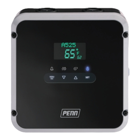
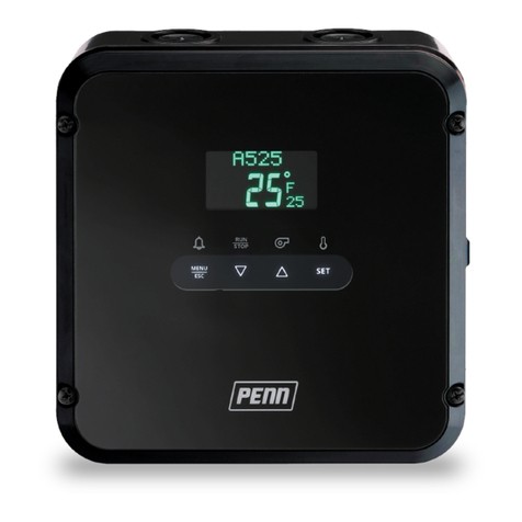
The A52x Controller has an LCD user interface with adjustable brightness that displays the system status and
setup information. Four status indicator icons that show the defrost, cooling, evaporator fan, and alarm features
provide a visual indication of the system status and alarms. You can use four touchpad keys to navigate the system
and to see detailed system information, change parameter settings, and respond to system alarms.The defrost and
alarm icons also function as touchpad keys to initiate unscheduled defrost cycles and clear system alarms.
Cleaning the A52x
Remove any loose debris from the controller. Wipe the exterior surface of the controller with a cloth and mild
detergent. Rinse the cloth with clean water and wipe the controller until it is clean. Dry the controller with a soft
cloth.
Notes:
• Do not use abrasive cleaning powders.
• Do not use abrasive cleaning pads or brushes.
• Do not use solvents or cleaning solutions that damage plastic.
Figure 1 shows the A52x Controller user interface. Figure 2 shows the controller’s status icons and touchpad keys.
Table 1 on page 3 describes the user interface behavior and user actions.
Figure 1: A52x Controller Interface

A52x Series Electronic Refrigeration Controller with Adaptive Defrost Technical Bulletin
3
Figure 2: A52x Display Fields, Icons, and Touchpad Keys
Figure 3 on page 4 shows the A52x Controller low voltage terminal block connections. Table 2 on page 4 describes
the A52x Controller’s low voltage terminal blocks, terminals, and wire sizes. Figure 4 on page 5 shows the A52x
Controller’s high voltage terminal block connections. Table 3 on page 5 describes the A52x Controller’s high
voltage terminal blocks, terminals, and wire sizes.
Table 1: A52x Controller Icons, Keys, Description, Behavior, and User Actions
Callout Item Name Description / Behavior / User-Actions
1 Defrost Icon The Defrost icon indicates the status of the defrost relay. A lit icon indicates that the defrost
relay is closed and the system is in defrost mode. When the Defrost icon is off, the defrost relay
is off and the system is not in defrost mode. To go to the manual defrost cycle start screen,
press and hold the Defrost icon for three seconds.
2 Cooling Icon The Cooling icon indicates the status of the compressor relay. A lit icon indicates that the
compressor is on. When the Cooling icon is off, the system is not in normal refrigeration mode;
it may be in defrost mode or system shutdown.
3 Evaporator
Fan Icon
The Evaporator Fan icon indicates the status of the Evaporator Fan. A lit icon indicates that
the evaporator fan relay or relays are closed. When the Evaporator Fan icon is off, the
evaporator fan relay is open.
4 Alarm Icon The Alarm icon indicates the presence of alarm conditions in the system. A lit icon indicates
that the alarm relay is closed. When the Alarm icon is off, the alarm relay is open. To
acknowledge any active alarms, tap the Alarm icon.
5 MENU/ESC
Key
To access the System Setup screens, press and hold the MENU/ESC key for three seconds on
the Home screen. To cancel any parameter value change in the current screen and return to the
previous setup screen or menu level, tap the MENU/ESC key in the System Setup screens.
6 Down and Up
Keys
To change the blinking parameter values in the System Setup screens, tap the Down or Up
keys. To scroll through the menu screens available in the current menu level, tap the Down or
Up keys.
7 SET Key To go to the next setup menu level, tap the SET key. To save the blinking parameter value or
menu selection and to go to the next setup screen, tap the SET key in any setup selection
screen.

A52x Series Electronic Refrigeration Controller with Adaptive Defrost Technical Bulletin
4
Figure 3: A52x Controller Low Voltage Terminal Block Connections
Table 2: A52x Controller Low Voltage Terminal Blocks, Terminals, and Wire Sizes
Terminal
Block Label
Terminal
Label
Description, Function, and Requirements Recommended
Wire Sizes
RS485
MODBUS
A + The RS485 Modbus communications terminal block is restricted to the
optional PENN Precision Superheat Controller (PSHC). Do not connect
any other Modbus device to these terminals.
0.20 to 0.30 mm2
(26 to 22 AWG)
Stranded wires
and twisted-leads
cable
B -
REF RS485 Modbus signal common or reference.
ANALOG
INPUT/
OUTPUT
Sn1 The main space temperature sensor. Connect either lead from the
sensor to Sensor 1 (Sn1). Connect the other lead to a common (C)
terminal.
Note: Sensor wires for the A52x Controller are not polarity sensitive.
0.30 to 1.50 mm2
(22 to 16 AWG)
Stranded wires
and twisted-leads
cable
C There are four low-voltage common terminals. All of the low-voltage C
terminals are connected together on the PC board.
Sn2 The evaporator temperature sensor. Connect either lead from the sensor
to Sensor 2 (Sn2). Connect the other lead to a C terminal.
Note: Sensor wires for A52x Controller are not polarity sensitive.
Sn3 Not available
UI4 Universal Input 4 can be configured as a 0–10 VDC analog input or dry
contact binary input. Connect a 0 to 10 VDC input or binary input to the
UI4 (+) terminal and a C (common/-) on the low voltage terminal block.
UI5 Universal Input 5 can be configured as a 0–10 VDC analog input or dry
contact binary input. Connect a 0 to 10 VDC input or binary input to the
UI5 (+) terminal and a C (common/-) on the low voltage terminal block.
AOI Note: Analog Output 1 (AO1) is not supported in the A525. Make no
connection to this terminal. The A524 Controller does not include
an analog output and does not have an AO1 terminal block.

A52x Series Electronic Refrigeration Controller with Adaptive Defrost Technical Bulletin
5
Figure 4: A52x Controller High Voltage Terminal Block Connections
Refrigeration Mode
Refrigeration mode is the normal operating mode of the A52x Controller. The system cycles the compressor on and
off, and operates the evaporator fans according to the setup selections to maintain the set point temperature in the
refrigerated space. See Figure 5 on page 6 for a common application of the A52x Controller. The controller exhibits
the following behaviors in refrigeration mode:
Table 3: A52x Controller High Voltage Terminal Blocks, Terminals, and Wire Sizes
Terminal
Block Label
Terminal
Voltages
Description, Function, and Requirements Recommended
Wire Sizes
90-240 VAC L1 Two terminals for supply power connection to the A525 Controller.
Requires 90 to 240 VAC; 15 VA, (0.25 A maximum).
0.75 to 2.50 mm2
(18 to 14 AWG)
L2/N
GND Earth ground connection terminal.
Compressor Two terminals for line-voltage, single-pole, single-throw (SPST), dry-
contact relay to the control compressor.
1.50 to 6.0 mm2
(16 to 10 AWG)
Alarm L1/LC The common (LC), normally-open (LNO), and normally-closed (LNC)
terminals for line-voltage, single-pole, double-throw (SPDT), dry-contact
relay to control the user-supplied alarm devices.
0.30 to 2.50 mm2
(22 to 14 AWG)
LNC
L2/N/LNO
LO-SPD AUX The A525 Controller includes two terminals for line-voltage, SPST, dry-
contact relay to control an auxiliary device such as a user-provided
alarm device or the low-speed on two-speed evaporator fans. The A524
Controller does not include this relay and terminal block.
0.30 to 2.50 mm2
(22 to 14 AWG)
HI-SPD Two terminals for line-voltage, SPST, dry-contact relay to control single-
speed evaporator fans or the high-speed on two-speed evaporator fans.
0.75 to 2.50 mm2
(18 to 14 AWG)
Defrost Two terminals for line-voltage, SPST, dry-contact relay to control
resistive defrost heater or bypass defrost solenoid.
1.5 to 6.0 mm2(16
to 10 AWG)
HVBIN Two line-voltage binary input terminals for use with the line-voltage
defrost temperature termination switch. These terminals require an
external power source to provide 120 to 240 VAC, 50/60 Hz activation
power when the external, user-supplied defrost termination switch
closes.
0.30 to 1.50 mm2
(22 to 16 AWG)

A52x Series Electronic Refrigeration Controller with Adaptive Defrost Technical Bulletin
6
• The fan icon indicates the evaporator fan relay status, which is either on or off.
• The defrost relay and icon remain off.
• The refrigeration icon indicates when the compressor is running.
• The LCD user interface displays the Home screen, which shows the system name, date, time, space
temperature, and set point.
Figure 5: Common Application of an A52x Controller
Defrost Mode
The selections you make for defrost type, defrost termination type, and evaporator fan behavior determine how
your refrigeration system operates during defrost mode. See Defrost Types and Defrost Termination Types for
more information. To manually start or stop a defrost cycle, press the Defrost icon for several seconds.
Table 4: Common Application of an A52x Controller
Callout Item Name
1Compressor/Condensing Unit
2QREV Expansion Valve
3Evaporator Fan with integrated Defrost Heater
4Ambient Temperature Sensor
5Defrost Temperature Sensor
6Precision Super Heat Controller (PSHC)
7A52x Controller
8Cold Room

A52x Series Electronic Refrigeration Controller with Adaptive Defrost Technical Bulletin
7
A defrost duration is the time period that the refrigeration system is in defrost mode and the system is melting ice
off of the evaporator coil. The defrost duration may include Drip Time. A defrost interval is defined as the time
between the start of a defrost cycle and the start of the next defrost cycle.
Figure 6: Defrost Intervals and Defrost Durations
Defrost Types
The A52x Controller provides defrost control for off-cycle defrost systems on medium temperature refrigeration
applications of 2C° to 7C° or 35F° to 45F°. The A52x Controller also provides defrost control for electric heat or hot
gas defrost systems on low temperature refrigeration applications of < 2°C or 35°F.
Off-Cycle Defrost
Off-Cycle (passive) Defrost does not use the defrost relay. Off-Cycle Defrost is the defrost type commonly used on
medium temperature refrigeration applications. Off-Cycle Defrost is not used on low temperature applications.
During Off-Cycle Defrost, refrigerant flow to the evaporator is interrupted. The evaporator fans remain on to move
air over the evaporator coil and melt any accumulated frost or ice. During Off-Cycle Defrost, the compressor relay
remains off for the defined defrost duration. Off-Cycle Defrost uses Timed Defrost Termination only. Off-Cycle
Defrost does not use an evaporator sensor or switch, and temperature defrost termination cannot be set up.
Electric Defrost
Electric Defrost uses electric resistive heating elements controlled by the defrost relay to melt the ice that
accumulates on the evaporator coil during normal cooling operation. The electric resistive heating elements are
typically embedded in or positioned near to the evaporator coil and drain pan. Electric Defrost is often used on low
temperature refrigeration applications. During Electric Defrost, the compressor relay remains off for the defrost
duration, the defrost relay is on, and the evaporator fan relay or relays are usually off. Electric Defrost cycles use
either temperature-based defrost termination or time-based defrost termination.
Hot Gas Defrost
Hot Gas Defrost systems use a bypass valve controlled by the defrost relay and extra refrigerant piping to
temporarily reroute the hot gas discharge from the compressor through the evaporator coil. The re-routed hot gas
melts the accumulated ice on the evaporator coil. Hot Gas Defrost is used on low and very low temperature
refrigeration applications. During the defrost duration, the compressor relay is on, the defrost relay is on, and the
evaporator fan relay or relays are usually off. Hot Gas Defrost cycles typically use temperature-based defrost
termination but may be set up for time-based defrost termination.
Defrost Termination Types
The A52x Controller can terminate the defrost durations based on time or temperature. Temperature termination
applications use a temperature sensor (Sn2) or a temperature switch mounted on the evaporator coil. On
applications that use temperature-based termination by sensor or switch, the maximum defrost duration value is
also defined in minutes. The defrost duration value terminates any defrost durations that do not reach the defined
defrost termination temperature.

A52x Series Electronic Refrigeration Controller with Adaptive Defrost Technical Bulletin
8
Time Based Defrost Termination
Time-based defrost control terminates the defrost duration when the user-defined maximum defrost duration
elapses. The defrost duration must be of sufficient length to remove all of the ice that accumulated on the
evaporator during the previous defrost interval. Timed Defrost Termination does not require a defrost termination
sensor or switch.
Temperature Sensor Defrost Termination
Temperature sensor defrost termination uses a defrost termination sensor (Sn2) mounted on the evaporator coil to
sense the coil temperature and terminate defrost at the user-selected termination temperature. The defrost
termination temperature value is the temperature at which the evaporator coil is clear of ice. Set the termination
temperature high enough to ensure that all of the accumulated ice has melted off the evaporator coil at the
termination temperature.
Temperature Switch Defrost Termination
You can also use a line-voltage temperature defrost termination switch connected to the high-voltage binary input
(HVBIN) terminals to terminate the defrost durations in your refrigeration application. The temperature termination
switch is mounted on the evaporator coil and it has a fixed temperature termination value. You do not need to set a
defrost termination temperature value during defrost setup. When 120 to 240 VAC is detected across the HVBIN
terminals, the A52x Controller terminates the defrost duration.
Time Based Termination Overrides Temperature Termination
The maximum defrost duration time period overrides both temperature-sensor and temperature-switch defrost
termination types, if the evaporator does not reach the termination temperature.The defrost duration terminates
when the evaporator reaches the selected defrost termination temperature or the maximum defrost duration
expires, whichever occurs first.
Defrost Schedule Types
Use the A52x Controller to schedule routine defrosts or use the adaptive defrost feature, which automatically
determines the optimal time to initiate the defrost cycles for your refrigeration system.
Scheduled Defrost
You can set up Scheduled Defrost as manual or automatic. You can schedule one to eight daily defrost cycles.
Using the manual setting, you set the start times for each daily defrost cycle. Using the automatic setting, you set
only two parameters; the number of daily defrost cycles and the real-time for the first scheduled defrost. The
system automatically calculates the daily schedule for the (equal-length) defrost intervals. You can use the manual
option to change one or more of the scheduled start times after you create a schedule.
Adaptive Defrost
Adaptive Defrost adjusts the defrost schedule to achieve a user-defined defrost duration. You set up the expected
defrost duration, the first defrost interval, and a defrost termination temperature. Initially, the system uses the first
defrost interval until it learns to adapt to the existing conditions. The Adaptive Defrost system adjusts the length of
the defrost interval so that the expected defrost duration coincides with the time that the evaporator reaches the
termination temperature. See
Adaptive Defrost Setup Parameters
for more information. For Adaptive Defrost to
take place, mount the Sn2 defrost sensor or the HVBIN defrost termination switch on the evaporator. The defrost
sensor or switch determines when the defrost duration is complete.
Compressor and Evaporator Fan Start Delays
You can set up four time delay features on the A52x Controller to control the compressor and evaporator fan
operation:
• Compressor Anti-Short Cycle Delay
A52x Series Electronic Refrigeration Controller with Adaptive Defrost Technical Bulletin
9
• Evaporator Fan Drip-Time Delay
• Evaporator Fan Temperature Delay
• Evaporator Fan Time Delay
When the A52x Controller is in a delay period, the delay type and the minutes left in the delay scroll across the
Message Field at the top of the display.
Anti-Short Cycle Delay
Anti-Short Cycle Delay (ASD) maintains the compressor relay off or open for a period of time after the relay cycles
off. This delay prevents the compressor from cycling back on quickly after it has cycled off. Select from 0 to 12
minutes for the Anti-Short Cycle Delay. See Figure 7.
Figure 7: Anti-Short Cycle Delay (ASD) Overriding Load Demand to Maintain Compressor Relay Off
Evaporator Fan Drip-Time Delay
Evaporator Fan Drip-Time Delay holds the compressor relay and the evaporator fan relays off (open) after the
defrost duration terminates. The user-selected drip-time delay allows the evaporator coil to shed additional water
and reduces the moisture that blows into the refrigerated space when the evaporator fans start. Select from 0 to 10
minutes for the Evaporator Fan Drip-Time Delay after the defrost duration terminates. The Evaporator Fan Drip-
Time Delay is not available for Off Cycle (passive) Defrost. See Figure 8 on page 10.
Evaporator Fan Temperature Delay
Evaporator Fan Temperature Delay holds the evaporator fan relay or relays off (open) after the defrost termination,
drip-time delay, and compressor start in cooling mode. This temperature-based evaporator fan delay allows the
evaporator coil to cool down and freeze any moisture before the evaporator fan or fans start. This delay reduces
the moisture and warm air that is blown into the refrigerated space. Select from 20F° to 35F° for the Evaporator
Fan Temperature Delay. See Figure 8 on page 10.
Evaporator Fan Time Delay
Evaporator Fan Time Delay holds the evaporator fan relays off (open) after defrost termination, drip-time delay, and
compressor restart in cooling mode. This time-based evaporator fan delay allows the evaporator coil to cool down
and freeze any moisture before the evaporator fan or fans start. This delay reduces the water and warm air that is
blown into the refrigerated space. The Evaporator Fan Time Delay works with the Evaporator Fan Temperature
Delay. If the evaporator coil reaches the evaporator fan temperature value before the time delay, the fan turns on. If
the time delay expires first and the coils are not at the temperature value, the fan turns on. Select a time delay from
0 to 15 minutes to allow the evaporator to freeze any remaining moisture, before the evaporator fans turn on.

A52x Series Electronic Refrigeration Controller with Adaptive Defrost Technical Bulletin
10
Figure 8: Example of the A52x Controller Relay States During Defrost Duration, Drip Time Delay, and
Evaporator Fan Delay
System Setup Parameters
The System Setup parameters define the basic system attributes, the hardware features, and hard-wired
components of your refrigeration system.
The first step in setting up an A52x Controller for your refrigeration system requires entering the System Setup
parameters. After the System Setup parameters are defined to your system’s requirements, only the setup screens
and parameters that are required to set up the system’s operation are available for set up.
System Setup parameters include the following features:
• Time and date
• Defrost type
• Defrost termination type
• Evaporator fan type
• Sensor type
• Units of temperature (Celsius or Fahrenheit)
• Display brightness and touchpad sound
• System name
In the System Setup screens, you can create an access password, download controller firmware updates, and also
set up the Quick Response Expansion Valve/Precision Superheat Controller (QREV/PSHC) monitoring and control
features.
Time and Date Setup
The Date/Time setup screens guide you through the setup of the following features:
• Time Format (12 or 24 hours)
• Time (hours, minutes, and AM or PM)
• Date Format (DMY or MDY)
On
Off
Off
On
Off
Compressor
Relay
Defrost
Relay
LO/AUX
(Fan) Relay
On
Off
On
Off
Off
Defrost
Duration
Drip Time
Delay
Evap Fan Delay
(Cool Down)
N orm al C ooling
M ode
Off
Off
Defrost
Ter m ination
Drip Time
Ends
Evap Fan Delay
Ends
TIME
Off
Load
Demand
Satisfied

A52x Series Electronic Refrigeration Controller with Adaptive Defrost Technical Bulletin
11
• Date (day, month, and year)
• Automatic Daylight Saving Time change over.
Sensor Setup
The A52x Controller requires the Sn1 cooling temperature sensor to monitor and control the cooling temperature in
the refrigerated space. Temperature-termination defrost applications and the Adaptive Defrost feature requires
either a Sn2 defrost termination sensor or a HVBIN defrost termination switch mounted on the evaporator coil.
The A52x Controller can use two types of sensors. In North America, all standard A52x Controller models ship with
two A99B-type temperature sensors. In Europe, the TS-6340 Negative Temperature Sensor (NTC) is available for
use. The sensors are set up independently; Sn1 and Sn2 do not have to be the same sensor type.
To set up the sensors on an A52x Controller, select the sensor type and the sensor offset in the System Setup
screens. The sensor offset allows you to offset the sensed temperature -5C° to 5C° or -5F° to 5F°. For example, if
you apply a -3°F offset, the actual sensed value of 30°F displays and controls as 27°F.
Evaporator Fan Setup
Select either a single-speed evaporator fan or a two-speed evaporator fan. The HI-SPD relay controls single-speed
evaporator fans. The LO-SPD/AUX relay and the HI-SPD relay control two-speed EC evaporator fans. When you
control single-speed fans with the HI-SPD relay, the LO-SPD/AUX relay is available to control an auxiliary device.
QREV/PSHC Setup
The A52x Controller is designed to communicate with the Johnson Control/PENN Quick Response Expansion
Valve (QREV) and Precision Super Heat Controller (PSHC). If the refrigeration system uses a QREV/PSHC, you
can monitor the QREV status, adjust the superheat set point, and change the refrigerant type on the PSHC to
match the refrigeration system’s refrigerant type. The QREV/PSHC status screens display the superheat, the
evaporator outlet temperature and pressure, the current valve state, and the PSHC firmware version.
Evaporator Fan Control
Evaporator fan behavior depends on the following conditions:
• Whether the evaporator fan is one-speed or two-speed
• Whether the system’s mode of operation is refrigeration or defrost
• The selected evaporator set up options in the Refrigeration and Defrost setup screens
Evaporator Fan Operation in Refrigeration Mode
In normal refrigeration mode, you can set a single-speed evaporator fan to run continuously or to cycle on and off
with the compressor. See Figure 9 on page 12. You can set a two-speed evaporator fan to run continuously at high
speed. See Figure 10 on page 13. You can also cycle between low-speed and high-speed. See Figure 11 on
page 13.

A52x Series Electronic Refrigeration Controller with Adaptive Defrost Technical Bulletin
12
Figure 9: Compressor and Lo/Aux Relay States for Single Speed Evaporator Fan Operation in Normal
Refrigeration Mode: Continuous On Fan or Cycling Fan with Compressor
Figure 10: Compressor, Lo/Aux, and Hi-Spd Relay States for Two Speed Evaporator Fan Operation in
Normal Cooling Mode: Continuous High Speed Fan
Figure 11: Compressor, Lo/Aux, and Hi-Spd Relay States for Two Speed Evaporator Fan Operation in
Cooling Mode Set Up for Low Speed Fan when Compressor is Off, High Speed when Compressor is On
On
Off
On
Off Off
On
Off
On
Off
On
Off Off
On
Off
On
Compressor Relay
HI-SPD R elay
1-Speed Evap Fan
(On C ontinuous)
HI-SPD R elay
1-Speed Evap Fan
(Cycles with
Compressor Relay)
Time

A52x Series Electronic Refrigeration Controller with Adaptive Defrost Technical Bulletin
13
Evaporator Fan Operation in Defrost Mode
The Evaporator Fan Drip-Time Delay, Evaporator Fan Temperature Delay, and Evaporator Fan Time Delay settings
affect the behavior of the Evaporator Fan in defrost mode and post-defrost mode. You can set up the post-defrost
evaporator fan behavior with the Evaporator Fan Delay After Defrost feature. The delay time period is 0 to 15
minutes. This feature does not apply if the controller is set to an off-cycle defrost.
Adaptive Defrost Setup Parameters
Expected Defrost Duration
Expected Defrost Duration is an estimate of the time the system requires to fully defrost the evaporator coil and to
reach the defrost termination temperature after a defrost interval. When you set up the Adaptive Defrost feature,
you enter the number of minutes for the Expected Defrost Duration. During operation and changing load
conditions, actual defrost durations may vary in length from your defined Expected Defrost Duration. When this
occurs, the system adjusts the defrost schedule.
Defrost Interval
Defrost Interval is an estimate of the number of hours between the start of consecutive defrost cycles. You enter
the expected Defrost Interval time in hours for the first defrost interval. The Adaptive Defrost feature shortens or
lengthens the Defrost Interval to reach the defrost termination temperature in the expected defrost duration. This
value provides a starting point for the adaptive defrost algorithm.
If the system reaches the defrost termination temperature before the expected defrost duration elapses, Adaptive
Defrost lengthens the next defrost interval. If the system reaches the defrost termination temperature after the
expected defrost duration time elapses, Adaptive Defrost shortens the next defrost interval.
Maximum Time Between Defrosts
Maximum Time Between Defrosts defines the maximum number of hours for any adaptive defrost interval. If the
system calculates a defrost interval that is greater than your defined maximum time, the controller ignores the
calculation and starts the next defrost duration at your defined maximum time.
Minimum Time Between Defrost
Minimum Time Between Defrosts defines the minimum number of hours for any adaptive defrost interval. If the
system calculates a defrost interval that is less than your defined minimum time, the Controller ignores the
calculation and starts the next defrost duration at your defined minimum time.
Blackout Period
You can schedule a daily blackout period for Adaptive Defrost applications, which prevents the occurrence of
defrost cycles during the defined blackout period. Blackout periods are typically scheduled for a regular, predictable
period of high cooling demand. To establish a blackout period for adaptive defrost, you must set up the Blackout
Start Time and Blackout parameters in the Defrost Setup menu flow.
•Blackout Start Time: This is the time at which the blackout period begins. The adaptive defrost algorithm does
not schedule any defrosts from the start to the end of the blackout period. Edit the real-time value to the time at
which the blackout period starts. The real-time value depends on the Time Format type selected in the Time/
Date screens in the System Setup menu flow.
•Blackout Duration: This is the number of hours that you add to the Blackout Start Time to form the blackout
period. The blackout period refers to the time interval during which no defrosts occur. Select the number of
minutes for your preferred blackout period duration. The duration starts at the Blackout Start Time.

A52x Series Electronic Refrigeration Controller with Adaptive Defrost Technical Bulletin
14
Universal Inputs and Alarms
Universal Input Modes
You can set each of the universal inputs to one of the modes in Table 5. When you select an input mode, one or
more control actions become associated with that mode.
Note: The system defines alarm actions separately from control actions. The selection of a particular input mode
may affect the list of available alarms. For example, Door Open Too Long becomes a potential alarm only
after you define the input as Door Open.
Setting Up Universal Input Modes
You can set each of the two universal inputs to one of these modes. When you configure an input mode, you must
specify if the input is a binary or an analog input. You then indicate what level of input equates to the TRUE
condition.
Table 5: A52x Universal Input Modes and Control Actions
Mode Control Action when condition is TRUE
None The state of the universal input has no effect on the A52x control.
Refrigerant Leak System Shutdown. The system remains shut down as long as the Refrigerant Leak condition
persists. A system shutdown takes priority over the normal control of the compressor, defrost,
and fan relays.
Man In Room You can select one of the following options for this input mode:
• Normal Control indicates that relays R1-R4 are unaffected.
• System Shutdown. This option takes priority over the normal control of the compressor,
defrost, and fan relays.
• Low Speed Fan, if running at High Speed. This option becomes available only if the
control is configured with the two-speed fan option. This takes priority over the normal
control of the fan relays. This option is available on the A525 Controller only.
• Energize Auxiliary Relay. This option becomes available only if the two-speed fan option
is not used. This option is available on the A525 Controller only.
Door Open You can select one of these options for this binary input mode:
• Normal Control indicates that R1-R4 are unaffected.
• Low Speed Fan. This option becomes available only if the control is configured with the
two speed fan option. This option takes priority over the normal control of the fan relays.
This option is available on the A525 Controller only.
• Shut off cooling.
• Energize Auxiliary Relay if the two speed fan option is not used. This option is available
on the A525 Controller only.
Emergency Switch
(Wall switch)
The system shuts down when it detects an input change from False to True. The system
remains shut down until the switch clears. A system shutdown takes priority over the normal
control of the compressor, defrost, and fan relays.
Table 6: A52x Universal Inputs and Mode Selections
Universal Input Mode Selection Binary or Analog True State (binary) True State (analog)
1None, not used
Refrigerant Leak
Man in Room
Door Open
Emergency Switch
BIN / ANA OPEN / CLOSED > nnn (user enters voltage)
2BIN / ANA OPEN / CLOSED > nnn (user enters voltage)

A52x Series Electronic Refrigeration Controller with Adaptive Defrost Technical Bulletin
15
Alarm Setup Parameters
Alarm Actions
• Piezo: If enabled, the piezo energizes.
• Alarm Relay: The alarm relay energizes when any alarm condition is TRUE. The alarm relay de-energizes
when you acknowledge the alarm locally or when the condition is no longer TRUE.
• Local UI: The local UI lights the alarm icon when any alarm condition is TRUE or requires
acknowledgment.
Alarm Settings
You must set these parameters for each alarm:
• Threshold: Each alarm may have a specific level, units, and range. For example, temperature alarms
expect Fahrenheit or Celsius values to set the alarm threshold. The Door Open alarm expects a time
duration. A binary input expects a 1 or 0, or an Open or Closed selection to indicate the alarm state.
• Piezo: Enabled or Disabled.
• Delay: This time is represented in minutes. The alarm condition must remain TRUE for the required
number of minutes before an actual alarm sounds. If the condition clears before the number of minutes
elapses, no alarm action initiates. If you set the delay to zero, the alarm triggers immediately.
• Auto Clear: Select a latching alarm or a self-clearing alarm. The latching alarm requires you to
acknowledge an alarm at the A52x Controller. The alarm icon remains lit, the alarm relay energizes, and
the piezo sounds (if enabled) until you acknowledge the alarm, even if the alarm condition is no longer
TRUE. A self-clearing alarm is an alarm that no longer identifies itself as TRUE if the underlying alarm
condition clears.
• Re-Alarm Interval: This time is represented in minutes. If you acknowledge the alarm and the alarm relay
deactivates but the alarm condition persists for this number of minutes, the alarm relay reactivates.
Alarm vs Warnings
The alarm set up includes a delay parameter. When an alarm condition crosses the alarm threshold, the alarm
does not occur until after the delay period. The alarm warning condition is active in this situation. A lit yellow alarm
icon indicates an alarm warning. Alarm warnings do not cause the alarm relay to energize and the system does not
add an alarm to event log.
Cooling Shutdown
Cooling Shutdown is a specific action that can occur when one of the two Universal Input modes receives an
external signal. The controller turns off the compressor and the fan when the system receives an external signal.
Table 7: List of Alarms and Alarm True Conditions
Alarms Alarm TRUE Condition
High Temperature Alarm The Sensor 1 temperature is greater than the high temperature alarm value that you defined for a
period of time equal to or greater than the alarm delay.
Low Temperature Alarm The Sensor 1 temperature is less than the low temperature alarm value that you defined for a
period of time equal to or greater than the alarm delay.
Sensor Failure Sensor 1 is in a state of failure.
Sensor Failure Sensor 2 is in a state of failure.
Door Open Alarm The door is open for a period of time equal to or greater than the value that you defined.
Man in Room Alarm A person is in the room for a period of time equal to or greater than the value that you defined.
Refrigerant Leak Alarm The refrigerant leak detector indicates a leak. This may be a voltage level that you defined.
Emergency Shutdown Emergency shutdown activates when a person trapped inside a cold room flips a switch.

A52x Series Electronic Refrigeration Controller with Adaptive Defrost Technical Bulletin
16
System Shutdown
A system shutdown takes priority over the normal control of the compressor, defrost, and fan relays. It can happen
if an alarmed condition such as man-in room, refrigerant leak or emergency switch is activated. An active system
shutdown state means that all outputs are set to off, excluding the alarm output. This state can be entered by
detection of a refrigerant leak, if enabled, or a Universal Input that is configured to provide this signal.
Detailed Procedures
Setting Up the A52x Controller
Set up the physical components and features of the A52x Controller in the System Setup screens. The selections
and values you enter in the System Setup screens define the characteristics and operation of your refrigeration
system on the A52x Controller.
Note: The gray setup screens indicate setup selections that are available based on previous setup selections.
After you define the system setup parameters in the A52x Controller for your system, the setup screens that do not
apply to your selections become unavailable when you set up the cooling and defrost parameters. The A52x
Controller ships with factory default selections and values in the system screens. In most applications, you must
change some of the factory default selections and values to meet your system’s specific cooling and defrost
requirements. See Figure 12 for the high-level work flow for setting up the A52x Controller for your refrigeration
system.
Figure 12: High-Level Setup Work Flow for the A52x Controller
1 - System Setup
Define the physical and operational
characteristics of your refrigeration system .
2 - Refrigeration Setup
Define the operational characteristics,
behaviors, and values for normal cooling
mode.
3 - Defrost Setup
Define the operational characteristics,
behaviors, and values for the defined defrost
mode.
4 - Universal Inputs Setup
Define the type and behavior of the
optional universal inputs.
5 - Alarm Setup
Define the type and behavior of the optional
alarms generated by the controller.
See Setting Up the Refrigeration
Setup Screens on page 24
See Setting Up the Defrost Cycle on
page 25
See Setting Up the Universal Inputs
on page 28
See Setting Up the Alarm Setup 1 of
2on page 29
See Setting Up the System Setup
Screens on page 20

A52x Series Electronic Refrigeration Controller with Adaptive Defrost Technical Bulletin
17
Navigating the High-Level Status and Setup Start Screen
To scroll through the high-level Status and Setup Start screens, tap the DOWN and UP keys.
SN1: COOLING TEMPSYSTEM STATUS
SET SET
SETPOINT
SET
REFRIGERATION
SETUP SET SET
QREV/PSHC :
SUPERHEAT
QREV/PSHC STATUS
SET SET
DATE/TIME
SET
SYSTEM SETUP
SET SET
DEFROST
DURATION SET
DEFROST SETUP
SET SET
UI 4
SET
UNIVERSAL INPUT S
SET SET
SN 1: HIGH TEMP
ALARM SET
ALARM SETUP
SET SET
CONFIG FILE
EXPORT SET
FILE
SET SET
WELCOME TO A525
SYSTEM NAME
15oF
10
MENU/ESC
The WELCOME screen displays when the A52x Controller powers on, and then changes to
the HOME screen.
The HOME screen displays the system name, the date, the time of day, the temperature at SN1, and
the setpoint value. To return to the SYSTEM STATUS START screen and the other high-level menu
start screens, press MENU/ESC.
To scroll through and view the SYSTEM STATUS screens, press SET in the
SYSTEM STATUS screen. See Viewing the System Status Screens for
more information.
To scroll through and view the QREV/PSHC STATUS screens, press SET
in the QREV/PSHC STATUS start screen. See Viewing the QREV/PSHC
Status Screens for more information. Note: The QREV/PSHC STATUS
screens are available only if a QREV is installed on the system.
To scroll through and set up the SYSTEM SETUP screens, press SET in
the SYSTEM SETUP start screen. See Setting Up the System Setup
Screens for more information.
To scroll through and set up the REFRIGERATION SETUP screens, press
SET in the REFRIGERATION SETUP start screen. See Setting Up the
Refrigeration Setup Screens for more information.
To scroll through and set up the DEFROST SETUP screens, press SET in
the DEFROST SETUP start screens. See Setting Up the Defrost Setup
Screens for more information.
To scroll through and set up the UNIVERSAL INPUTS screens, press SET
in the UNIVERSAL INPUT setup start screen. See Setting Up the
Universal Input Screens for more information.
To scroll through and set up the ALARM SETUP screens, press SET in the
ALARM SETUP start screen. See Setting Up the Alarm Setup Screens for
more information.
To scroll through and set up the FILE screens, press SET in the FILE start
screen. See Setting Up the File System Setup Screens.

A52x Series Electronic Refrigeration Controller with Adaptive Defrost Technical Bulletin
18
Viewing System Status
The SYSTEM STATUS screens provide the current status of the sensors, the cooling system, the universal inputs,
and the system control relays. The SYSTEM STATUS screens also identify the firmware versions on the controller.
The information on these screens can help you to troubleshoot system and controller problems. To scroll through
the SYSTEM STATUS screens, tap the DOWN and UP keys.
To go to the SN 1: COOLING TEMPstatus screen,
navigate to the SYSTEM STATUSscreen and
press SET.
Displays the temperature at the cooling control
sensor known as Sensor 1.
Displays the temperature at the defrost termination
sensor known as Sensor 2.
Displays the next defrost cyclestart time.
Displays the current state of Universal Input 4.
Displays the state of the thermal defrost switch
connected to the HVBIN terminals.
Displays the status of the compressor relay as open
or closed.
SYSTEM STATUS
SET
SN1: COOLING
TEMP
F
35o
SN2: DEFROST
TERM TEMP F
25o
NEXT DEFROST:
ADAPTIVE
AM
12:00
UI4
NA
UI5
NA
COMPRESSOR:
RELAY
OPN
DEFROST: RELAY
OP
EN
LO-SPD/AUX::
RELAY OP
EN
HI-SPD: RELAY
OP
EN
ALARM: RELAY
OP
EN
FW
0.01.--
FW UI
0.01.--
SET
HVBIN: DEFROST
TERM SWITCH
NA
Displays the current state of Universal Input 5.
Displays the status of thedefrost control relay as
open or closed .
Displays the status of the high-speed relay as open
or closed.
Displays the status of thelow-speed fan/auxiliary
relay as open or closed .
Displays the status of the alarm relay as open or
closed.
Displays the current main firmware version loaded
on the controller .
Displays the current user interface firmware version
loaded on the controller .

A52x Series Electronic Refrigeration Controller with Adaptive Defrost Technical Bulletin
19
Viewing QREV/PSHC Status
Note: The following QREV/PSHC STATUS screens are only available if you connect a QREV/PSHC to the
controller and set up the interface.
The A52x Controller can monitor and control a QREV/PSHC. To view the QREV/PSHC STATUS screens, navigate
to the QREV/PSHC STATUS start screen in the high-level menu flow and press SET to go to the QREV/PSHC:
SUPERHEAT status screen. To scroll through the QREV/PSHC status screens, tap the DOWN and UP keys.
QREV/PSHC:
TEMPERATURE
QREV/PSHC
STATUS SET
QREV/PSHC:
SUPERHEAT
QREV/PSHC:
PRESSURE
QREV/PSHC:
CURRENT STATE
QREV/PSHC: FW
VERSION
To go to the QREV/PSHC: SUPERHEATstatus screen, press SET.
Displays theQREV/PSHC calculated
superheat temperature value.
Displays the pressure sensed at
the QREV/PSHC pressure sensor.
Displays the QREV/PSHC’s
active notification codes.
Displays the version of the
QREV/PSHC firmware.
QREV/PSHC:
REFRIGERANT
N/A
SET
K°
C°
KPA
Displays the refrigerant typeat
the QREV/PSHC.
Displays the temperature sensed at the
QREV/PSHC temperature sensor.

A52x Series Electronic Refrigeration Controller with Adaptive Defrost Technical Bulletin
20
Setting Up the System Setup Screens
The first step to configure the A52x Controller is to define your refrigeration system in the System Setup screens.
You can set up the following settings in the System Setup Screens:
• System time and date
• System components
• Sensor types
• Evaporator fan motor type
• Defrost system type
• Optional defrost termination type
• System setup parameters
• System name
• Temperature units
• Display brightness
• Keypad sound
• Update firmware
• Optional user security passcode.
Other manuals for A52 Series
1
Table of contents
Other Penn Controllers manuals
Popular Controllers manuals by other brands

Sygonix
Sygonix 2443708 operating instructions

Broadcast Tools
Broadcast Tools AT-1616L Installation and operation manual

Hyster
Hyster H2.00-3.20XM Safety Precautions Maintenance And Repair

Kutai electronics
Kutai electronics ADVR-073 Operation manual

National Instruments
National Instruments cRIO-9030 user manual

motortronics
motortronics VCM series quick start guide