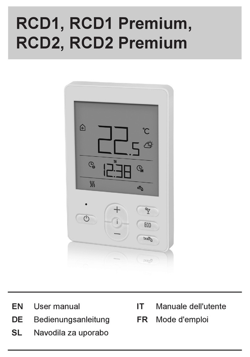
Seltron RCD1 Premium User manual

RCD
Room unit
ENEN


| 3
EN
CONTENTS
Room unit RCD1 appearance ................................................................................................................... 4
Room unit RCD2 appearance ...................................................................................................................5
Room unit display..........................................................................................................................................6
Descriptions of symbols on screen ..................................................................................................6
Info - overview of information..................................................................................................................9
Operation mode selection (RCD2 only) .............................................................................................10
Setting the requested day and night temp., and requested domestic hot water
temp............................................................................................................................................................10
Setting the temp. for frost protection............................................................................................ 11
Party function (RCD2 only) ................................................................................................................ 11
Holiday function (RCD2 only)........................................................................................................... 12
Eco function (RCD2 only) .................................................................................................................. 12
Operation mode selection (RCD2 only) ....................................................................................... 12
One-time domestic hot water warming function (RCD2 only)........................................... 13
Fireplace function (RCD2 only) ....................................................................................................... 13
Additional and service settings..............................................................................................................14
Locking settings and buttons ................................................................................................................. 21
Factory settings - reset............................................................................................................................ 22
Error description......................................................................................................................................... 22
Installation and initial operation ........................................................................................................... 23
Technical data..............................................................................................................................................24
Disposal of old electrical and electronic equipment .................................................................... 25
Mounting and electrical connection.................................................................................................... 26

4 | Instructions for use
EN
5
4
3
1
2
Illuminated display.
1
Button for increasing a setting or moving forwards.
2
Light sensor.
3
Button for reviewing data and entering settings.
4
Button for reducing the setting or moving backwards.
5
ROOM UNIT RCD1 APPEARANCE

| 5Instructions for use
EN
6
5
7
8
9
4
1
3
2
ROOM UNIT RCD2 APPEARANCE
Illuminated display.
1
Button for increasing a setting or moving forwards.
2
Light sensor.
3
Button for reviewing data and entering settings.
4
Button for turning on/o room heating.
5
Button for reducing the setting or moving backwards.
6
Button for turning on/o the Party function.
Button for turning on/o the Eco function.
Button for turning on/o the function for single heating of domestic hot
water and for turning on/o heating of domestic hot water.
7
8
9

6 | Instructions for use
EN ROOM UNIT DISPLAY
DESCRIPTIONS OF SYMBOLS ON SCREEN
Event display symbols
Operating mode display
Display of measured and requested
temp. and other information
Display of time, day of the week
and state of time programmes
Symbol Description
Warning.
When an error occurs on the heating controller, the room unit
makes two long beeps, and the symbol starts flashing. When the
error is no longer present, the symbol is lighted. When we read
the error in the error list on the controller, the symbol turns o.
Heating controller safety function turning on notification.
When a protective function occurs on the controller, the room
unit makes a single long beep, and the symbol starts flashing.
When the protective function is no longer present, the symbol is
lighted. When we read the protective function in the notification
list on the controller, the symbol turns o.
Notification about the heat accumulator.
When accumulator temp. does not meet heating needs, the room
unit makes two short beeps, and the symbol starts flashing. When
accumulator temp. falls below minimum temp., the room unit
makes three short beeps, and the symbol lights up.
Log or wood chip boiler notification.
When boiler temp.e does not meet heating needs, the room unit
makes two short beeps, and the symbol starts flashing. When
boiler temp. falls below minimum temp., the room unit makes
three short beeps, and the symbol lights up.
Pellet storage room notification.
When the pellet storage room is nearly empty or empty, the room
unit makes three short beeps, and the symbol starts flashing.
Locked buttons.
EVENT DISPLAY SYMBOLS

| 7Instructions for use
EN
ROOM UNIT DISPLAY
Symbol Description
and Measured room temp.
and Measured external temp.
and Measured domestic hot water temp.
Measured relative air humidity in the room.
and Requested day temp.
and Requested night temp.
and Requested domestic hot water temp.
and Requested temp. for frost protection.
Weather forecast - sunny.
Weather forecast - overcast.
Weather forecast - cloudy.
Weather forecast - rainfall.
Sound signalling of warnings and notifications is repeated at 20:00 if warnings
or notifications are still present. Parameters P1.8 and P1.9 define which events
should be displayed visually and by sound.
SYMBOLS FOR DISPLAYING MEASURED AND REQUESTED TEMP. AND OTHER
INFORMATION
Symbol Description
Manual intervention in controller operation.
Menu for data and settings.
Manual switch-o of liquid fuel boiler.
Room unit address (1-first or 2-second).

8 | Instructions for use
EN ROOM UNIT DISPLAY
Symbol Description
MO - Monday,
TU - Tuesday,
WE - Wednesday,
TH - Thursday,
FR - Friday,
SA - Saturday,
SU - Sunday.
Operation according to program interval - day temp. *
Operation according to program interval - night temp. *
D.h.w. warming according to program interval - switch-on interval.
D.h.w. warming according to program interval - switch-o interval.
Time when function Party or Eco is finished.
The date when the Holiday function ends.
SYMBOLS FOR DISPLAYING DAY OF THE WEEK AND STATE OF TIME PROGRAMMES
SYMBOLS FOR OPERATION MODE INDICATION
* The number by the symbol marks the first or the second time program accordingly.
Symbol Description
Room heating.
Room cooling.
Uninterrupted room heating to the requested day temperature.
Uninterrupted room heating to the requested night temperature.
Uninterrupted room cooling to the requested day temperature.
Uninterrupted room cooling to the requested night temperature.
Automatic heating shut-down - summer heating mode.
Party function active.
Eco function active.
Vacation function active.
D.h.w. warming.

| 9Instructions for use
EN
ROOM UNIT DISPLAY
Symbol Description
Permanent switch-on of d.h.w. warming.
One-time d.h.w. warming active.
Anti-legionella protection active.
Room heating switch-o. Frost protection activated.
INFO - OVERVIEW
OF INFORMATION
The room unit measures and displays the room temperature in addition to other infor-
mation about the microclimate in the room. Use the button to browse through data.
How much and which information can we browse is determined with
parameters P1.10 to P1.17. With parameter P1.18, we can set that the basic
display automatically displays the requested number of other information
that we selected for viewing information next to the measured room temp.
Information is switched on 3-second intervals.

10 | Instructions for use
EN OPERATION MODE SELECTION
(RCD2 ONLY)
By pressing the button for 2 seconds we turn room heating on or o.
By pressing the button for 2 seconds we turn domestic hot water warming on or
o.
By pressing the button for 20 seconds we switch between heating and cooling of
rooms.
Symbols for operation mode indication
- room heating
- room cooling
- d. h. w. warming
- heating or cooling of rooms o
SETTING THE REQUESTED DAY AND NIGHT TEMP.,
AND REQUESTED DOMESTIC HOT WATER TEMP.
By pressing the button or activate settings of the requested temperatures. Actual
requested temp. is displayed.
Buttons and change the requested temp. Change the setting while the value is
flashing. For setting other requested temperatures move by pressing the button .
We can set the requested day and night temp., and requested domestic hot water
temp. The icon next to the temp. shows which requested temp. we are setting.
With the next press of the button return to the basic display.
Temp. symbol
- day temperature.
- night temperature.
- d. h. w. temperature.
Setting the requested day and night temp., and the domestic hot water temp.
is enabled only when heating is on and functions Party, Eco or Vacation are not
active.

| 11Instructions for use
EN
OPERATION MODE SELECTION
(RCD2 ONLY)
SETTING THE TEMP. FOR FROST PROTECTION
PARTY FUNCTION (RCD2 ONLY)
We can change the setting of the requested room temp. which is considered when the
heating is on. When the heating is o, by pressing the button or recall the display
of the set temp.
If the button or is pressed and held for at least 2 seconds,
the setting value will begin to flash. Now you can change it with buttons and .
By pressing the button we confirm the setting.
By the next press of the button return to the basic display.
For the frost protection to be active, the boiler or the heat generator must be
turned on! Frost protection temp. setting is enabled only when heating is o
and functions Party, Eco and Vacation are not active.
Party function enables to turn on heating according to the requested comfort tempera-
ture at any time. Function can be activated by pressing the button .
Now we can change the requested comfort temperature with buttons and .
Change the setting while the value is flashing. By pressing the or button, we move
to time setting. Use buttons and to set time until when comfort heating should
operate. Change the setting while the value is flashing. By the next press of the button
or return to the basic display.
When the Party function is on, we can check or change settings by pressing button
or .
Party function can be reactivated before expiration of time by pressing again the but-
ton (RCD2 only).
Requested comfort or Party temp.
Time when Party function expires
Party function display

12 | Instructions for use
EN OPERATION MODE SELECTION
(RCD2 ONLY)
ECO FUNCTION (RCD2 ONLY)
Eco function enables activation of heating according to the requested saving temp. at
any time. Function can be activated by pressing the ECO.
Now we can change the requested saving temp. with buttons and .
Change the setting while the value is flashing. By pressing the ECO or button, we
move to time setting. Buttons and are used to set time until when saving heating
should operate. Change the setting while the value is flashing. By the next press of the
ECO or button, return to the basic display. When Eco function is on, we can check
or change settings by pressing button or . Eco function can be turned o before
expiration of time by pressing ECO button again.
Requested saving or Eco temp.
Time when Eco function expires
Eco function display
Vacation function enables activation of heating according to the requested saving
temp. until a specific date at any time. Function can be activated by pressing the ECO
button for 10 seconds.
requested saving or Holiday temp.
date when Holiday function expires
Vacation function display
Now we can change the requested saving temperature with buttons and . Change
the setting while the value is flashing. By pressing the ECO or button, we move to date
setting. Use buttons and to set date until when vacation heating should operate.
Change the setting while the value is flashing. By the next press of the ECO or button,
return to the basic display. When Holiday function is on, we can check or change set-
tings by pressing button or . Vacation function can be turned o before expiration
of time by pressing again the ECO button for 10 seconds
HOLIDAY FUNCTION (RCD2 ONLY)

| 13Instructions for use
EN
OPERATION MODE SELECTION
(RCD2 ONLY)
ONE-TIME DOMESTIC HOT WATER WARMING
FUNCTION (RCD2 ONLY)
FIREPLACE FUNCTION (RCD2 ONLY)
Function enables that we can turn one-time d.h.w. heating to the requested temp. at
any time. The function is automatically turned o when domestic hot water is warm or
after one hour. Function can be activated by pressing the button .
Now we can change the requested temp. of domestic hot water by pressing button
and . Change the setting while the value is flashing. By pressing the button again,
return to the basic display. One-time domestic hot water function can be turned o
before expiration by pressing .
Requested d. h. w. temp.
One-time d. h. w. warming function display
The Fireplace function enables temporary shut-down of room temp. eect on room
heating regulation. This function is turned on when we make a fire in the fireplace in
the living room which has the room unit. This prevents to reduce the temp. levels in
other rooms due to increase of temp. in the living room.
Function can be activated by pressing the button for 10 seconds.
Operation of fireplace function is indicated by the flashing symbol .
Fireplace function works at least for the amount of time set with parameter S1.13. After
expiration of time, it works until the measured room temp. is higher than the requested
room temp. that is set.
Fireplace function can be turned o before expiration of time by pressing again the
button for 10 seconds.
By pressing , any setting can be terminated at any time, and we can return to
the basic display.

14 | Instructions for use
EN ADDITIONAL AND
SERVICE SETTINGS
Menu symbol
Information or parameter value dis-
play for setting
Group name display and consecutive
parameter number
Access to additional settings is enabled through the menu.
Data and parameters are located in five groups in the menu:
t1 - measured and requested temperatures,
d1 - data on room unit and heating controller,
P1 - user settings (parameters),
P2 - user settings (parameters)
S1 - service settings (parameters).
By pressing the button for 2 seconds, we enter the menu.
Move between groups with buttons and .
By pressing the button , we enter the selected group.
Move between information and parameters for settings in individual groups with but-
tons and . Only parameters in groups P1, P2, and S1 can be changed.
By pressing , the setting value starts flashing. Now we can change the parameter
value with button and . Confirm the set value by pressing the button .
By pressing button or by pressing the button for 2 seconds, we move one
level back in any level of settings.
...

| 15Instructions for use
EN
ADDITIONAL AND
SERVICE SETTINGS
INFORMATION GROUP T1 - TEMPERATURES
No. Description
t1.1 T1 CONTROLLER SENSOR
Measured and calculated temp. for T1 sensor are displayed alternately.
t1.2 T2 CONTROLLER SENSOR
Measured and calculated temp. for T2 sensor are displayed alternately.
t1.3 T3 CONTROLLER SENSOR
Measured and calculated temp. for T3 sensor are displayed alternately.
t1.4 T4 CONTROLLER SENSOR
Measured and calculated temp. for T4 sensor are displayed alternately.
t1.5 T5 CONTROLLER SENSOR
Measured and calculated temp. for T5 sensor are displayed alternately.
t1.6 T6 CONTROLLER SENSOR
Measured and calculated temp. for T6 sensor are displayed alternately.
t1.7 T7 CONTROLLER SENSOR
Measured and calculated temp. for T7 sensor are displayed alternately.
t1.8 T8 CONTROLLER SENSOR
Measured and calculated temp. for T8 sensor are displayed alternately.
t1.9 T9 CONTROLLER SENSOR
Measured and calculated temp. for T9 sensor are displayed alternately.
t1.10 T10 CONTROLLER SENSOR
Measured and calculated temp. for T10 sensor are displayed alternately.
t1.11 T11 CONTROLLER SENSOR
Measured and calculated temp. for T11 sensor are displayed alternately.
t1.12 T12 CONTROLLER SENSOR
Measured and calculated temp. for T12 sensor are displayed alternately.
t1.13
THE FIRST HEATING CIRCUIT TR1
Measured and requested room temp. of the first heating circuit are displayed
alternately.
t1.14
THE SECOND HEATING CIRCUIT TR2
Measured and requested room temp. of the second heating circuit are dis-
played alternately.
t1.15 DIRECT CIRCUIT
Calculated temp. of the riser for direct circuit is displayed.

16 | Instructions for use
EN ADDITIONAL AND
SERVICE SETTINGS
INFORMATION GROUP D1 - GENERAL INFORMATION
PARAMETER GROUP P1 - BASIC PARAMETERS
No. Description Range
P1.1 TEMPERATURE DISPLAY ROUND-OFF
With this setting, we can determine to what value the meas-
ured Temp. display will be rounded o.
0 - 0.1 °C
1 - 0.2 °C
2 - 0.5 °C
3 - 1.0 °C
P1.2 AUTOMATIC EXIT TIME
This setting determines the time after which the display returns
to basic mode.
3 ÷ 180 s
(15)
P1.3 DISPLAY ILLUMINATION SHUT-OFF TIME
This setting determines the time after which display lighting is
reduced or shut o.
10 ÷ 180 s
(30)
P1.4 DISPLAY ILLUMINATION OPERATION MODE
This setting determines type of operation of display illumina-
tion.
The following settings are available: 0 - no display illumination.
1- The display has maximum brightness when entering settings
to the room unit. After a delay, display illumination is reduced
to the minimum value.
2- Same as 1, but display illumination is adapted to the amount
of light in the room.
3- Same as 2, but room unit display is completely turned o
in standby mode during night Temp. interval if this occurs
between 6pm and 6am.
0 ÷ 3 (2)
No. Description
d1.1 ROOM UNIT TYPE (RCD1, RCD2 etc.)
d1.2 ROOM UNIT SOFTWARE VERSION
d1.3
TYPE OF CONTROLLER CONNECTED TO ROOM UNIT
WXD10B = 20 WXD10 = 21
WXD20 = 22 WDC10b = 32
WDC10 = 33 WDC20 = 42
KXD10B = 50 KXD10 = 51
KXD20 = 52 KPD10 = 71
KUD10 = 81 CMP25 = 92
d1.4 Software version of the controller
d1.5 Hydraulic scheme of the controller
d1.6 LIGHT SENSOR
Measured light of the room where the room unit is installed is displayed.

| 17Instructions for use
EN
ADDITIONAL AND
SERVICE SETTINGS
No. Description Range
P1.5 MINIMUM SCREEN ILLUMINATION
This setting determines minimum display illumina-
tion.
0 ÷ 100 % (5)
P1.6 MAXIMUM SCREEN ILLUMINATION
This setting determines maximum display illumina-
tion.
0 ÷ 100 % (80)
P1.7 DISPLAY CONTRAST
This setting determines display contrast.
1 ÷ 8 (6)
P1.8 SOUND
This setting determines when sound is activated
0 - never
1 - buttons
2 - buttons and warnings
3 - buttons, warnings,
and notifications
P1.9 DISPLAYING WARNINGS AND MESSAGES
This setting determines whether warnings and notifi-
cations are displayed.
0 - no display
1 - warnings
2 - warnings and
notifications
P1.10 BASIC DISPLAY
This setting determines which information will be
displayed on the basic display.
1 - room temp.
2 - auxilliary temp.
3 - d. h. w. temp.
4 - humidity
5 - air pressure
6 - auxiliary sensor
7 - air quality*
11 - T1 controller sensor
...
22 - T12 controller sen-
sor
P1.11 FIRST DISPLAY IN THE INFO LINE
This setting determines which information will be
displayed first in the info line.
0 - no display
1 - room temp.
2 - auxilliary temp.
3 - d. h. w. temp.
4 - humidity
5 - air pressure
6 - auxiliary sensor
(AUX) 7 - air quality*
11 - T1 controller sensor
...
22 - T12 controller sen-
sor

18 | Instructions for use
EN
No. Description Range
P1.12 SECOND DISPLAY IN THE INFO LINE
This setting determines which information will be
displayed second in the info line.
Setting range is identical
to parameter P1.11.
Factory setting is:
3 - d. h. w. Temp.
P1.13 THIRD DISPLAY IN THE INFO LINE
This setting determines which information will be
displayed third in the info line..
Setting range is identical
to parameter P1.11.
Factory setting is:
4 - humidity
P1.14 FOURTH DISPLAY IN THE INFO LINE
This setting determines which information will be
displayed fourth in the info line.
Setting range is identical
to parameter P1.11.
Factory setting is:
5 - air pressure
P1.15 FIFTH DISPLAY IN THE INFO LINE
This setting determines which information will be
displayed fifth in the info line.
Setting range is identical
to parameter P1.11.
Factory setting is:
0 - no display
P1.16 SIXTH DISPLAY IN THE INFO LINE
This setting determines which information will be
displayed sixth in the info line.
Setting range is identical
to parameter P1.11.
Factory setting is:
0 - no display
P1.17 SEVENTH DISPLAY IN THE INFO LINE
This setting determines which information will be
displayed seventh in the info line.
Setting range is identical
to parameter P1.11.
Factory setting is:
0 - no display
P1.18 NUMBER OF INFORMATION ON BASIC DISPLAY
This setting determines how many information from
the info line should be alternatively displayed on the
basic display.
1 ÷ 9 (1)
PARAMETER GROUP P2 - ROOM UNIT ADDRESS
No. Description Range
P2.1 ROOM UNIT ADDRESS
This setting determines room unit address. It can be 1
or 2. During initial operation, room unit address is set
automatically.
0 - auto setting
1 - address 1
2 - address 2
* RCD1 Premium and RCD2 Premium only.
ADDITIONAL AND
SERVICE SETTINGS

| 19Instructions for use
EN
S1 PARAMETER GROUP - SERVICE PARAMETERS
ADDITIONAL AND
SERVICE SETTINGS
No. Description Range
S1.2
ROOM TEMPERATURE
This setting determines which sensor is used for room
temp.
Info: For setting 3, median value of the installed and
auxiliary sensor is calculated for room temp.
0 - none
1 - built-in sensor
2 - auxiliary sensor
(AUX)
3 - built-in and addi-
tional sensor
S1.3
CALIBRATION OF BUILT-IN TEMPERATURE SENSOR
This setting determines the correction of measured
temp. of the built-in sensor.
-5,0 ÷ 5,0 °C (0,0)
S1.4
AUXILIARY TEMP. SENSOR (AUX) CALIBRATION
This setting determines the correction of measured
temp. of the auxiliary sensor.
-5,0 ÷ 5,0 °C (0,0)
S1.5
RELATIVE HUMIDITY SENSOR CALIBRATION
This setting determines the correction of measured
relative humidity in the room.
-10 ÷ 10 % (0)
S1.6
AIR PRESSURE SENSOR CALIBRATION
This setting determines correction of measured air
pressure.
-100 ÷ 100 mb (0)
S1.7
AIR QUALITY SENSOR CALIBRATION
This setting determines the correction of measured air
quality.
-1000 ÷ 1000 (0)
S1.8
LIGHT SENSOR CALIBRATION
This setting determines the correction of measured
lighting in the room.
0,5÷ 2 (1)
S1.9
LOCKING THE MENU
This setting limits access to parameter groups in the
menu.
0 - no lock
1 - S1
2 - P1, P2 and S1
S1.10
LOCKING BUTTONS
This setting locks button functionality.
Operation of locking buttons function is described in
the chapter »Locking butons«.
0 - no lock
1 - operation type,
2 - same as 1 and
functions,
3 - same as 2 and desi-
red temp.,
4 - same as 3 and info
browsing and settings.
S1.11
MINIMUM SETTING OF REQUESTED TEMP.
This setting determines minimum possible setting of
room temp.
4 ÷ 40 °C (6)

20 | Instructions for use
EN ADDITIONAL AND
SERVICE SETTINGS
No. Description Range
S1.12
MAXIMUM SETTING OF REQUESTED TEMP.
This setting determines maximum possible setting of
room temp.
4 ÷ 40 °C (30)
S1.13
TIME OF IGNORING ROOM TEMP. (RCD2 only)
Used with the »fireplace« function. Operation of fire-
place function is described in the chapter »Fireplace
Function«
1 ÷ 12 ur (5)
S1.14
ALTITUTE FOR WEATHER FORECAST
This setting enters the altitude of the room unit. This
improves precision of weather forecast.
0 ÷ 1999 m (300)
Other manuals for RCD1 Premium
1
This manual suits for next models
3
Table of contents
Other Seltron Thermostat manuals

Seltron
Seltron T1 User manual

Seltron
Seltron RCD1 Premium User manual

Seltron
Seltron ST User manual

Seltron
Seltron RT Series User manual

Seltron
Seltron ST User manual

Seltron
Seltron RCD3 Setup guide
Seltron
Seltron RCD20 User manual

Seltron
Seltron DD2+ User manual
Seltron
Seltron RCD20 How to use
Seltron
Seltron ST2 User manual