Seltron T1 User manual

Room thermostat T1
Raumthermostat T1
Thermostat d'ambiance T1
Thermostato ambiente
T1
Chronotermostato de ambiente T1
Mode d’emploi
Anleitungen
D
GB
Instructions
I
struzioni
I
F
E
Manual

D Bedienungsanleitungen...................................23
Betriebsanleitungen ........................................32
Montageanleitungen .......................................36
Technische Daten, Stellungsnahme................39
F Mode d'emploi................................................61
Réglage...........................................................70
Montage..........................................................74
Les données techniques, les declarations .......77
Istruzioni per l’uso..........................................42
Istruzioni per l’impostazione ..........................51
Istruzioni per il collegamento.........................55
Dati tecnici, dichiarazioni...............................58
I
User manual....................................................4
Setting manual................................................13
Installation manual..........................................17
Technical data, statements..............................20
GB
E Manual de usuario...........................................80
Manual de ajustes ...........................................90
Manual de instalación.....................................94
Datos técnicos, declaraciónes ........................97
DF I GBE

USER MANUAL
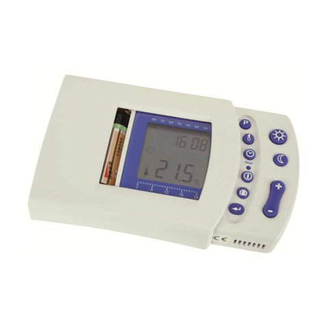
T1 is a powerful, modern designed room thermostat with weekly
program timer. On T1 is possible to set four temperature levels,
which ensures maximal comfort and energy saving. T1 is simple to
use and very practical with help of the Party and Eco keys. Every
key press or command activation is signalised with a beep sound.
Room thermostat T1 also enables remote activation and selection
between heating / cooling mode.
LEGEND
Hold key while pressing other keys.
Hold key until you hear a beep sound.
Press and release key.
Press key to increase or decrease value.
4
Appearance and description of T1
GB

Operating mode
USER MANUAL 5
Controlled object
- boiler
- actuator
- pump
Day and time
Knob for day
temperature
setting
Picture 1
PARTY -
day
tempera-
ture mode
Stand-by Night
temperature
setting
Operation
according to
the
program
timer
Relay output
ON - active
OFF - inactive
Program timer
- day temperature
- night temperature
ECO - saving
temperature mode
- stand-by
- heating
- cooling
PARTY
ECO
Temperature
display
GB

USER MANUAL
Operating mode selection
Operation
Press key (Picture 2). On the
display appears symbol , when
heating or symbol when cooling.
Thermostat operates according to
the program timer.
Stand-by
Press key (Picture 3). On the
display appears symbol .
Frost protection remains active.
Picture 2
6
Day temperature
Turn knob to set the desired
day temperature between 10 °C
and 30 °C (Picture 4).
Setting the day and night temperature
Picture 4
Picture 3
Night temperature
Hold key ( ) for approx. 5 seconds (Picture 5). Release key
after you hear a beep. Now press key ( ) or ( ) to set the
desired night temperature (Picture 6). To save and quit set-up,
press key ( ) once again .
GB

USER MANUAL 7
Picture 6
Picture 5
PARTY and ECO operating mode
PARTY - day temperature operation
Press key . Use key ( ) or ( ) to set duration of the
PARTY mode between 1 and 24 hours. For permanent PARTY
mode, select on.
To stop PARTY mode at anytime, press key .
ECO - night temperature operation
Press key . Use key ( ) or ( ) to set duration of the
ECO mode between 1 and 24 hours. For permanent ECO mode,
select on.
To stop ECO mode at anytime, press key .
Hold key for approximately 15 seconds. Release the key after
you hear a beep sound. Use key ( ) or ( ) to set duration
of the HOLIDAY mode between 1 and 99 days.
To stop HOLIDAY mode at anytime, again hold the key for 15
seconds.
Holiday mode
The ECO temperature reduction is setted in program group P1.2 (page 15).
i
GB

Day
Hold both keys and , then
press key ( ) or ( ) to set
the day (Picture 9). The days are
marked from 1 to 7. Monday is
marked as 1and Sunday as 7.
i If the battery exchange isn't completed within 20 s, the time is set to
Monday, 20:00.
Picture 9
Setting the accurate time
Hours
Hold key and press key ( )
or ( ) to set the hours (Picture
7).
Minutes
Hold key and press key
( ) or ( ) to set the
minutes (Picture 8).
Picture 8
Picture 7
USER MANUAL
8
The HOLIDAY mode temperature is setted in program group P1.4 (page 15).
Factory default HOLIDAY temperature is 12 °C.
i
GB

USER MANUAL 9
Pre-setted time programs
Program selection
Hold key and by pressing key select the suitable time
program (Picture 10). Select between Pr1, Pr2, Pr3, Pr4 and- - -.
The selected time program always overwrites the previous one. To
keep the current time program active, select - - -.
Table of pre-setted time programs
Picture 10
Day TimeDay Time
Day TimeDay Time
GB

Time
command
USER MANUAL
Modifying the time program
10
The selected time program can be modified. In that way you can
make your own time program.
Hold key and press key (Picture 11). Release both keys
after you hear a beep. The display shows CH1 (Picture 12).
Picture 11 Picture 12
Press key ( ) or ( ) to select the program space that you
want to modify. The display simultaneously shows the time
command and the successive number of the program space
(Picture 13).
Picture 13
Successive number of the
program space
Program timer
- night temperature
- day temperature
GB

Now press key ( ). On the display starts to flash day. Press
key ( ) or ( ) to set day, then press key ( ). On the
display starts to flash hours. Press key ( ) or ( ) to set
hours, then press key ( ). On the display starts to flash
minutes. Press key ( ) or ( ) to set minutes, then press key
( ). The display stops flashing. Now is possible to move to
the next program space. Press ( ) to move to the next program
space or press ( ) to move to the previous program space.
The time program has 32 program spaces. Time commands for day
and night temperature are successively followed. Unused time
programs are marked as --:-- (Picture 14).
USER MANUAL 11
Picture 14
Selection between heating or cooling
To switchover between heating and cooling and vice versa, hold
key for approximately 10 seconds (Picture 15). Release key
after you hear a beep. The display writes out active mode for a
few seconds, HEA - heating or COO - cooling (Picture 16).
Unused time
command
Picture 15 Picture 16
GB

USER MANUAL
12
Battery exchange
Command to quick save and quit (Escape)
Every time you wish to quick store and quit set-up, hold key and
press key . Release both keys after you hear a beep.
Remote control
The day temperature mode can be remotely activated with a tele-
phone device.
For analogue telephone line is available device G1-D. Device G44
is intended for remote control with GSM mobile telephone.
i All modifications you made, are stored.
Empty batteries are indicated with the low
contrast display. We suggest the battery
replacement every 2 years. T1 is supplied
with two alkaline batteries 1.5 V type
AAA. Battery socket is inside the T1.
To remove thermostat from the wall plate,
do the following. Hold thermostat in height
of keys and pull it towards yourself
(Picture 17 - OPEN). After battery ex-
change, put T1 back on the wall plate, by
doing the following. Hook T1 on top and
push it with bottom towards the wall plate
(Picture 17 - CLOSE).
Battery exchange should be done within 20 seconds. In other case you
will have to set the accurate time again.
Picture 17
GB
i

SETTING MANUAL 13
Menu
The menu has four groups. Group CH1 represents the time
program, group d1 the thermostat’s data, group P1 the
thermostat’s program settings and group S1 the thermostat’s
service settings.
Menu
To enter menu hold key and press key (Picture 18).
Release keys after you hear a beep. The display shows the first
group CH1.
Menu navigation
In menu have keys new meaning, marked bellow them (Picture
19). To move between the groups press key ( ) to move to
the left and key ( ) to move to the right (Picture 20). To move
within the group press key ( ), to move down between the
lines and key ( ) to move up between the lines. For your
better understanding are all the lines marked. First two symbols
mark the group and the third symbol successive number of the
line in group (Picture 21).
Picture 18
Move to the
left
Move to
the right
Move up or
increase
Picture 19
Move down or
decrease
GB

Group S1 is by default (factory) settings locked.
For unlocking the group S1 see chapter Service group S1.
SETTING MANUAL
14
Picture 20
Picture 21
Successive Nr.
of the line
Group
name Parameter
Time program CH1
For changing the time program see chapter Modifying the time
program (page 10).
Data group d1
This group is sort of T1 identification. Group d1 only shows data
about T1, meanwhile changing isn’t possible. Group d1 contains
the following data:
- [d1.1] thermostat type (T1)
- [d1.2] software version
- [d1.3] heating or cooling
- [d1.4] ED constant and regulated object
- [d1.5] temperature sensor calibration
- [d1.6] reserved
Entrance
GB

SETTING MANUAL 15
Program group P1
Program group P1 is used for the thermostat user settings. To
change the selected parameter, hold key for approximately 5
seconds. Parameter starts to flash. Press key ( ) or ( ) to
set the parameter value. To store the setted value, again hold
key for approximately 5 seconds. Group P1 contains the
following parameters; (default setting):
- [P1.1] night temperature (6 °C ÷ 26 °C); (17 °C )
- [P1.2] temperature reduction in ECO mode(0 °C ÷ -9 °C); (-3 °C)
- [P1.3] frost protection temperature (0 °C ÷ 20 °C); (6 °C)
- [P1.4] holiday mode temperature (5 °C ÷ 25 °C); (12 °C)
- [P1.5] ED constant (10 min ÷ 50 min); (20 min)
- [P1.6] display of controlled device (- - - none, 1- boiler,
2- pump, 3- mixing valve); (1)
- [P1.7] temperature sensor calibration (-2 °C ÷ 2 °C); (0 °C)
Service group S1
Service group S1 is used for the thermostat service settings. To
change the selected parameter, hold key for approximately 5
seconds. Parameter starts to flash. Press key ( ) or ( )
to set the parameter value. To store the setted value, again hold
key for approximately 5 seconds. Group S1 contains the
following parameters; (default setting):
- [S1.1] group locking
(- - - unlocked, 1- locked S1, 2- locked S1 and P1); (1)
- [S1.2] measured temperature round up
(0.1 °C, 0.2 °C, 0.5 °C, 1.0 °C); (0.5 °C)
GB

i Access to parameter S1.1 is possible in the following way. Hold key for
20 seconds (picture 22). Release the key after you hear a beep sound. On the
display appears parameter (S1.1). Now it is possible to modify this and other
parameters.
SETTING MANUAL
16
To restore the factory settings
hold keys and for approx.
20 seconds (Picture 23). Release
keys after you hear a beep.
Picture 23
Factory settings
Picture 22
GB

INSTALLATION MANUAL 17
Place of mount
Place of mount is very important for proper T1 operation. Suitable
places are inner walls, which aren’t exposed to sun light and other
sources of heat or wind. T1 should be mounted approximately 150
cm above the floor (Picture 24).
Mounting the wall plate
Remove the T1 from the wall
plate, by doing the
following. With one hand
hold T1 in height of keys and
with other hand the wall pla-
te. Now pull them apart
(Picture 25).
Picture 24
Picture 25
GB

WARNING: Mounting and wiring connections must be done by a
qualified installer or authorized company. Local regulations or VDE
0100 and EN IEC 60364 regulations for electrical installations must
be considered by doing the wiring connections.
Bring the wires through the opening in bottom of the wall plate
(Picture 27- position A). Connect wires into the terminals 1, 2 and
3. Room thermostat is capable to control the circulation pump
(Picture 28a), actuator (Picture 28b), burner (Picture 28c) or fan
(Picture 28d).
INSTALLATION MANUAL
Unscrew and temporarily remove the protection cover (Picture 26).
Room thermostat is intended for wall mounting. In case you don’t
have installed a flush box, tear away the drilling template from the
package and mark drilling holes. Use enclosed screws to fasten the
wall plate on the wall (Picture 27). After you have done connecting
the wires (see chapter Connecting the wires), screw back the
protection cover. Now put T1 back onto the base by doing the
following. Hook T1 on top of the wall plate and push it with bottom
towards the wall plate (Picture 17- CLOSE).
Picture 26 Picture 27
Connecting the wires
18
WallFlush box
GB

INSTALLATION MANUAL 19
Picture 28a Picture 28b
Picture 28d
Picture 28c
Connecting the Telewarm
Connect Telewarm G1-D or
Telewarm G44 into the free
terminals on the wall plate
(Picture 29).
To learn more about connecting
the Telewarm on electric and
telephone network see User
manual for Telewarm.
Picture 29
Make sure you have disconnected the main power switch, before you interfere in
the wiring.
GB

Model: ............................................T1
Operation method:..........................P–controller (ON / OFF)
Power supply:.................................2 batteries LR03, type AAA
Relay output:..................................230 V ~ / 6 (2) A
Consumption:................................. I= 0,022 mA; P= 0,066 mW
Temperature sensor:......................Murata NTC (10 kE)
Safety class:...................................IP 30 by SIST EN 60529
Degree of protection:...................... II by EN 60730-1
Housing:.........................................ABS thermoplastic, white
Dimensions (l × w × h):...................72 × 32 × 112 [mm]
Weight:........................................... 150 g
Technical data
Seltron d.o.o. declares, with full responsibility, that room thermo-
stat T1 meets the requirements and rules for the electrical equip-
ment, designed to use within certain voltage levels (EC directive
for low voltage (LVD) 73/23 EEC, 93/68 EEC) and requirements
and rules for electro-magnetic compatibility (EMC) (EC directive
for electro-magnetic compatibility 89/336 EEC, 92/31 EEC, 93/68
EEC).
Product description:
Room thermostat T1
Applied standards:
EN 60730-1:1995, EN60730-2-9:1997,
EN 50081-1:1995, EN 50082-1:1995,
EN 55014-1:2001, EN 55014-2:1997.
Conformity with standards and directives
TECHNICAL DATA, STATEMENTS
20
GB
Table of contents
Languages:
Other Seltron Thermostat manuals
Seltron
Seltron ST2 User manual
Seltron
Seltron ST User manual
Seltron
Seltron RCD1 Premium User manual
Seltron
Seltron RCD20 User manual
Seltron
Seltron DD2+ User manual
Seltron
Seltron RCD1 Premium User manual
Seltron
Seltron RCD20 How to use
Seltron
Seltron RT Series User manual
Seltron
Seltron RT Series How to use
Seltron
Seltron RCD3 Setup guide
Popular Thermostat manuals by other brands
Nelson
Nelson TH4X325 Installation and maintenance instructions
Danfoss
Danfoss TP75-RF Installation & commissioning guide
Powrmatic
Powrmatic MC300 multi user manual

EBECO
EBECO EB-Therm 500 manual

Lux Products
Lux Products LUXPRO PSDH021Ba Installation and operating instructions

INFLOOR
INFLOOR 29050 owner's manual

