Sema Connect 7 Series User manual

Series 7 / 7 Plus EV
Charging Station
1 — Last update: 05/19/2021
Installation Manuals
Copyright ©2021 SemaConnect, Inc. All rights reserved.

Table of Contents
1. Series 7/7 Plus EV Charging Station ..................................................................................................... 1
1.1. Safety and Compliance ................................................................................................................... 2
1.2. Series 7 Electrical Requirements / Wiring Diagram.......................................................................... 4
1.3. Series 7 Plus Electrical Requirements / Wiring Diagram.................................................................. 6
1.4. Pedestal Mount ............................................................................................................................... 9
1.4.1. Parts List .............................................................................................................................. 10
1.4.2. Anchor Plate Installation ....................................................................................................... 12
1.4.3. Pedestal Installation.............................................................................................................. 14
1.4.4. Charging Station Head Installation ........................................................................................ 16
1.5. Wall Mount .................................................................................................................................... 19
1.5.1. Parts List .............................................................................................................................. 20
1.5.2. Wall Mount Installation.......................................................................................................... 22
1.5.3. Charging Station Head Installation ........................................................................................ 24
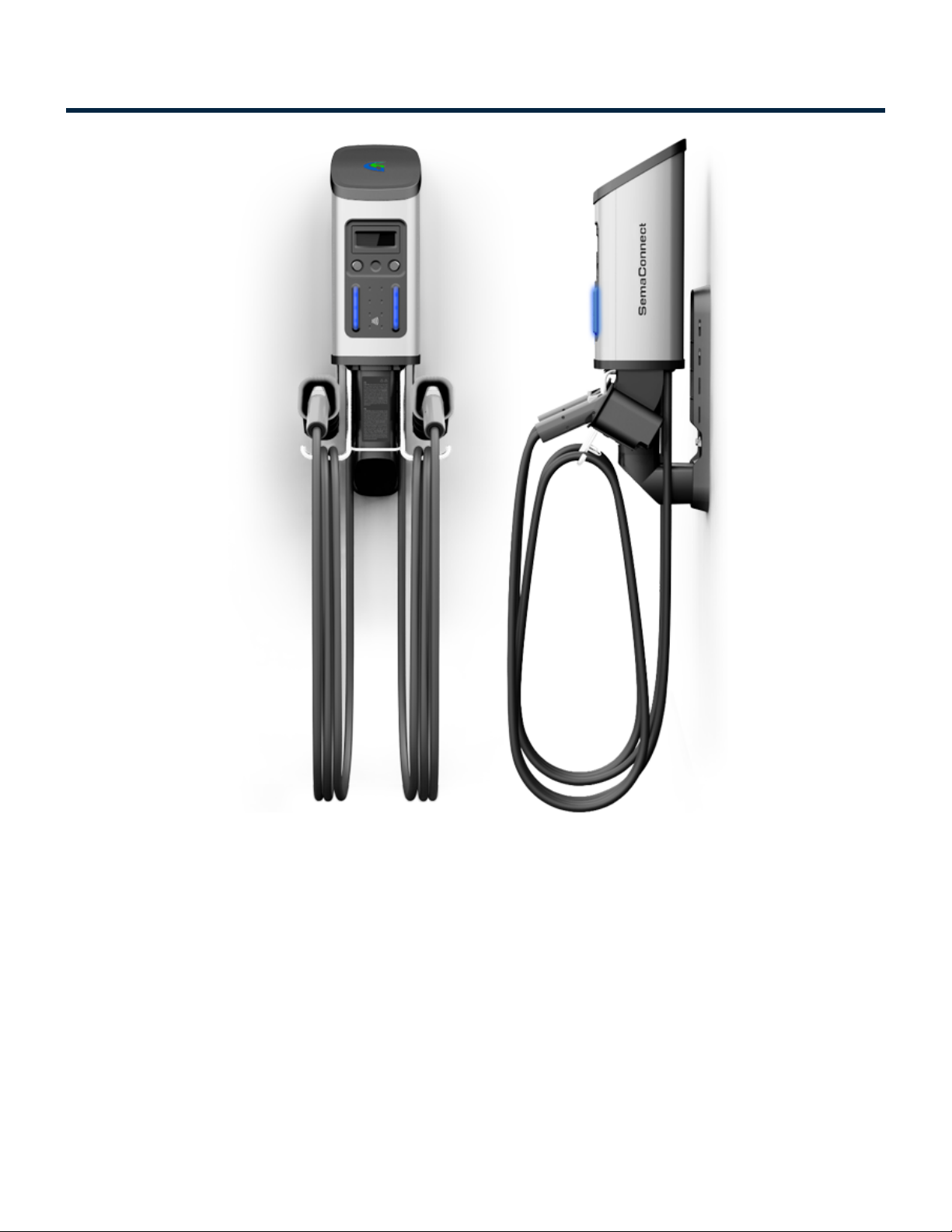
1. Series 7/7 Plus EV Charging Station
Installation Manuals Series 7 / 7 Plus EV Charging Station - 1
Copyright ©2021 SemaConnect, Inc. All rights reserved. Page 1 of 26

1.1. Safety and Compliance
This document provides instructions to install the Series 7 and Series 7 Plus Charging Stations and should
not be used for any other products. This product must be installed in accordance with the National Electrical
Code (NEC), the Canadian Electrical Code (CEC) or any applicable local code.
Review this manual and consult a licensed contractor and/or electrician before installation to ensure
compliance with local building practices, climate conditions, safety standards, and state and local codes.
The Series 7/Series 7 Plus Charging Station should be installed by a licensed contractor/ electrician and
inspected by a qualified installer prior to initial use. Under no circumstances will compliance with the
information in this manual relieve the user of responsibility to comply with all applicable codes and safety
standards.
This document describes the most common installation and mounting methods. Contact SemaConnect Inc.
where it is not possible to perform an installation using the procedures provided in this document.
SemaConnect Inc. is not responsible for damages that may occur or result from installations that are not
described in this document.
Note: Make sure to TURN OFF the breakers before doing any electrical work!
General
The Series 7/Series 7 Plus Charging Station is grounded through a dedicated conductor to the ground
connection at the power distribution panel.
This equipment has been tested and found to comply with the limits for a Class A digital device, pursuant to
Part 15 of the FCC rules. These limits are designed to provide reasonable protection against harmful
interference when the equipment is operated in a commercial environment. The equipment generates, uses,
and can radiate radio frequency energy and, if not installed and used in accordance with the instruction
manual, may cause harmful interference to radio communications. Operation of this equipment in a
residential area is likely to cause harmful interference at their own expense.
Statements
Reasonable effort has been made to ensure that the specifications and other information in this manual are
accurate and complete at the time publication. However, specifications and other information in this manual
are subject to change at any time without prior notice.
Use of the Series 7/Series 7 Plus Charging Station in a manner not intended or any modification not
approved by the manufacturer will void the limited warranty. Other than the limited product warranty
provided by SemaConnect, this manual and the SemaConnect Inc. products are provided “AS IS,” and
Installation Manuals Series 7 / 7 Plus EV Charging Station - 1
Copyright ©2021 SemaConnect, Inc. All rights reserved. Page 2 of 26

SemaConnect Inc. expressly disclaim all implied warranties, including any warranty of design,
merchantability, and fitness for a particular purposes and non-infringement, to the maximum extent
permitted by law.
IN NO EVENT SHALL SEMACONNECT INC. OR ITS AUTHORIZED DISTRIBUTORS BE LIABLE FOR ANY
INDIRECT, INCIDENTAL, SPECIAL, PUNITIVE, OR CONSEQUENTIAL DAMAGES, INCLUDING WITHOUT
LIMITATION, LOST PROFITS, LOST DATA, LOSS OF USE, COST OF COVER, OR LOSS OR DAMAGE
TO THE SERIES 7 CHARGING STATION ARISING OUT OF OR RELATING TO THE USE OR INABILITY
TO USE THIS MANUAL, OR RELATED PRODUCT, EVEN IF SEMACONNECT INC. OR ITS AUTHORIZED
DISTRIBUTORS HAVE BEEN ADVISED OF THE POSSIBILITY OF SUCH DAMAGES.
The Series 7 and Series 7 Plus is a trademark of SemaConnect, Inc. All other products or services
mentioned are the trademarks, service marks, registered trademarks, or registered service marks of their
respective owners. This material is protected by the copyright laws of the United States and other countries.
It may not be modified, reproduced, or distributed without the prior, express written consent of
SemaConnect, Inc.
Copyright ©2021 SemaConnect, Inc. All rights reserved.
Installation Manuals Series 7 / 7 Plus EV Charging Station - 1
Copyright ©2021 SemaConnect, Inc. All rights reserved. Page 3 of 26
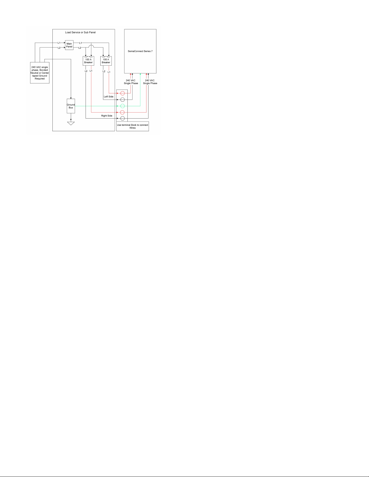
1.2. Series 7 Electrical Requirements / Wiring
Diagram
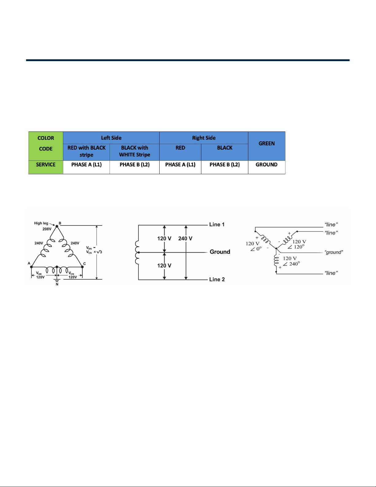
Wiring Color Code
The illustrations and diagrams in this document reflect Level-2 wiring color code. Strictly adhere to the wire
color codes to ensure proper installation.
Use 10 AWG wire minimum (ensure compliance with electrical codes).
Wiring Diagram
Connect the Series 7 Charging Stations to any one of the power sources (Figure-1):
1. 240 VAC three phase, Delta system, Center tap grounded
2. 208 VAC three phase, Wye system, Bonded neutral
3. 240 VAC single phase, Bonded neutral
In a Wye system connect the Series 7 Charging Stations to any of the two lines. Do not use the system if it
has a floating ground.
In a delta system, connect the Series 7 Charging Station only to a center-tapped grounded transformer only
as shown above. Connect the station to the side where ground is bonded (in figure 2.C, Line A and Line C).
This allows voltages to remain constant regardless of other loads that may be using the lines. Please do not
connect to other type of power sources shown below.
Installation Manuals Series 7 / 7 Plus EV Charging Station - 1
Copyright ©2021 SemaConnect, Inc. All rights reserved. Page 4 of 26
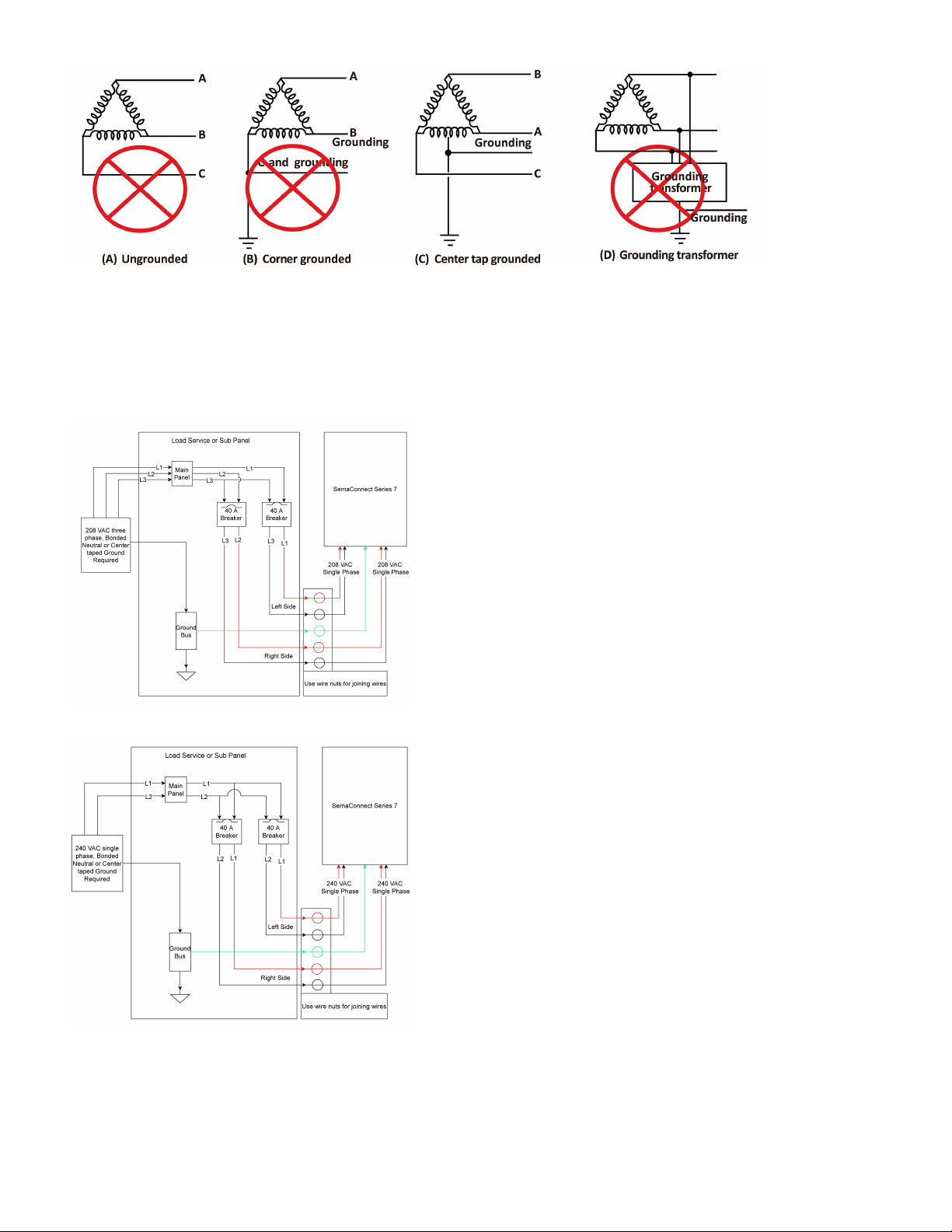
Wiring To System – Separate Power
The figure below describes the wiring for installation of Series 7 Charging Station on a separate power
circuit.
Installation Manuals Series 7 / 7 Plus EV Charging Station - 1
Copyright ©2021 SemaConnect, Inc. All rights reserved. Page 5 of 26

1.3. Series 7 Plus Electrical Requirements /
Wiring Diagram
Wiring Color Code
The illustrations and diagrams in this document reflect Level-2 wiring color code. Strictly adhere to the wire
color codes to ensure proper installation.
Use 10 AWG wire minimum (ensure compliance with electrical codes).
Wiring Diagram
Connect the Series 7+ Charging Stations to any one of the power sources (Figure-1):
1. 240 VAC three phase, Delta system, Center tap grounded
2. 208 VAC three phase, Wye system, Bonded neutral
3. 240 VAC single phase, Bonded neutral
In a Wye system connect the Series 7 Plus Charging Stations to any of the two lines. Do not use the system
if it has a floating ground.
In a delta system, connect the Series 7 Plus Charging Station only to a center-tapped grounded transformer
only as shown above. Connect the station to the side where ground is bonded (in figure 2.C, Line A and
Line C). This allows voltages to remain constant regardless of other loads that may be using the lines.
Please do not connect to other type of power sources shown below.
Installation Manuals Series 7 / 7 Plus EV Charging Station - 1
Copyright ©2021 SemaConnect, Inc. All rights reserved. Page 6 of 26
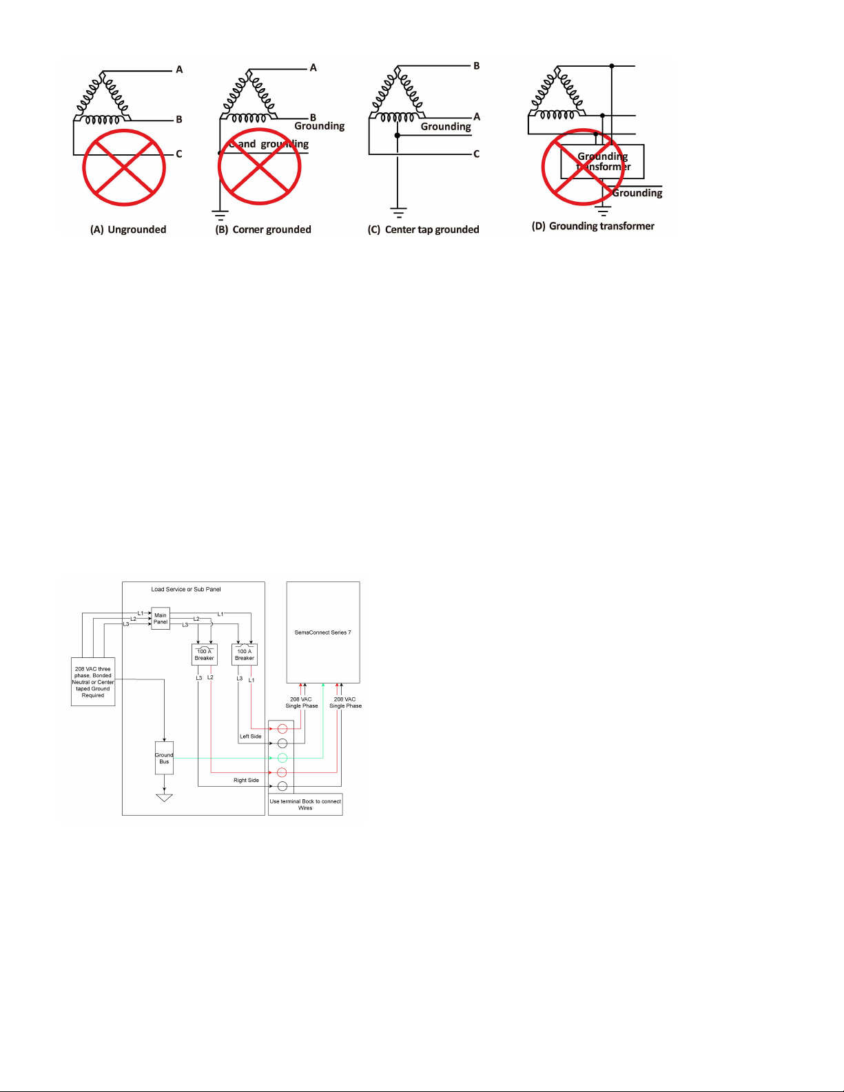
Wiring To System – Separate Power
Key Requirements
• Each EV charging station shall be on a dedicated electrical circuit.
• Each station shall be protected with a 100 Amp 2-pole common trip circuit breaker (non-GFCI type).
• Each station is designed to draw a maximum of 80 Amps.
• Each station can operate on either a 240V or 208V circuit.
• Each station requires five electrical supply wires (four hot, one ground, no neutral).
• All data communication is wireless, so there is no data cabling to install, but cellular communication is
required.
The figure below describes the wiring for installation of Series 7 Plus Charging Station on a separate power
circuit.
Installation Manuals Series 7 / 7 Plus EV Charging Station - 1
Copyright ©2021 SemaConnect, Inc. All rights reserved. Page 7 of 26
Installation Manuals Series 7 / 7 Plus EV Charging Station - 1
Copyright ©2021 SemaConnect, Inc. All rights reserved. Page 8 of 26

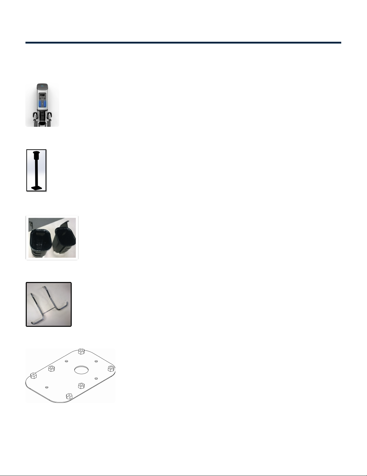
1.4.1. Parts List
Pedestal Installation
Series 7/Series 7 Plus Charging Station Head Unit
Pedestal Unit
Left and Right Cable Holster
Cable Rack
Charging Station Anchor Plate
Anchor J Bolts (4)
Installation Manuals Series 7 / 7 Plus EV Charging Station - 1
Copyright ©2021 SemaConnect, Inc. All rights reserved. Page 10 of 26

Pedestal Sacrificial Bolt
CMS Sacrificial Bolt
Head Unit Mounting Screws (4)
Pedestal Mounting Screws (4)
Holster Mounting Screws (4)
Installation Manuals Series 7 / 7 Plus EV Charging Station - 1
Copyright ©2021 SemaConnect, Inc. All rights reserved. Page 11 of 26
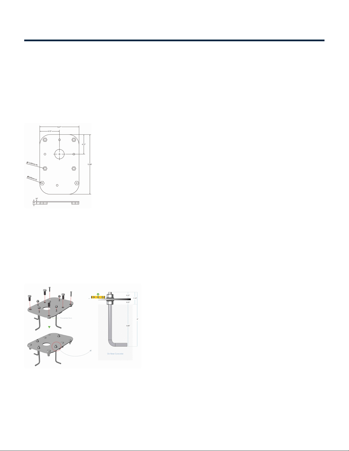
1.4.2. Anchor Plate Installation
Site Location
Select the location for the charging station. To mount the charging station, first prepare a concrete pad
properly aligned to the parking space. The concrete pad should be positioned such that the distance
between the charging station and electric vehicle is enough to minimize likelihood of damage.
Install Anchor Plate
Fit all J-Bolts (4), Pedestal (4) and CMS (2) Disposable Bolts to the anchor plate. (Figure-6)
• The flat side on which 6 nuts are welded on the Anchor Plate face downwards.
• Do not remove Disposable Bolts (6) from the anchor plate until the pedestal is ready to be installed.
• Make sure that only one thread of the top nut is visible after the J-Bolts are fitted to the anchor plate
(Figure 7)
Insert the anchor plate into the concrete (Figure-8).
• Ensure that at least 40” of wire extends out of the conduit.
• Insert the anchor plate into the concrete immediately after pouring the concrete.
• It is recommended to vibrate the concrete to eliminate any air bubbles.
Installation Manuals Series 7 / 7 Plus EV Charging Station - 1
Copyright ©2021 SemaConnect, Inc. All rights reserved. Page 12 of 26

• Anchor plate surface should be in level with the ground.
Note: Continuously check for the anchor plate until concrete sets to make sure that anchor plate does not
sink into the concrete
Installation Manuals Series 7 / 7 Plus EV Charging Station - 1
Copyright ©2021 SemaConnect, Inc. All rights reserved. Page 13 of 26
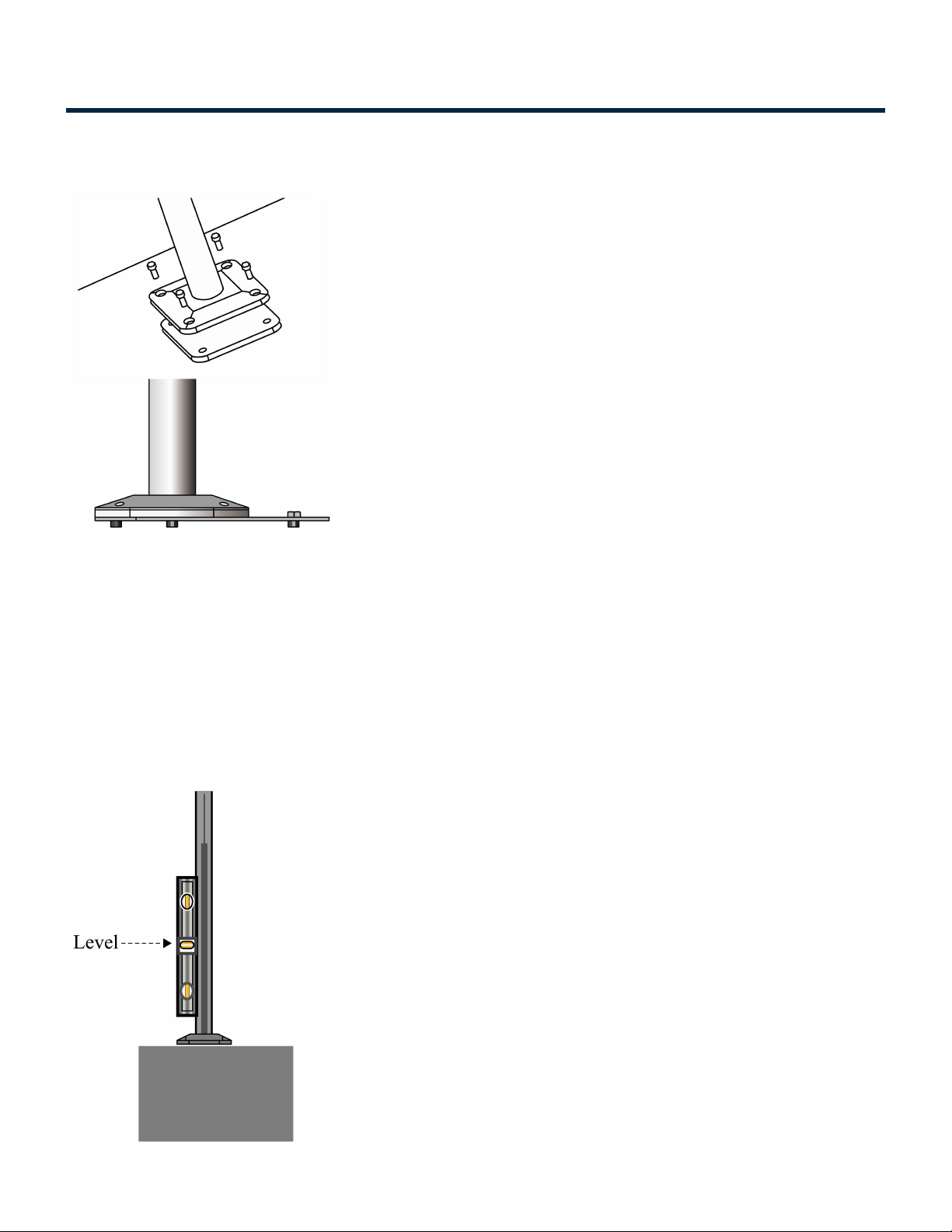
1.4.3. Pedestal Installation
Install the Pedestal
Now you are ready to install the Pedestal Unit. Carefully place the Pedestal Unit over the conduit and wires.
• Place the Pedestal Unit on the Anchor Plate such that the bolt holes are aligned.
• Ensure that the electric wires can be easily accessed through the access panel provided in the
Pedestal’s top section.
• Please ensure that access panel is to your right, when seen from the front end.
Anchor Bolts and Leveling Screws
Installation Manuals Series 7 / 7 Plus EV Charging Station - 1
Copyright ©2021 SemaConnect, Inc. All rights reserved. Page 14 of 26
First insert anchor bolts and secure with one or two turns, but do not tighten.
• The leveling screws that can be found on four sides are used to adjust for plumb.
• Adjust leveling screws to make pedestal plumb (check with Level at two points separated by 90
degrees).
• Gradually tighten anchor bolts to secure the Pedestal Unit to the Anchor Plate. Re-check for plumb.
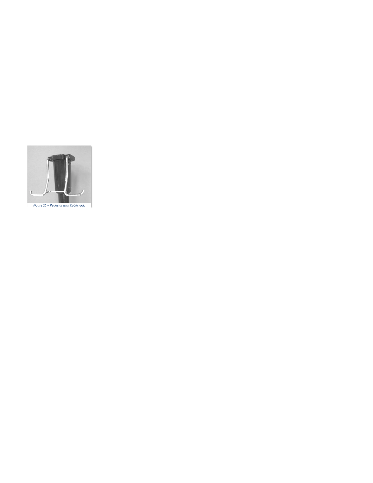
Attach Cable Rack
Loosen the cable rack mount screws. Now attach the Cable Rack to the Pedestal and tighten the screws.
Check that the Cable Rack is secure and is firmly attached to the Pedestal.
Installation Manuals Series 7 / 7 Plus EV Charging Station - 1
Copyright ©2021 SemaConnect, Inc. All rights reserved. Page 15 of 26
1.4.4. Charging Station Head Installation
Mount the Charging Station Head Unit
• Carefully place the charging station head unit on top of the pedestal as shown in the illustration.
• Align the Guide poles in the pedestal with the base of the head unit.
• Secure Charging station Head Unit to the Pedestal Unit with the help of four mounting screws
provided (two on front and one on each side).
• Ensure the charging station is plumb using a level. Check that the Head Unit is now securely fastened
to the Pedestal.
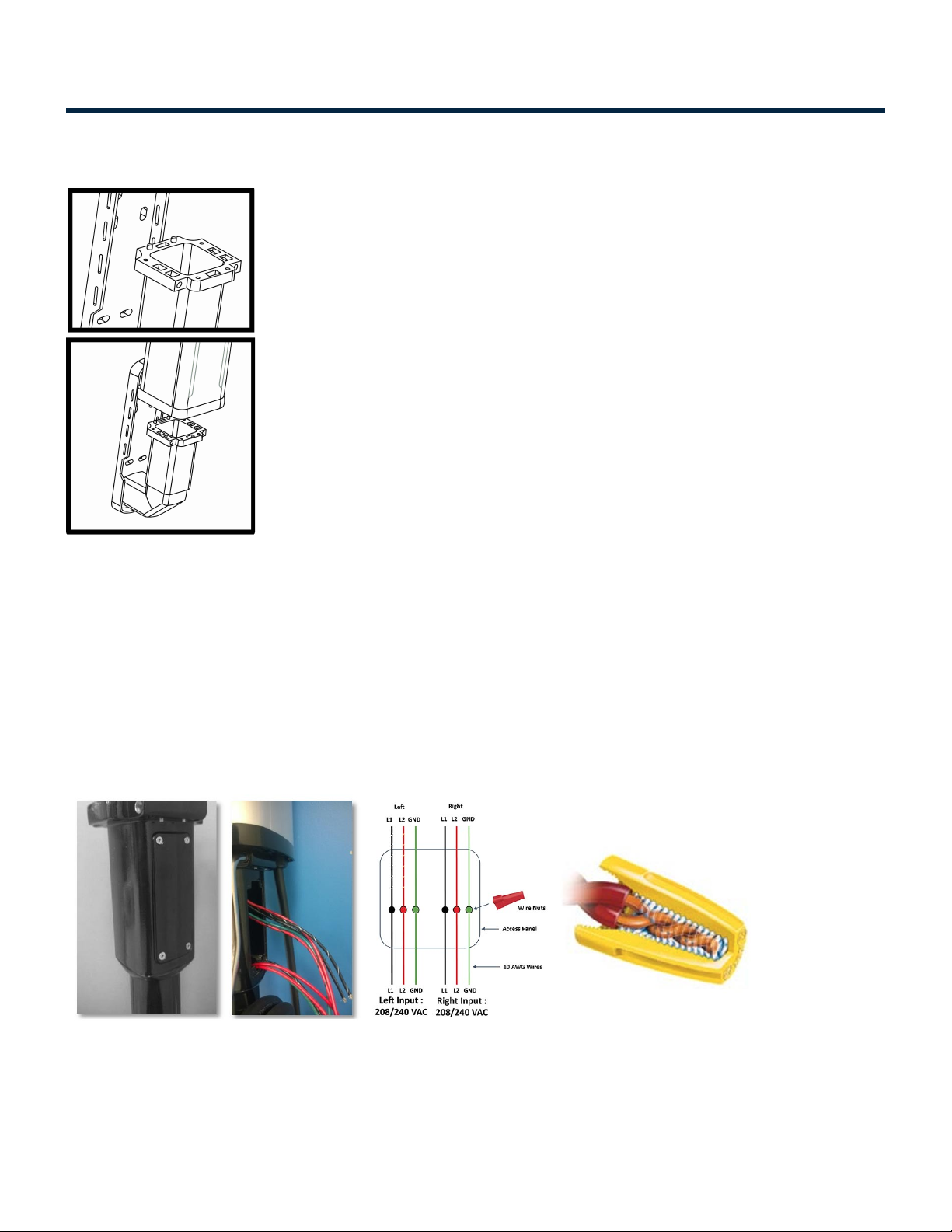
Connecting the Wires: Series 7
• Open the Access Panel by removing the four screws.
• Locate and access the wires inside.
• Carefully pull these wires a few inches outside of the access panel, to reveal 5 wires coming from the
Charging station Head Unit, Figure 13 (for Level-2 charging stations the color codes are Red, Black,
Installation Manuals Series 7 / 7 Plus EV Charging Station - 1
Copyright ©2021 SemaConnect, Inc. All rights reserved. Page 16 of 26

Red with Black stripe, Black with White stripe and Green) and 5 wires from the Pedestal with the
same color combination.
• Remove the insulation on each wire and prepare to connect those using wire-nuts.
• Match the wires using the colors (Black-Black, Green-Green & Red-Red) and connect them using wire
nuts as illustrated above.
• Also make sure that the striped wires are connected to the left side of the power source.
• Once connected, slowly insert the wires into the device and replace the access panel cover using the
screws previously removed.
CAUTION: Refer to the wire color codes and strictly adhere to this convention while connecting the charging
station and electrical supply wires. Incorrect wiring can lead to an electrical hazard.
Connecting the Wires: Series 7 Plus
• Open the Access Panel by removing the four screws.
• Locate and access the wires inside.
• Carefully pull these wires a few inches outside of the access panel, to reveal 5 wires coming from the
Charging station Head Unit, Figure 13 (for Level-2 charging stations the color codes are Red, Black,
Red with Black stripe, Black with White stripe and Green) and 5 wires from the Pedestal with the
same color combination.
• Remove the insulation on each wire and prepare to connect.
• Match the wires using the colors (Black-Black, Green-Green & Red-Red) and connect them using
terminal block.
• Also make sure that the striped wires are connected to the left side of the power source.
• Once connected, slowly insert the wires into the device and replace the access panel cover using the
screws previously removed.
CAUTION: Refer to the wire color codes and strictly adhere to this convention while connecting the charging
station and electrical supply wires. Incorrect wiring can lead to an electrical hazard.
Installation Manuals Series 7 / 7 Plus EV Charging Station - 1
Copyright ©2021 SemaConnect, Inc. All rights reserved. Page 17 of 26
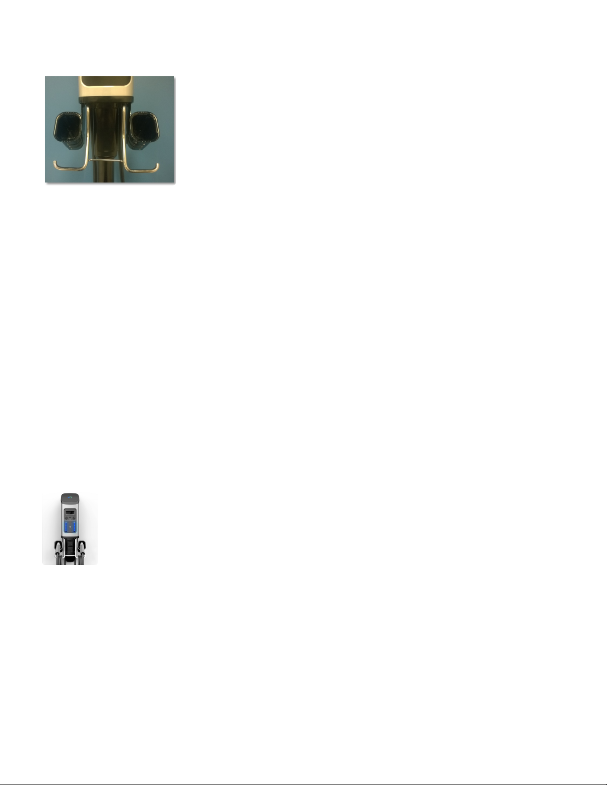
Install Holster
Attach the holster to the Head unit using the four (4) screws (2 for each side).
• Mounting points are located right next to cable rack, at the bottom of the charging stations
After tightening screws, check that the Holster is secure and is firmly attached to the Head Unit
Cleaning the Device
The device may be cleaned by following the instructions below:
• Use clean, soft cloth along with mild detergent to wash the dirt off.
• Do not use high pressure water. Pour water gently from the top and use a wet/dry cloth toclean all the
sides.
• Never use strong detergents or any other chemicals (Acids, petrol, thinner or any other solvent.)
• Do not exert too much of pressure on the device while cleaning.
• Do not open the device.
• Do not use a vacuum cleaner.
Power Up!
To power up, flip the breakers.
Call (800) 663-5633 to complete installation. Please have the station serial number ready with you. If you
do not have it, you can find it on left hand side of the station.
Installation Manuals Series 7 / 7 Plus EV Charging Station - 1
Copyright ©2021 SemaConnect, Inc. All rights reserved. Page 18 of 26
This manual suits for next models
1
Table of contents
Other Sema Connect Batteries Charger manuals


