Sema Connect 620 User manual

Sema Connect 620
Electric Vehicle Charging Station
Installation Guide
Page 1 Safety and Compliance
Page 2 Electrical Requirements
Page 4 Single-Pedestal & Dual-Pedestal Installation
Page 10 Wall/Pole Mount Installation
Contents
Sema Connect
Sema Connect, Inc.
4961 Tesla Drive, Bowie, MD 20715
semaconnect.com 1-800-663-5633 Revision #: 082017

Safety and Compliance
This document provides instructions on how to install the SemaConnect 620 Charging
Station only. This product must be installed in accordance with the
National Electrical Code (NEC) or the Canadian Electrical Code (CEC), whichever is
applicable. Consult a licensed contractor and/or electrician before installation to en-
sure compliance with local building practices, climate conditions, safety
standards, and state and local codes. Under no circumstances will compliance
with the information in this guide relieve the installer of responsibility to comply
with all applicable codes and safety standards.
This document describes the most common installation and mounting methods.
Contact SemaConnect Customer Support when it is not possible to perform an
installation using the procedures provided in this document. SemaConnect is not
responsible for damages that may occur during or as a result of installation.
IN NO EVENT SHALL SEMACONNECT, INC., OR ITS AUTHORIZED DISTRIBU-
TORS BE LIABLE FOR ANY INDIRECT, INCIDENTAL, SPECIAL, PUNITIVE, OR
CONSEQUENTIAL DAMAGES, INCLUDING WITHOUT LIMITATION, LOST
PROFITS, LOST DATA, LOSS OF USE, COST TO COVER, OR LOSS OR DAM-
AGE TO THE SEMACONNECT 620 CHARGING STATION ARISING OUT OF OR
RELATING TO THE USE OR INABILITY TO USE THIS GUIDE, EVEN IF
SEMACONNECT, INC., OR ITS AUTHORIZED DISTRIBUTORS HAVE BEEN
ADVISED OF THE POSSIBILITY OF SUCH DAMAGES.
SemaConnect 620 Charging Station is a trademark of SemaConnect, Inc. All other products or services
mentioned are the trademarks, service marks, registered trademarks, or registered service marks of their
respective owners. Copyright ©2017 SemaConnect, Inc. All rights reserved. This material is protected by
the copyright laws of the United States and other countries. It may not be modied, reproduced, or distrib-
uted without the prior, express written consent of SemaConnect, Inc.
semaconnect.com • 1-800-663-5633
1

semaconnect.com • 1-800-663-5633
Figure 1 Figure 2 Figure 3 Figure 4
This guide assumes that the appropriate wiring, conduit, and circuit protection are in place
at the installation site. Review this entire document to ensure you understand the installation
process before installing the SemaConnect 620 Charging Station.
Key Electrical Requirements
Wiring Diagram
Each charging station shall be on a dedicated electrical circuit.
Each station shall be protected with a 40-amp two-pole common trip circuit breaker.
(non-GFCI type).
Each station is designed to draw a maximum of 30-amps.
Each station can operate on either a 240V or 208V circuit.
Each station requires three electrical supply wires (two hot, one ground, no neutral).
Note: Data communications are wireless,so there is no data cabling.
Connect the SemaConnect 620 station to any one of the power sources as shown:
208 VAC three phase, Delta system, center tap grounded
208 VAC three phase, Wye system, center tap grounded
240 VAC single phase, bonded neutral.
In a Delta system, connect the SemaConnect 620 station only to a center-tapped ground-
ed transformer as shown above. Connect the station to the side where the ground is
bonded (in gure 3, line B and C). This allows voltage to remain constant regardless of
other loads that may be using the lines. Please do not connect to any of the other types
of power sources shown below.
2
semaconnect.com • 1-800-663-5633
SemaConnect 620 Single- &
Dual-Pedestal Mount Installation
Tools Required
Parts List
Mount and Parts List
Electrical Tools:
- Wire stripper, wire nut, and insulation tape
Mechanical Tool:
- Spirit level
Anchor Plate J-bolt:
- 3/8” inch wrench
Allen Driver Set:
- For Pedestal levelling – key size 3 (metric)
- For Pedestal Mounting – key size 10 (metric)
- For Head Unit Mounting Screw – key size 3 (metric)
- For Cable Rack – key size 2 (metric)
- For Access Panel – key size 2.5 (metric)
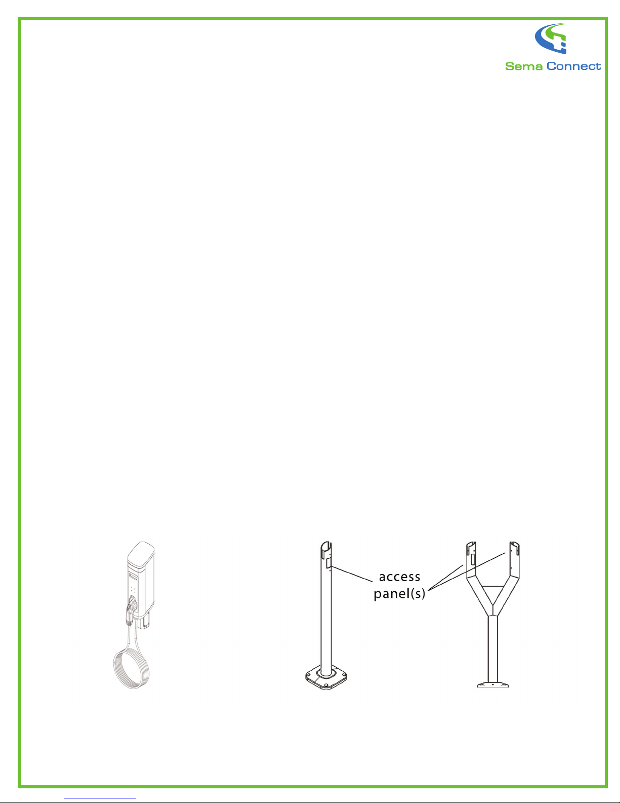
Part#1
Head Unit with J1772 Cable (20ft)
Qty Single: 1
Qty Double: 2
Part #2
Single Pedestal
Qty Single: 1
Qty Double: 0
Part #3
Dual Pedestal
Qty Single: 0
Qty Double: 1
3
SemaConnect 620 Single- & Dual-Pedestal
Mount Installation
Mount and Parts List
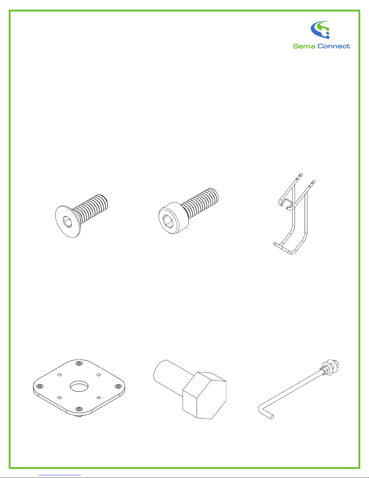
Part #4
Head Unit Mounting Screws
(M5x10 Socket Flat Head)
Qty Single: 4
Qty Double: 8
Part #7
Anchor Plate
Qty Single: 1
Qty Double: 1
Part #5
Pedestal Mounting Screw
(M12x25 Socket Head)
Qty Single: 4
Qty Double: 4
Part #8
Sacricial Bolts
Qty Single: 4
Qty Double: 4
Part #6
Cable Hanger
Qty Single: 1
Qty Double: 2
Part #9
Anchor J-bolt set–3/8” (3
nuts, 2 washers, 1 spring
washer, 1 J-bolt)
Qty Single: 4
Qty Double: 4
semaconnect.com • 1-800-663-5633 4

Mount and Parts List
5
SemaConnect 620 Single- & Dual-Pedestal
Mount Installation

semaconnect.com • 1-800-663-5633
SemaConnect 620 Single- & Dual-Pedestal Mount Installation
Figure 1
Figure 2
Follow the same procedure for both single- and dual-pedestal mount installation.
Anchor Plate Installation into Concrete
Step 1: Install the circuit breaker.
Caution: After the circuit breaker is installed, make sure it’s turned off.
Step 2: Prepare the site and construct a concrete form (typical footprint: 24”x24”). Run the electri-
cal conduit through the form. Please make sure that the electrical
conduit does not get in the way of the J bolts when installing the anchor plate.
Step 3: Place the wet concrete into the form and smooth it out.
Step 4: Attach all four anchor bolts (J-bolts) and four sacricial bolts to the anchor
plate (Figure 2).
Note 1: The nuts in the anchor plate should
face downward.
Note 2: Make sure that only one thread is
coming out of the top nut when the J bolt is
assembled to the anchor plate. If more
thread is coming out of the top nut, then the
installer will face problems while mounting
the pedestal.
6

semaconnect.com • 1-800-663-5633
SemaConnect 620 Single- & Dual-Pedestal Mount Installation
Figure 3
Step 5: Insert the anchor plate into the wet concrete.
Vibrate the concrete to get rid of any air bubbles.
Note: The anchor plate surface should provide a level surface for the
pedestal.
Step 6: Smooth out the concrete around the anchor plate.
Note: Make sure anchor plate sits on top of the concrete (Figure 3).
Step 7: Once the concrete has fully set, remove the sacricial bolts (Figure-4) from the anchor
plate. Then place the pedestal on top ofthe anchor plate and screw in four pedestal-mounting
screws (Figure 5). Do not tighten fully.
Note 1: Make sure the electrical wire is passed through the pedestal.
Note 2: Ensure that the access panel is to your right when its viewed from the front end.
7

semaconnect.com • 1-800-663-5633
SemaConnect 620 Single- & Dual-Pedestal Mount Installation
Figure 4
Preparing the SemaConnect 620 Head Unit
Assembly of SemaConnect 620 onto Pedestal
Step 8: Align the pedestal for plumb with the help of a set screw on the pedestal
(Figure 4). Once the pedestal is level, fully tighten the pedestal-mounting screw.
Step 9: Loosen the set screws in the head unit(s) and attach the cable rack to the
charging station (Figure 5).
Step 10: Remove the access panel from the head unit.
Step 11: Place the J1172 in the holder and hang the cable in the cable rack
Step 12: Now slide the head unit onto the pedestal and attach it with four mounting
screws (Figure 6).
Note: Make sure that the wires are not crushed between the pedestal and charging
station.
Step 13: Connect the three electrical supply wires.
Note: Strctly adhere to the wire color codes to ensure proper installation (green-green). Make sure
to use wire nuts and insulation tape for safety.
Step 14: Carefully push the wires in and attach the access plate (Figure 7).
8

semaconnect.com • 1-800-663-5633
Step 15: Power up the charging station by turning on the circuit breaker(s).
The station will automatically communicate with the network and initialize
itself using a cellular signal. A successful power-up is indicated by a steady
blue LED light and welcome message on the LCD screen.
Figure 6Figure 5 Figure 7
9
Step 16: Call (800) 663-5633 to nalize and complete the set-up and in-
stallation. Please have the station serial number ready. The station serial
number can be found on the left-hand side of the station.
SemaConnect Wall/Pole Mount Installation
semaconnect.com • 1-800-663-5633
Tools Required
Parts List
Electrical Tools
- Wire striper, wire nut, insulation tape
Mechanical Tools
- Power drill, level
Driver Set
- Head unit mounting screw, key size 3
- Cable rack, key size 2
- Access panel, key size 2.5
Wall mount bolt and pole mount strap are not supplied.
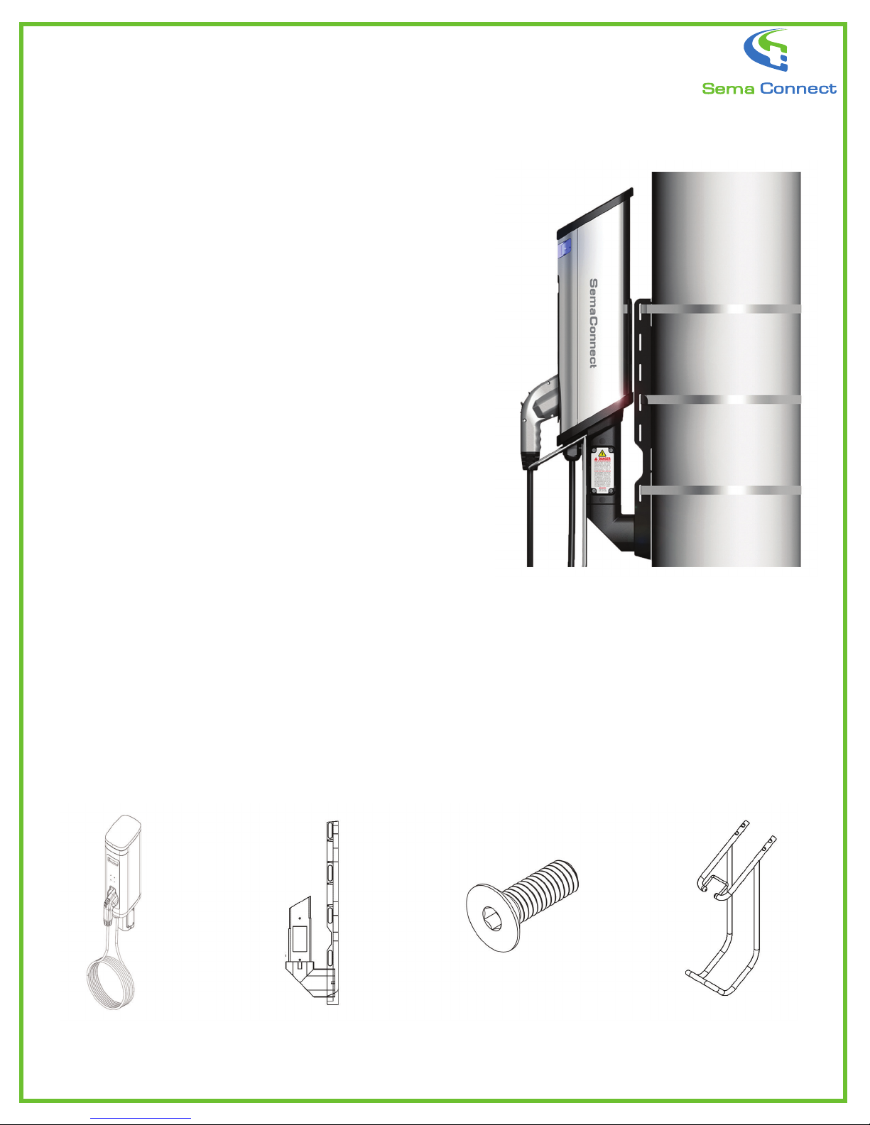
Part #1
Head Unit
Wall Mount: 1
Pole Mount: 1
Part #2
Wall/Pole Mount
Wall Mount: 1
Pole Mount: 1
Part #3
Head Unit Mounting Screws
(M4x10) at head)
Wall Mount: 4
Pole Mount: 4
Part #4
Cable Hanger
Wall Mount: 1
Pole Mount: 1
10

semaconnect.com • 1-800-663-5633
SemaConnect Wall- and Pole-Mount Installation
Follow the same procedure for both wall and pole mount installation.
Wall/Pole Mount Installation
Key Dimensions (In inches)
Step 1: Install the circuit breaker and run the electrical conduit.
Caution: After the circuit breaker is installed, make sure it’s turned off.
Step 2: Attach the wall/pole mount bracket. If a wall mount: Attach the Wall Mount Bracket to the
wall with four bolts. If a pole mount: Attach the Pole mount bracket with three straps.
In both cases, the electrical conduit can run from the back or the side.Make sure that the wall
mount is level.
Preparing the SemaConnect 620 Head Unit
Step 3: Loosen the set screws in the head
unit and attach the cable rack to the charging
station (Figure 1).
Step 4: Remove the access panel.
Step 5: Place the J1172 in the holder and hang
the cable in the cable rack (Figure 1).
11
semaconnect.com • 1-800-663-5633
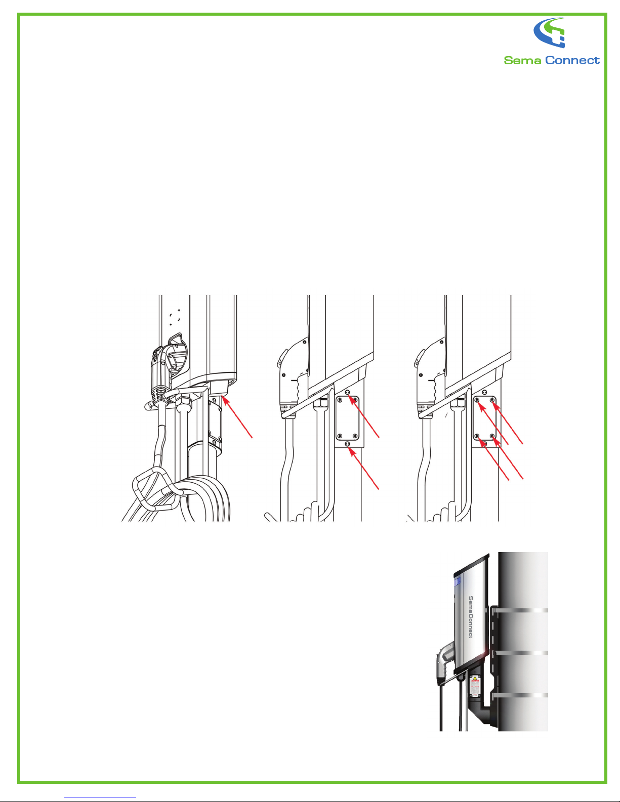
Assembly of the SemaConnect 620 onto a Wall/Pole Mount
Step 6: Now slide the head unit onto the wall/pole mount and attach it with
four mounting screws (Figure 2).
Caution: Make sure that the wires are not crushed between the
pedestal and charging station.
Step 7: Connect the three electrical supply wires.
Caution: Stirictly adhere to the wire color codes to ensure
proper installation. Make sure to use wire nuts and insulation
tape for safety.
Step 8: Carefully push the wires in and attach the access plate (Figure 3).
Step 9: Power up the charging station by turning on the cir-
cuit breaker(s). The station will automatically communicate
with the network and initialize itself using a cellular signal. A
successful power-up is indicated by a steady blue LED light
and welcome message on the LCD screen.
Step 16: Call (800) 663-5633 to nalize and complete the
set-up and installation. Please have the station serial num-
ber ready. The station serial number can be found on the
left-hand side of the station.
Figure 1 Figure 2 Figure 3
12
Table of contents
Other Sema Connect Batteries Charger manuals


