Semtech SX1211-11SKA User manual

ADVANCED COMMUNICATIONS & SENSING
User’s Guide
SX1211-11SKA
SX1211-11SKA
User’s Guide: Advanced Mode
Revision 0.1 March 2009 © 2009 Semtech Corp. www.semtech.com
1

ADVANCED COMMUNICATIONS & SENSING
User’s Guide
SX1211-11SKA
Table of Contents
1Introduction ................................................................................................................................................... 4
2Getting Started .............................................................................................................................................. 5
2.1 Kit Contents..................................................................................................................................................... 5
2.2 Installation....................................................................................................................................................... 5
2.3 SX1211SKA Overview.................................................................................................................................... 6
3Quick Start Guide.......................................................................................................................................... 7
3.1 SX1211SKA Quick Start (All Modes).............................................................................................................. 7
3.2 SX1211SKA Receive Mode Configuration...................................................................................................... 9
3.3 SX1211SKA Transmit Mode Configuration................................................................................................... 10
4SX1211SXA Software Description............................................................................................................. 11
4.1 Overview ....................................................................................................................................................... 11
4.2 File Menu....................................................................................................................................................... 11
4.3 Shortcut Buttons............................................................................................................................................ 12
4.4 Text Field Conventions for the SX1211SKA................................................................................................. 13
4.5 McParam Tab................................................................................................................................................ 13
4.6 Overview Panel............................................................................................................................................. 15
4.7 Register Hexadecimal Display...................................................................................................................... 15
4.8 The Mode Control Box.................................................................................................................................. 16
4.9 The IrqParam Tab......................................................................................................................................... 17
4.10 The RxParam Tab......................................................................................................................................... 17
4.11 The TxParam Tab ......................................................................................................................................... 19
4.12 The OscParam Tab....................................................................................................................................... 20
4.13 The Packet Test Tab..................................................................................................................................... 20
5Schematics and 2-Layer PCB Layout: SX1211SKA................................................................................. 23
6References................................................................................................................................................... 25
Revision 0.1 March 2009 © 2009 Semtech Corp. www.semtech.com
2

ADVANCED COMMUNICATIONS & SENSING
User’s Guide
SX1211-11SKA
Table of Figures
Figure 1. SX1211 Application Circuit .............................................................................................................................4
Figure 2. SX1211SKA Contents.....................................................................................................................................5
Figure 3. SX1211SKA Board Picture.............................................................................................................................6
Figure 4. SX1211 User Interface, Default Settings........................................................................................................7
Figure 5. The New SX1211 Configuration: Ready to be Written...................................................................................8
Figure 6. The SX1211SKA User Interface whilst in Packet Receiver Mode..................................................................9
Figure 7. The SX1211SKA User Interface Ready to Transmit the Demonstration Packet..........................................10
Figure 8. SX1211SKA GUI Overview and References to the User Guide Description of this Chapter.......................11
Figure 9. Example Text Editor Output of the SX1211 Configuration File ....................................................................12
Figure 10. SX1211 Local Oscillator Generation...........................................................................................................15
Figure 11. The Overview Panel....................................................................................................................................15
Figure 12. The Hexadecimal Register Display Summary............................................................................................16
Figure 13. The Mode Control Box also Incorporates RSSI.........................................................................................16
Figure 14. The Interrupt Mapping Display....................................................................................................................17
Figure 15. SX1211 Receiver Block Diagram, the Colours Correspond to the Frequency of Operation......................17
Figure 16. Receiver Parameter Display.......................................................................................................................18
Figure 17. SX1211 Simplified Transmitter Block Schematic Diagram.........................................................................19
Figure 18. The Transmitter Parameter Tab Display.....................................................................................................19
Figure 19. The Oscillator Parameter Display...............................................................................................................20
Figure 20. The Packet Receiver / Transmitter Test Display ........................................................................................21
Figure 21. Software Display: Successful Packet Mode Reception..............................................................................22
Revision 0.1 March 2009 © 2009 Semtech Corp. www.semtech.com
3

ADVANCED COMMUNICATIONS & SENSING
User’s Guide
SX1211-11SKA
1 Introduction
The SX1211 is a single chip transceiver IC designed for operation in the European 868 MHz and U.S. 915 MHz
licence free ISM bands. The SX1211 is optimized for very low power consumption (3mA in receiver mode). It
incorporates a baseband modem with data rates up to 200 kb/s. Data handling features include a sixty-four byte
FIFO, packet handling, automatic CRC generation and data whitening. Its highly integrated architecture allows for
minimum external component count whilst maintaining design flexibility. All major RF communication parameters are
programmable and most of them may be dynamically set.
The SX1211SKA is a USB evaluation tool designed to allow simple and easy evaluation of the suitability of the
SX1211 for a given application. The low component count reference design implemented in the SX1211SKA is
shown below:
Figure 1. SX1211 Application Circuit
The SX1211 main features include:
¾Low Rx power consumption: 3mA
¾Low Tx power consumption: 25 mA @ +10 dBm
¾Good reception sensitivity: down to -107 dBm at 25 kb/s in FSK, -113 dBm at 2kb/s in OOK
¾Programmable RF output power: up to +12.5 dBm in 8 steps
¾Packet handling feature with data whitening and automatic CRC generation
¾Wide RSSI (Received Signal Strength Indicator) dynamic range, 70dB from Rx noise floor
¾Bit rates up to 200 kb/s, NRZ coding
¾On-chip frequency synthesizer
¾FSK and OOK modulation
¾Incoming sync word recognition
¾Built-in Bit-Synchronizer for incoming data and clock synchronization and recovery
Revision 0.1 March 2009 © 2009 Semtech Corp. www.semtech.com
4

ADVANCED COMMUNICATIONS & SENSING
User’s Guide
SX1211-11SKA
2 Getting Started
2.1 Kit Contents
As illustrated in the figure below, the SX1230-11SKA Evaluation kit is composed of:
¾A pair of SX1211SKA boards
¾SX1211-11SKA CDROM including all necessary PC software and documentation
Figure 2. SX1211SKA Contents
2.2 Installation
SX1211SKA Advanced Mode Software Installation
1- Put the CDROM in your computer and browse the contents of the CD.
2- Open the “sx1211starterkitsetupweb.exe” manually. It can be found in the \Installers sub directory of the
CD-ROM.
3- Follow installation guidelines until the process is completed. Please note that .NET Framework 2.0 and the
FTDI USB driver will be automatically installed if not detected on your computer.
4- Connect the SX1211SKA board to the PC via the USB interface.
5- Launch “SX1211SKA” from the Start menu.
6- Click on “Connect” button in toolbar or in File menu.
7- SX1211SKA is now installed and ready to be used.
Revision 0.1 March 2009 © 2009 Semtech Corp. www.semtech.com
5
ADVANCED COMMUNICATIONS & SENSING
User’s Guide
SX1211-11SKA
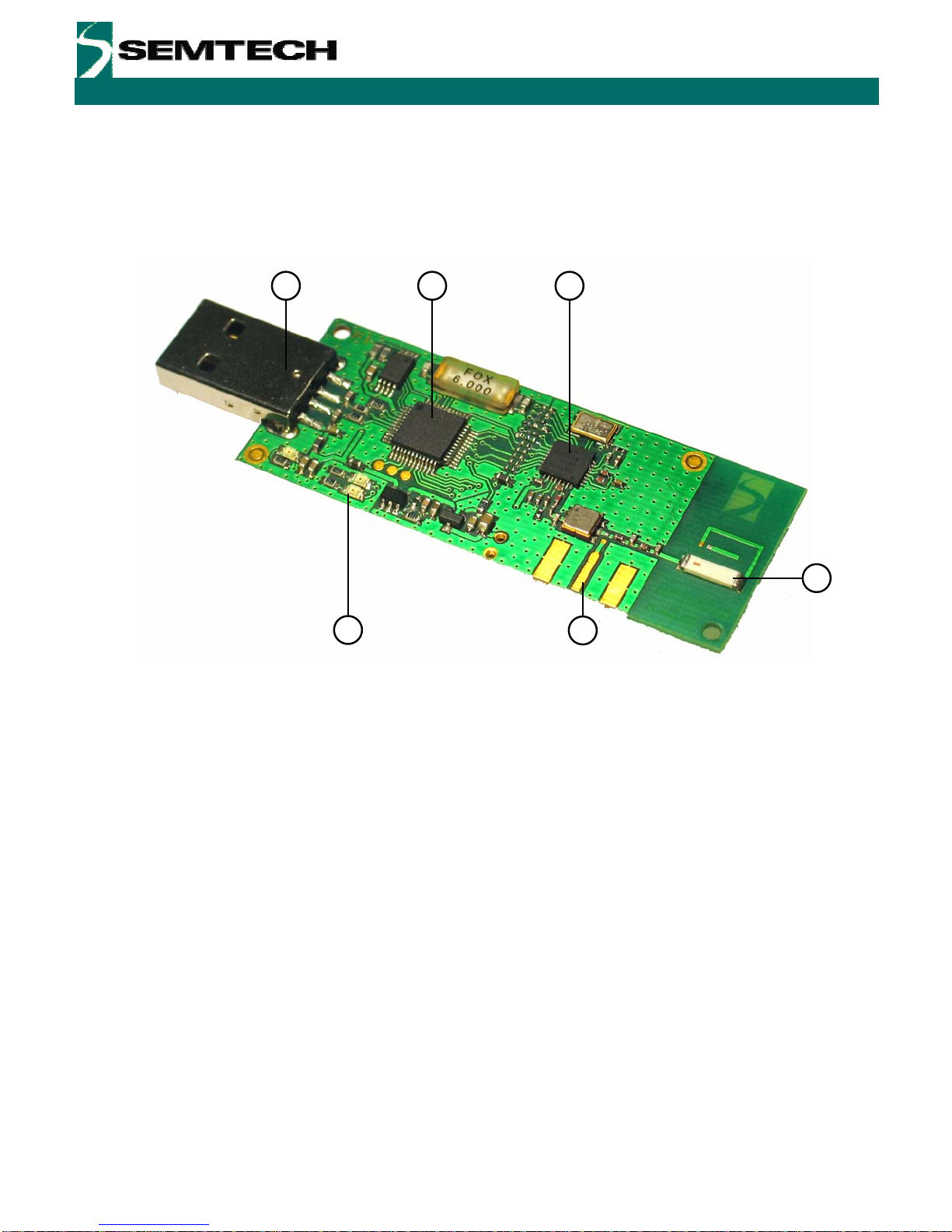
2.3 SX1211SKA Overview
The SX1211SKA features the SX1211 reference design (1) and is also interfaced via an FTDI bridge (6) to the USB
type ‘A’ interface (5) of a host PC. Indication of transmission and reception is indicated on a pair of LEDs (4). A
Johanson Technologies ceramic antenna is employed (2) and optional provision for an SMA connector (not
populated) is provided for laboratory testing.
2
3
1
4
65
Figure 3. SX1211SKA Board Picture
Revision 0.1 March 2009 © 2009 Semtech Corp. www.semtech.com
6
ADVANCED COMMUNICATIONS & SENSING
User’s Guide
SX1211-11SKA
3 Quick Start Guide
With the SX1211SKA software installed, follow the sequence below to establish communication between the one
SX1211SKA as transmitter and one SX1211SKA as receiver.
3.1 SX1211SKA Quick Start (All Modes)
1. Plug the SX1211SKA into the USB port of the computer.
2. Run the SX1211 User Interface software Start > All Programs > SX1211SKA > SX1211SKA
3. The SX1211SKA should connect automatically to the User Interface
Software. If not, then click on the USB connect short-cut button, located in
the top left hand corner of the window.
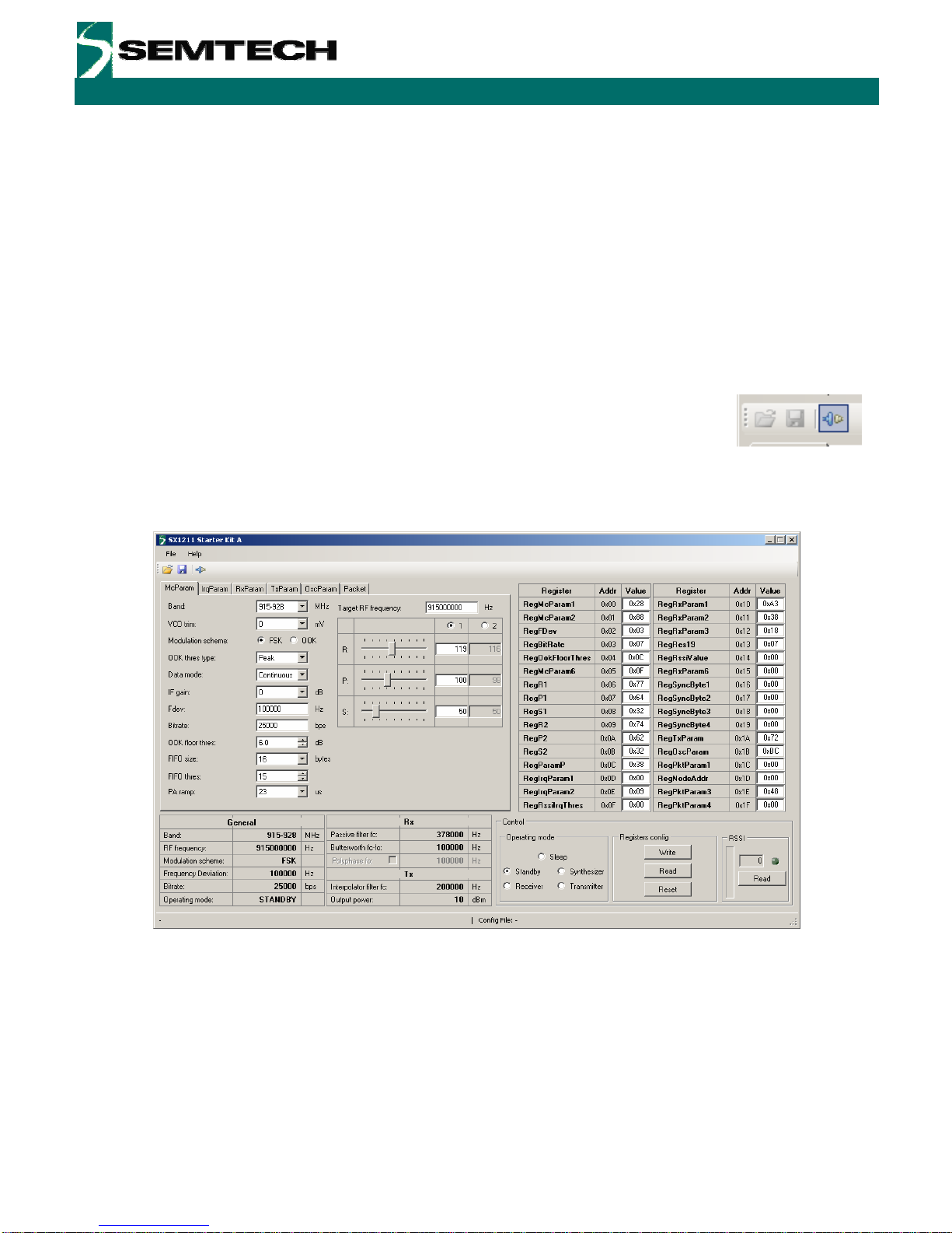
4. Once connected the SX1211SKA shows the default configuration of the SX1211 register settings
upon power-up.
Figure 4. SX1211 User Interface, Default Settings
5. Once connected the SX1211SKA shows the default configuration of the SX1211 register settings
upon power-up (as shown in Figure 4).
Revision 0.1 March 2009 © 2009 Semtech Corp. www.semtech.com
7
ADVANCED COMMUNICATIONS & SENSING
User’s Guide
SX1211-11SKA
6. The settings for communication between transceiver kits are located on the
installation CD-ROM provided with the kit. Use the File > Open from the menu
bar, or the open short-cut button to load a configuration file.
7. Load the “XXX_SX1211_pingpong.cfg” file from the “SX1211 Demo Files” folder on the CD-ROM.
Where XXX corresponds to the frequency band of the SX1211SKA (either 868 or 915 MHz).
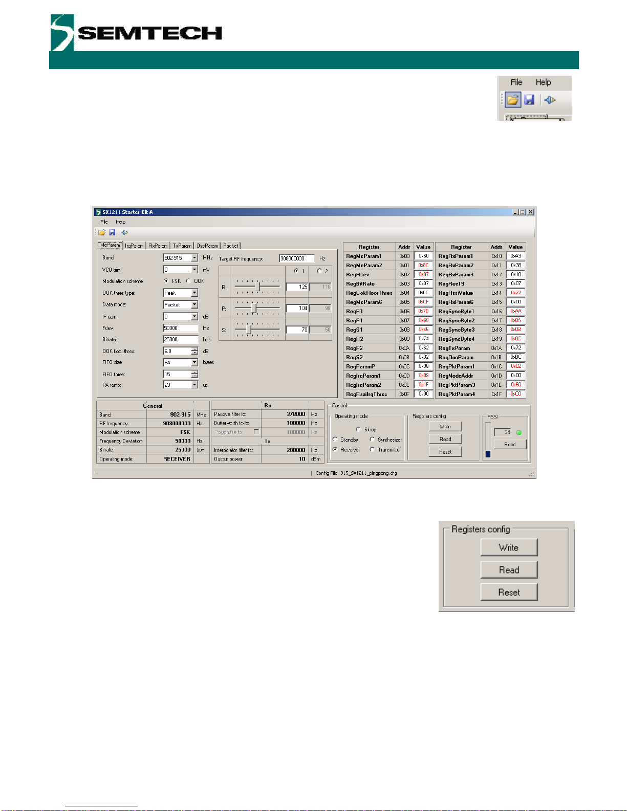
8. The display will then appear as shown in Figure 5.
Figure 5. The New SX1211 Configuration: Ready to be Written
9. By clicking on the write button in the ‘Registers config’ section, the
new register values are written to the SX1211 registers. If
successful, the red values in the hexadecimal register summary
table will turn black. As a double check, the register read button
may be pressed – the values presented on the user interface
should remain unchanged.
Revision 0.1 March 2009 © 2009 Semtech Corp. www.semtech.com
8

ADVANCED COMMUNICATIONS & SENSING
User’s Guide
SX1211-11SKA
3.2 SX1211SKA Receive Mode Configuration
1. Click on the ‘Packet’ tab to access the packet testing portion of the program. Within this window a pre-
defined packet structure is already configured. It remains simply to click the ‘Reception’ radio button and
press the Start button. At this point the SX1211SKA enters packet receive mode and is now listening for
valid packets. At this juncture another SX1211SKA must be configured as transmitter.
Figure 6. The SX1211SKA User Interface whilst in Packet Receiver Mode
Revision 0.1 March 2009 © 2009 Semtech Corp. www.semtech.com
9

ADVANCED COMMUNICATIONS & SENSING
User’s Guide
SX1211-11SKA
3.3 SX1211SKA Transmit Mode Configuration
1. Repeat steps 1 to 9 of Section 3.1 with the second SX1211SKA provided in the kit. Then click on
the ‘Packet’ tab.
2. The packet test display is preconfigured in transmit mode with a valid payload (see Figure 7). The
‘Repeat value’ may be edited according to the number of packets desired to be transmitted (leave
equal to zero for continuous transmission).
3. Press the Start button. Packets will start to be sent, the ‘Tx Packets’ display indicating the number
of packets sent.
4. The successful reception of packets will be indicated in the ‘Rx packets’ window of the receiver
SX1211SKA.
Figure 7. The SX1211SKA User Interface Ready to Transmit the Demonstration Packet
Revision 0.1 March 2009 © 2009 Semtech Corp. www.semtech.com
10
ADVANCED COMMUNICATIONS & SENSING
User’s Guide
SX1211-11SKA
4 SX1211SXA Software Description
4.1 Overview
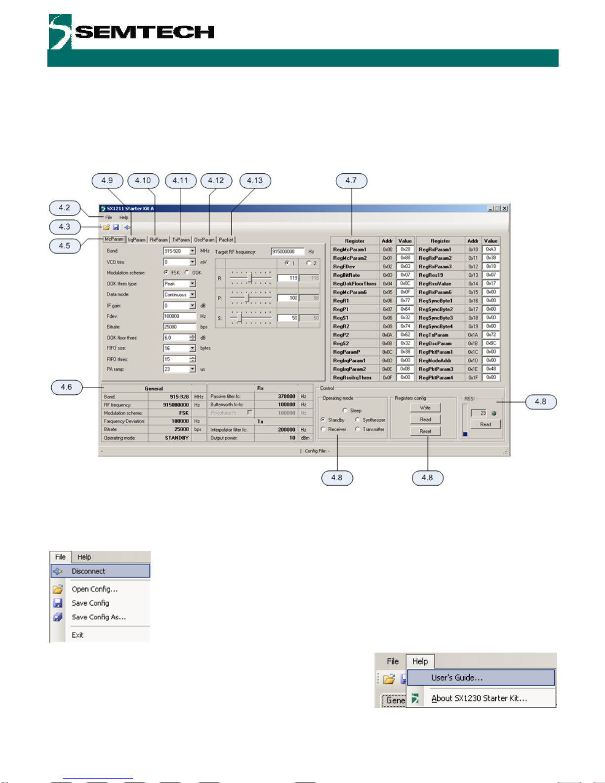
Figure 8 shows the SX1211SKA graphical user interface. Each of the numbers surrounding the display corresponds
to the Chapter within this section which corresponds to the description of that GUI feature.
Figure 8. SX1211SKA GUI Overview and References to the User Guide Description of this Chapter
4.2 File Menu File menu contains some general purpose functions. Some of them can also be accessed
on the toolbar by clicking directly on the icon. The first feature in the list provides the
possibility of connecting or disconnecting to the USB kit. Care must be taken to ensure that
the USB port is closed before removing the USB kit. This functionality may also be
accessed through the short cut buttons (see Section 4.3).
The possibility of opening configuration files and saving the present configuration is also
provided. This is done through a standard Windows file dialog box.
The Help menu contains two menu items. The first item provides a link
to this user guide in PDF format. The second, About SX1230 Starter
kit…, gives information in the revision of the software installed.
Revision 0.1 March 2009 © 2009 Semtech Corp. www.semtech.com
11
ADVANCED COMMUNICATIONS & SENSING
User’s Guide
SX1211-11SKA
4.3 Shortcut Buttons
The shortcut buttons provide identical functionality to those listed under the file menu
The configuration file open shortcut button. This opens a windows file dialog box to allow access to
previously saved SX1211 register configuration files.
The save configuration file shortcut button immediately saves and overwrites the existing
configuration file.
The connect / disconnect button allows the user to manage manually connection and
disconnection of the kit. Note that any time the SX1211SKA is to be removed from the system; the
kit must first be disconnected.
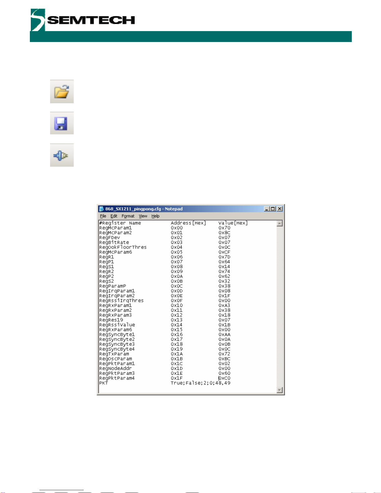
The saved configuration files are designed to be a useful tool for embedded software development. The file can be
opened in any text editor to display the programmed register name, address and hexadecimal value programmed to
that address.
Figure 9. Example Text Editor Output of the SX1211 Configuration File
Revision 0.1 March 2009 © 2009 Semtech Corp. www.semtech.com
12

ADVANCED COMMUNICATIONS & SENSING
User’s Guide
SX1211-11SKA
4.4 Text Field Conventions for the SX1211SKA
An orange background highlight indicates that the precise
value entered into the data entry field is not directly
addressable by the SX1211. Instead the closest
(rounded) value will be used.
Conversely a red background highlight indicates where
the maximum or minimum value for that register
parameter has been exceeded.
4.5 McParam Tab
Band Selection One of the three operating bands for the SX1211 may be selected
here. The SX1211SKA hardware is band specific and so the
corresponding band should be selected.
VCO Voltage Trim
In some designs the VCO voltage requires trimming. The
SX1211SKA reference design does not require this function, but is
included here for completeness.
Modulation Selection
The SX1211 is capable of both FSK and OOK modulation, they are
selectable through the user interface by clicking with the mouse on
the appropriate radio button.
OOK Receiver Detection Type
Several modes of OOK detection are possible, please see the
SX1211 datasheet for mode information on configuring the OOK
receiver.
Data Mode
Three data modes are available for the SX1211, typically packet
mode is selected automatically, requiring no user selection, upon
launching the Packet Test (see Section 4.13).
Gain of the IF Stage
The gain of the intermediate frequency amplifier chain can be
adjusted manually.
Revision 0.1 March 2009 © 2009 Semtech Corp. www.semtech.com
13
ADVANCED COMMUNICATIONS & SENSING
User’s Guide
SX1211-11SKA
Frequency Deviation
Text entry field for the frequency deviation when using FSK
modulation.
Bit Rate
The bit rate of the transmitted signal (in bps) can be directly edited
in this data entry field.
Floor Threshold for OOK Detection
Margin to the OOK demodulation threshold – see SX1211
datasheet for more details.
FIFO Settings
Both the working size of the FIFO and the number of bytes it must
store before generating a hardware interrupt are user defined.
Again this functionality is largely automated in the packet test
mode (Section 4.13).
PA Ramping
The PA ramp rise time is selectable from the list of programmable
values.
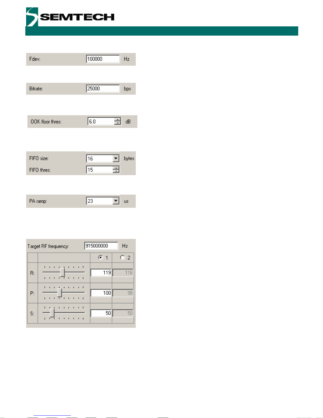
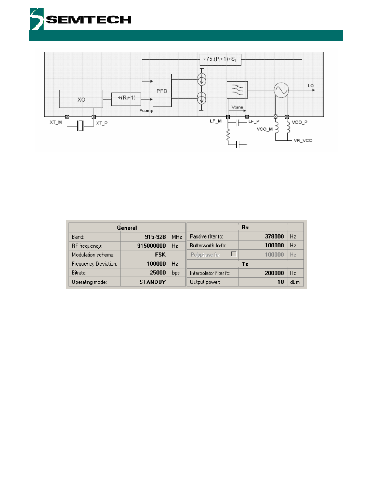
Frequency of Operation
The frequency of operation of the SX1211 is a set by three
frequency divider ratios (see Figure 10). Based upon the frequency
of the crystal oscillator and the values of these divider ratios the
local oscillator frequency may be determined.
To simplify this process, the SX1211SKA user interface sees this
process completely automated. By entering the desired operating
frequency in the text field at the top of the display, the resultant R,
P and S divider ratios are calculated (see the SX1211 datasheet
for information on their calculation).
Revision 0.1 March 2009 © 2009 Semtech Corp. www.semtech.com
14
ADVANCED COMMUNICATIONS & SENSING
User’s Guide
SX1211-11SKA
Figure 10. SX1211 Local Oscillator Generation
4.6 Overview Panel
A summary of the values presently entered into the user interface software is shown in the overview display at the
bottom of the screen. This is sub-divided into three sections pertaining to: general configuration, transmitter settings
and receiver parameters.
Figure 11. The Overview Panel
4.7 Register Hexadecimal Display
Figure 12 shows the register summary of the SX1211. In addition to manual user entry in the fields described in the
previous section, direct hexadecimal entries may be made into the register display. Note that values yet to be written
to the SX1211 registers appear in red. Note, also, that for full control flexibility, incorrect (red) values entered in the
hexadecimal section will still be written in the event of a register ‘write’. So care must be exercised when editing the
hexadecimal values.
Revision 0.1 March 2009 © 2009 Semtech Corp. www.semtech.com
15

ADVANCED COMMUNICATIONS & SENSING
User’s Guide
SX1211-11SKA
Figure 12. The Hexadecimal Register Display Summary
4.8 The Mode Control Box
The mode control box is sub-divided into three sections. The first ‘Operating mode’ allows the user to change the
operating mode of the SX1211 by clicking on the radio button corresponding to the desired mode. Note that the
transition between modes is instantaneous. The centre section, ‘Registers config’ allows the register settings
entered elsewhere in the user interface to be written to the configuration registers of the SX1211 by clicking the
write button. The read operation will read the configuration registers and refresh the user interface display with the
values read from the SX1211.
Figure 13. The Mode Control Box also Incorporates RSSI
The third, rightmost, section of the mode control box allows an instantaneous RSSI (received signal strength
indicator) measurement. Please note that this feature is only accessible when the SX1211 is in the receiver
operating mode.
Revision 0.1 March 2009 © 2009 Semtech Corp. www.semtech.com
16
ADVANCED COMMUNICATIONS & SENSING
User’s Guide
SX1211-11SKA
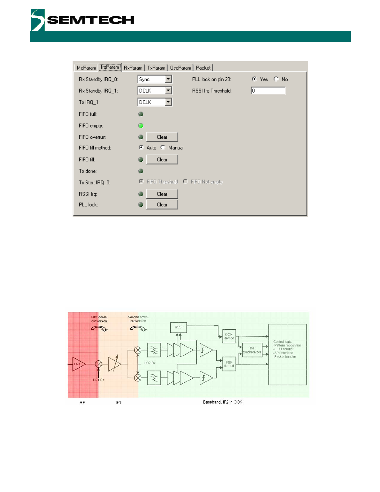
4.9 The IrqParam Tab
Figure 14. The Interrupt Mapping Display
For total register coverage by the user interface, the interrupt mapping for the SX1211 can be controlled through the
configuration of the IrqParam display. Note, however, that the hardware interrupt feature is not used directly by the
GUI. For further information please see the corresponding register descriptions in the SX1211 datasheet and the
PCB layout and schematics of Section 5.
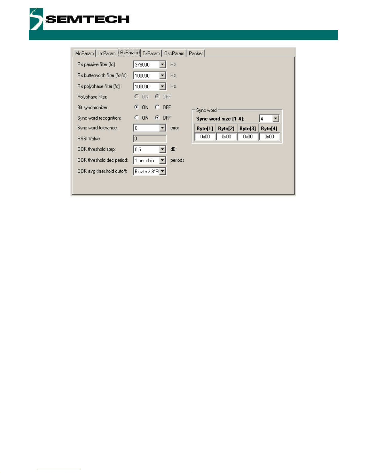
4.10The RxParam Tab
The receiver parameter field provides full access to all of the software configurable settings of the SX1211. For
reference, a simplified block schematic of the SX1211 receiver is shown in figure Figure 15. The settings
configurable in the receiver parameter tab correspond to the programmable baseband receiver functions.
Figure 15. SX1211 Receiver Block Diagram, the Colours Correspond to the Frequency of Operation.
Revision 0.1 March 2009 © 2009 Semtech Corp. www.semtech.com
17
ADVANCED COMMUNICATIONS & SENSING
User’s Guide
SX1211-11SKA
Figure 16. Receiver Parameter Display
For a complete description of the functionality of the receiver section please consult the SX121 datasheet. However,
the principle fields of interest for general use are:
Rx Filters:
The first three text entry fields of the receiver parameters correspond to the baseband filtering section. Note that the
Butterworth filter is the narrowest of the three filters and determines the receiver channel bandwidth.
Bit Synchroniser:
This block performs timing recovery and synchronises the decision on whether a given bit is logical high or low
based upon the received bit stream. This block yields a substantial improvement in receiver sensitivity performance
and it is hence recommended that it be left enabled.
Sync Word:
The synchronisation word is applicable to operation in buffered and packet modes. For packet mode operation the
sync word is set using the packet editor – this may be found in the ‘Packet’ Tab (Section 4.13). Link testing by the
SX1211SKA is done in packet mode only – sync word provision is made here for completeness.
OOK Settings:
OOK demodulation is based upon measurements from the RSSI block and there are a rich variety of settings for
how the OOK signal is detected and processed. These techniques and the corresponding settings are given a
detailed treatment in the SX1211 datasheet.
Revision 0.1 March 2009 © 2009 Semtech Corp. www.semtech.com
18

ADVANCED COMMUNICATIONS & SENSING
User’s Guide
SX1211-11SKA
4.11 The TxParam Tab
The transmitter configuration of the SX1211 is shown in Figure 17. This shows that the modulating signal is
generated by direct digital synthesis (DDS), unconverted through the superheterodyne mixer stages and then
amplified by a power amplifier chain.
Figure 17. SX1211 Simplified Transmitter Block Schematic Diagram
Figure 18. The Transmitter Parameter Tab Display
The two parameters which are configurable for transmit operation of the SX121 are:
Output Power:
The output power of the SX1211 can be programmed in 3 dB steps. Valid programmable powers are selected from
a drop-down list of valid values.
Interpolation Filter Setting:
The DDS output requires filtering to remove the spurii common in the generation of signals through this technique;
this is performed by the interpolation filters. The cut-off frequency of the interpolation filters can be selected from the
drop down menu of valid values. The technique for calculating the cut-off frequency may be found in the SX1211
datasheet.
Revision 0.1 March 2009 © 2009 Semtech Corp. www.semtech.com
19

ADVANCED COMMUNICATIONS & SENSING
User’s Guide
SX1211-11SKA
4.12The OscParam Tab
Figure 19. The Oscillator Parameter Display
The oscillator parameter display gives access to the clock output functionality. This can be enabled or disabled and
the frequency changed by entering a value in the ‘CLK out frequency’ text field. Note also that there is provision to
change the frequency of the crystal. Changing of the crystal frequency has a knock on effect on all parameters that
are a function of the reference frequency, for example bit rate, filter settings, RF output frequency. The SX1211SKA
is fitted with the 12.8 MHz crystal recommended in the SX1211 reference design. For this reason the crystal value
should, typically, be left unchanged.
4.13 The Packet Test Tab
The ‘Packet’ tab is the principle interface for conducting transmission or reception testing. The display, as shown in
Figure 18 is divided into three horizontal portions. The top portion of the display is given to the packet editor. Here
the configuration of the packet, either to be transmitted or received by the SX1211SKA is constructed.
The packet layout contains all of the features described in the SX1211 datasheet. This includes:
Preamble
This input allows the user enable and set the length of a pulse train preamble (sent at the data rate).
Sync word size
A custom syncronisation word of up to 4 bytes may also be added.
Sync tol
The number of errors which may be accommodated in the sync word (bits), before the packet is rejected.
Format / Length / Address
Fixed or variable length packets may also be stipulated (see the SX1211 datasheet for more information), as may
an optional 1 byte address.
Digital Coding
Optional channel coding including CRC, data whitening and Manchester coding are also available.
With these options entered the constructed packet is shown in the ‘Packet’ frame. Where the SX1211SKA is to be
used in transmit mode, the packet payload may also be edited in either ASCII or hexadecimal. Packet transmission
is enabled by selecting the ‘Transmission’ radio button. This starts when the ‘Start’ button is pressed. Either infinite
transmission (repeat value = 0) or a finite number of packets may be transmitted by editing the repeat value.
Revision 0.1 March 2009 © 2009 Semtech Corp. www.semtech.com
20
Table of contents
Other Semtech Motherboard manuals

Semtech
Semtech SX1211SK915 User manual

Semtech
Semtech Lora Mote User manual

Semtech
Semtech EB-GS2971 User manual

Semtech
Semtech LoRa Edge LR1110 User manual

Semtech
Semtech SX9306 User manual

Semtech
Semtech GS3440 User manual

Semtech
Semtech SX8651EVK User manual

Semtech
Semtech SC120 User manual
Semtech
Semtech LoRa Edge Tracker Reference Design Evaluation... User manual

Semtech
Semtech TSWITX-12V-EVM User manual


