Semtech SX8651EVK User manual

SX8651EVK
www.semtech.com
Page 1
ADVANCED COMMUNICATIONS & SENSING
USER GUIDE
Revision V1.2/March 2012
©2010 Semtech Corp.
User Guide
SX8651EVK Evaluation kit for SX8651 multitouch controller
4
The SX8651EVK is an evaluation tool for the SX8651
multitouch controller.
The SX8651 is a multitouch controller that enables a
completely different user interaction with 4-wire resistive
touchscreen. It enables the detection of 2 fingers on the
touchscreen and several gestures like the rotation and the
pinch/ stretch.
This ultra low power touchscreen controller has been
optimized for portable equipment where power and board-
space are at a premium.
It incorporates a highly accurate 12-bit ADC for data
conversion and operates from a single 1.65 to 3.7V supply
voltage.
The SX8651 features a built-in preprocessing algorithm for
data measurements, which greatly reduces the host
processing overhead and bus activity. This complete
touchscreen solution includes four user-selectable
operation modes which offer programmability on different
configurations such as conversion rate and settling time,
thus enable optimization in throughput and power
consumption for a wide range of touch sensing
applications.
The touch screen inputs have been specially designed to
provide robust on-chip ESD protection of up to ±15kV in
both HBM and Contact Discharge, and eliminates the need
for external protection devices.
The SX8651 is offered in two tiny packages: 3.0 mm x
3.0 mm DFN and a 1.5 mm x 2.0 mm wafer-level chip-scale
package (WLCSP).
The evaluation board
A USB cable to connect the board to the PC
A CDROM with the installation files and the user guide
PC with MS windows 2000/XP
USB interface
SX8651 Datasheet
GENERAL DESCRIPTION
EVK CONTENT
MINIMAL CONFIGURATION
RECOMMENDED READING

Revision V1.2/March 2012
©2010 Semtech Corp.
SX8651EVK
www.semtech.com
Page 2
Section Page
ADVANCED COMMUNICATIONS & SENSING
USER GUIDE
Table of contents
1. Evaluation Board Overview..................................................................................................................................... 3
1.1. Top layer description ....................................................................................................................................... 3
1.1.1. Connector for main touchscreen (P9)....................................................................................................... 3
1.1.2. Connector for auxiliary touchscreen (P10)................................................................................................ 3
1.1.3. Switch to allows firmware update.............................................................................................................. 3
1.1.4. Controls DEL............................................................................................................................................. 4
1.1.5. Main touchscreen...................................................................................................................................... 5
1.2. Bottom Layer Description ................................................................................................................................ 5
2. Getting started......................................................................................................................................................... 6
2.1. Software installation ........................................................................................................................................ 6
2.2. Connecting the board for the first time ............................................................................................................ 6
2.3. Running the GUI.............................................................................................................................................. 6
3. GUI overview........................................................................................................................................................... 7
3.1. Main menu....................................................................................................................................................... 7
3.2. Configuration ................................................................................................................................................... 8
3.3. Supported gesture........................................................................................................................................... 8
3.3.1. Zoom......................................................................................................................................................... 8
3.3.2. Rotate ....................................................................................................................................................... 8
3.3.3. Panning..................................................................................................................................................... 9
3.4. Drawing pad .................................................................................................................................................... 9
3.5. Picture Edit .................................................................................................................................................... 11
3.6. Picture View................................................................................................................................................... 11
4. Troubleshooting..................................................................................................................................................... 12
4.1. The SX8651EVK is disconnected.................................................................................................................. 12
4.2. The touchscreen doesn’t work....................................................................................................................... 12
5. Appendix: .............................................................................................................................................................. 13
5.1. EVK schematics p1/2 ................................................................................................................................... 13
5.2. EVK schematics p2/2 .................................................................................................................................... 14
Revision V1.2/March 2012
©2010 Semtech Corp.
SX8651EVK
www.semtech.com
Page 3
ADVANCED COMMUNICATIONS & SENSING
USER GUIDE
1. Evaluation Board Overview
The top layer of the evaluation board is dedicated to the touch screen interface while the electronics circuitry is on the
bottom layer.
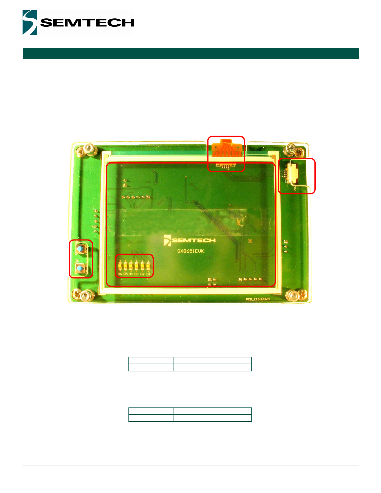
1.1. Top layer description
The evaluation board is shown on Figure 1 and each zone is described in the corresponding subsection.
Figure 1. Top of Evaluation Board
1.1.1. Connector for main touchscreen (P9)
P9 is the main touchscreen connector. It has 4 upper contacts with a pitch of 1mm. The touchscreen used on this
evaluation kit has the following reference:
1.1.2. Connector for auxiliary touchscreen (P10)
P10 is an auxiliary touchcreen connector. It has 4 upper contacts with a pitch of 1mm. An auxiliary touchscreen can be
connected as the one with the reference below:
Brand Reference
Fujitsu N010-0554-T703
Brand Reference
Bergquist 400425
1
2
34
5
Revision V1.2/March 2012
©2010 Semtech Corp.
SX8651EVK
www.semtech.com
Page 4
ADVANCED COMMUNICATIONS & SENSING
USER GUIDE
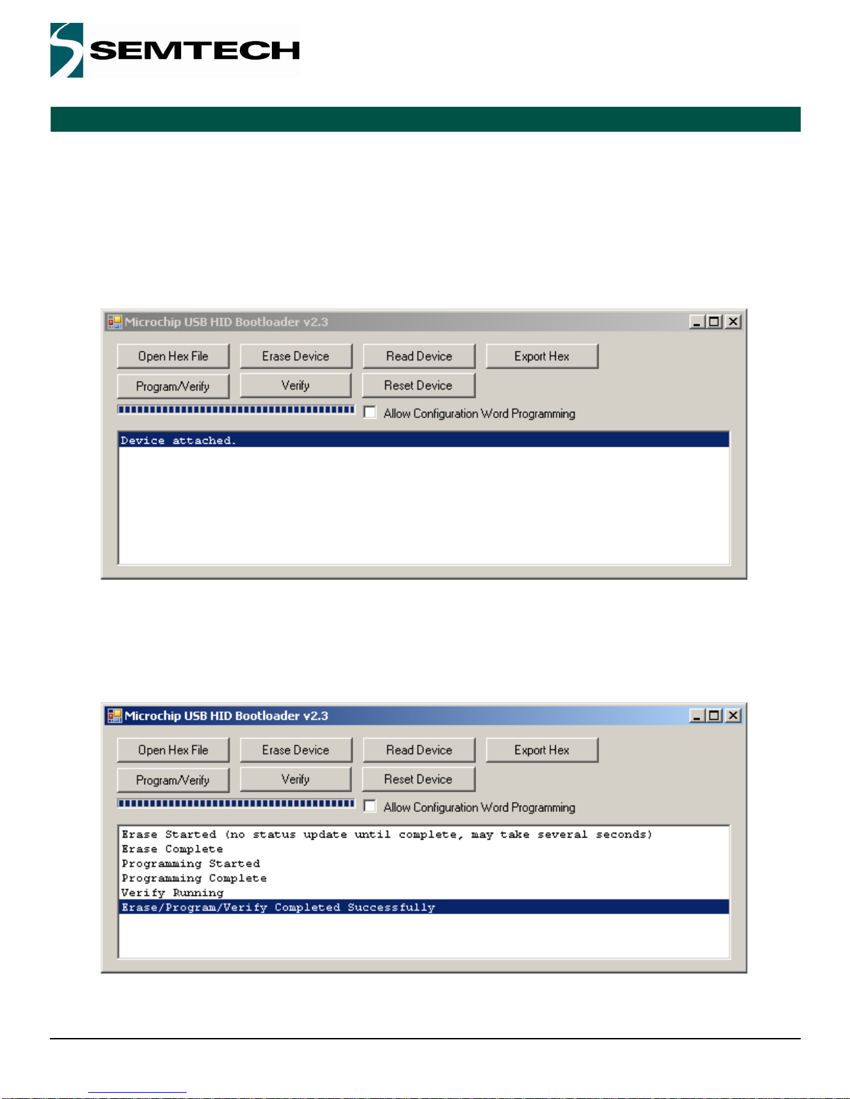
1.1.3. Switch to allows firmware update
Firmware update is a “.hex” file which can be available on Semtech web site. To update the firmware, follow the steps:
i) With the USB cable disconnected, press S2 switch
ii) Connect the evaluation board to the computer through USB while holding S2 low.
iii)Release S2 switch, the LEDs D1 and D2 should toggle (if not, it is not possible to upgrade the firmware)
iv)Run the software Microchip USB HID Bootloader. If the SX8651EVK is detected, the information “Device attached.”
is displayed as shown in Figure 2.
Figure 2. Microchip S/W interface
v) Press the button “Open Hex File” on the interface and choose the file: sx8651_MTG_SX8651EVK_vxxx.hex
vi)Press the button “Program/Verify” on the interface to program the board.
vii)The Microchip software displays “Erase/Program/Verify Completed Successfully” as in Figure 3 when the operation
is finished
Figure 3. Programming successful
Revision V1.2/March 2012
©2010 Semtech Corp.
SX8651EVK
www.semtech.com
Page 5
ADVANCED COMMUNICATIONS & SENSING
USER GUIDE
viii)Now launch SX8651Evaluation GUI
1.1.4. Controls DEL
The controls LEDs allows the user to check the operation:
1.1.5. Main touchscreen
The touchscreen is the human interface to test the double touch and single touch operation of SX8651.
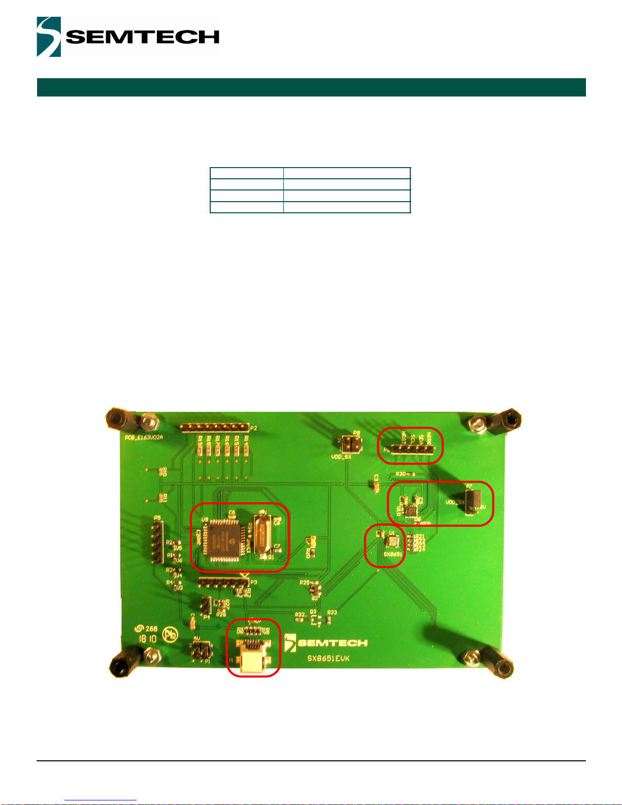
1.2. Bottom Layer Description
The electronics circuitry on the bottom layer seen on Figure 4 is needed to interface the SX8651 to the computer.
The USB connector 1is connected to the host computer. The Microchip controller 2 is used as a gateway to generate I2C
signals. The NCN4555 3 makes the level shifting and also supply the SX8651. According to the jumper P7, a supply
voltage of 3V or 1.8V can be used for the SX8651 4. The connector 5 allows the user to connect a scope and observe the
I2C communication and the controls signals NIRQ and NRST.
Figure 4. Bottom of evaluation board
LED Operation
D7 Power on
D1 Single touch
D2 Double touch
1
3
4
2
5
Revision V1.2/March 2012
©2010 Semtech Corp.
SX8651EVK
www.semtech.com
Page 6
ADVANCED COMMUNICATIONS & SENSING
USER GUIDE
2. Getting started
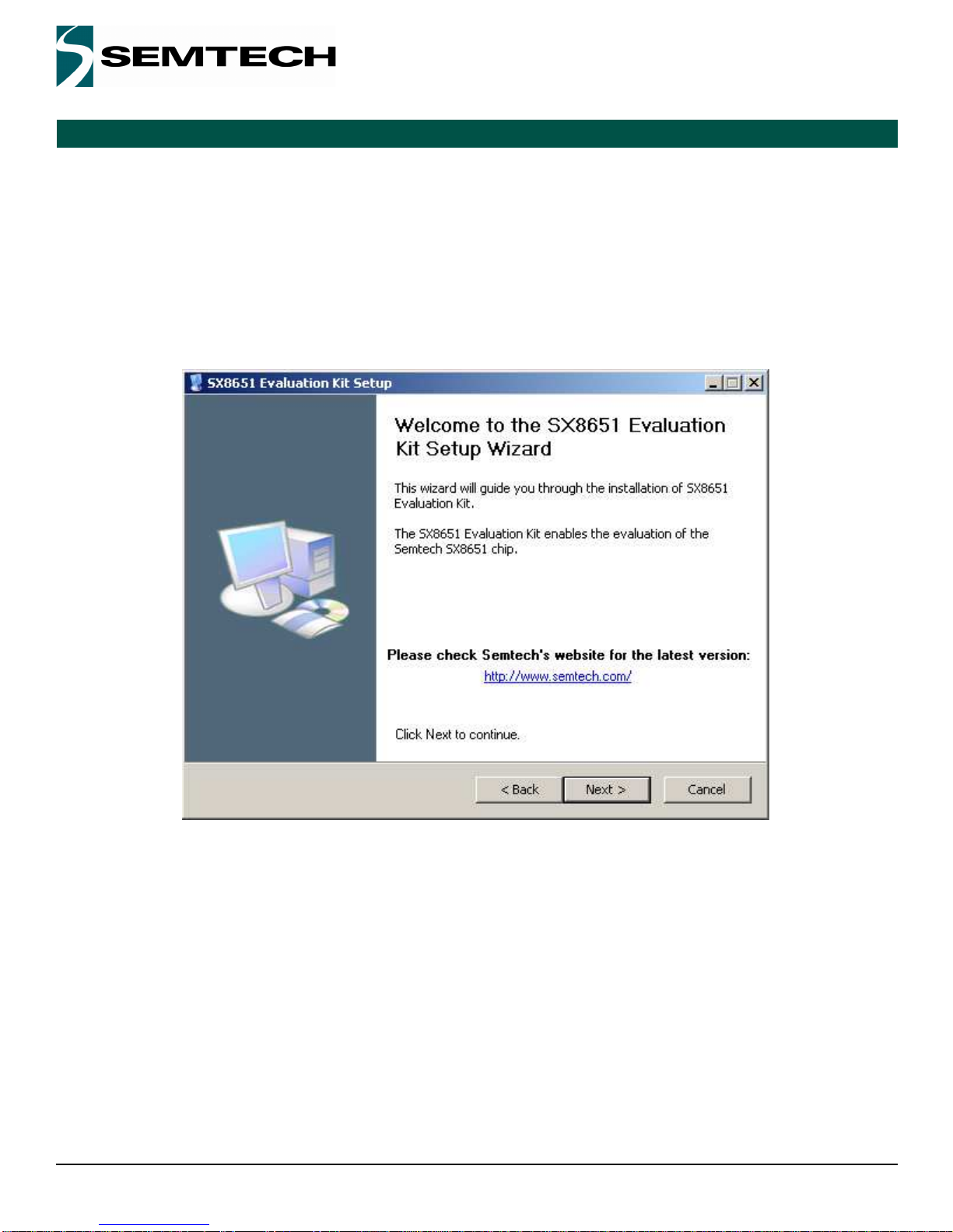
2.1. Software installation
If an internet connection is available, check the Semtech web site to download the latest version.
Otherwise, insert the CD into the CD-ROM drive of your computer. The installation should start automatically. If the
installation does not start launch the file “SX8651EvaluationKit Setup vx.x.exe“located at your CD ROM root directory.
This executable includes the Microsoft .NET Framework 2.0 which is installed if it is not detected on your system.
After selection of the installation directory, the GUI will launch.
Figure 5. Installation of the GUI
2.2. Connecting the board for the first time
Connect the board to your USB port.
The USB drivers needed by the Microchip - USB to I2C converter are installed at the first kit connection to the USB port.
Wait until the drivers installations are finished.
2.3. Running the GUI
The GUI can be launch from Windows “Start Menu->Programs->Semtech->SX8651Evaluation->SX8651”.
The GUI automatically detects the board. If not, you may have to click the “Connect” button.

Revision V1.2/March 2012
©2010 Semtech Corp.
SX8651EVK
www.semtech.com
Page 7
ADVANCED COMMUNICATIONS & SENSING
USER GUIDE
3. GUI overview
The Graphical User Interface can be used to evaluate esaily the SX8651. The subsections below describes the various
demonstrations available.
3.1. Main menu
Figure 6. Main menu
When the GUI first starts up, the Main Menu will show up. The GUI bottom left area describes if the board is connected or
not. The bottom right indicates the version number.
The three buttons in In the middle, are the available demonstrations.

Revision V1.2/March 2012
©2010 Semtech Corp.
SX8651EVK
www.semtech.com
Page 8
ADVANCED COMMUNICATIONS & SENSING
USER GUIDE
3.2. Configuration
Configuration is performed by pressing the Configuration button.
If the drawing on the GUI need to be flip or rotated, the user can adjust the screen layout by using the “Readjust Screen
Layout” button.
The gesture reporting allows the user to configure the gesture used: zoom, rotation, panning. All of them can be selected at
the same time. By default, rotation has been disabled.
3.3. Supported gesture
3.3.1. Zoom
Pinch and stretch with the finger and thumb on the touchscreen to zoom in and out a picture. It works also with two fingers
from both hands can also be used.
Figure 7. Stretch on the touchscreen to zoom in
3.3.2. Rotate
Picture rotation is done with one finger being fixed on the touchscreen and an other doing the rotation around as described
in Figure 8.

Revision V1.2/March 2012
©2010 Semtech Corp.
SX8651EVK
www.semtech.com
Page 9
ADVANCED COMMUNICATIONS & SENSING
USER GUIDE
Figure 8. Rotate
3.3.3. Panning
This option can be enabled in the configuration windows when multiples pictures are available.
Only one picture is displayed but user can add pictures by copying JPG files in the installation directory.
If pictures are added in the installation folder and the corresponding option is selected in the configuration option it is
possible to pan through the pictures with one finger going from the left to the right or vice-versa.
Figure 9. Panning
3.4. Drawing pad
The drawing pad demonstrates single touch operations on the device. The clear button (upper left) will clear out any
drawings that were done. The EVK touchscreen allows the user to hand-draw images with the stylus, the finger or any
sharp object.

Revision V1.2/March 2012
©2010 Semtech Corp.
SX8651EVK
www.semtech.com
Page 10
ADVANCED COMMUNICATIONS & SENSING
USER GUIDE
Figure 10. Drawing pad

Revision V1.2/March 2012
©2010 Semtech Corp.
SX8651EVK
www.semtech.com
Page 11
ADVANCED COMMUNICATIONS & SENSING
USER GUIDE
3.5. Picture Edit
Figure 11. Picture Edit
Picture Edit is the drawing pad with a picture in the background to demonstrate multi touch operation. Single touch
operations will draw on the screen. If the user performs a zoom operation, the picture along with the drawing will be
zoomed in/out. The configuration, discussed later, allows disabling the zoom feature.
NOTE: Rotation does not occur in Picture Edit regardless of the setting.
3.6. Picture View
The Picture View is the more advanced demonstration. This allows zoom and rotation multi-touch gestures along with
single touch panning when the picture is zoomed in. Similar to Picture Edit, zoom and rotate can be disabled through the
Configuration button (upper left).

Revision V1.2/March 2012
©2010 Semtech Corp.
SX8651EVK
www.semtech.com
Page 12
ADVANCED COMMUNICATIONS & SENSING
USER GUIDE
Figure 12. Picture View when a zoom is done
4. Troubleshooting
4.1. The SX8651EVK is disconnected
If the GUI shows that the SX8651EVK is disconnected, check the following points:
The USB cable connect the board to the computer
The diode D7 is lighted
Click the Connect button
Try an other USB port and restart the GUI
4.2. The touchscreen doesn’t work
If the SX8651EVK is connected but the touchscreen seems not to work, check the following points:
The touchscreen is well connected to the connector P9
When a finger press the screen, the LED D1 is lighted
When two fingers press the screen, the LED D1 and D2 are lighted
Restart the GUI and reconnect the board

Revision V1.2/March 2012
©2010 Semtech Corp.
SX8651EVK
www.semtech.com
Page 13
ADVANCED COMMUNICATIONS & SENSING
USER GUIDE
5. Appendix:
5.1. EVK schematics p1/2
Revision V1.2/March 2012
©2010 Semtech Corp.
SX8651EVK
www.semtech.com
Page 14
ADVANCED COMMUNICATIONS & SENSING
USER GUIDE
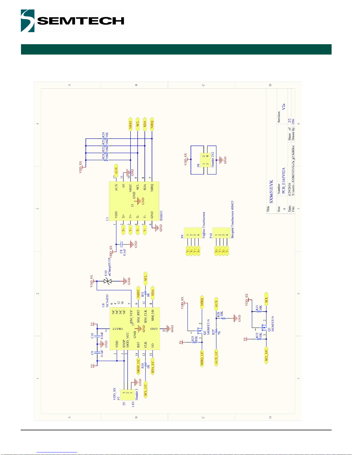
5.2. EVK schematics p2/2

Revision V1.2/March 2012
©2010 Semtech Corp.
SX8651EVK
www.semtech.com
Page 15
ISO9001
CERTIFIED
ADVANCED COMMUNICATIONS & SENSING
USER GUIDE
© Sem tech 2010
All rights reserved. Reproduction in whole or in part is prohibited without the prior written consent of the copyright owner. The
inform ation presented in this docum ent does not form part of any quotation or contract, is believed to be accurate and reliable
and m ay be changed without notice. No liability will be accepted by the publisher for any consequence of its use. P ublication
thereof does not convey nor im ply any license under patent or other industrial or intellectual property rights. Sem tech assum es
no responsibility or liability whatsoever for any failure or unexpected operation resulting from m isuse, neglect im proper
installation, repair or im proper handling or unusual physical or electrical stress including, but not lim ited to, exposure to
param eters beyond the specified m axim um ratings or operation outside the specified range.
S EM TE C H P R O D UC T S A RE NO T D ES IG N E D, IN TE N DE D , A U TH O R IZE D O R W AR R AN TE D TO B E S U ITA B LE FO R U SE IN
LIFE-SU PPOR T APPLICA TIO NS , D EVICE S OR SYS TE M S OR O THER C RITICAL APP LICATION S. INCLU SION O F
S EM TE C H P R O D UC T S IN S U C H A P PLIC AT IO N S IS U N D ER S TO O D T O B E U N D E R TA K EN S O LE LY A T T HE C U STO M E R’S
OW N R ISK. Should a custom er purchase or use S em tech products for any such unauthorized application, the custom er shall
indem nify and hold Sem tech and its officers, em ployees, subsidiaries, affiliates, and distributors harm less against all claim s,
costs dam ages and attorney fees w hich could arise.
All reference d brands, product nam es, service na m es and tra de m arks are the prope rty of t
heir respective owners.
Semtech Corporation Advanced Communications & Sensing Products
Contact information
USA 200 Flynn Road, Camarillo, CA 93012-8790.
Tel: +1 805 498 2111 Fax: +1 805 498 3804
FAR EAST 12F, No. 89 Sec. 5, Nanking E. Road, Taipei, 105, TWN, R.O.C.
Tel: +886 2 2748 3380 Fax: +886 2 2748 3390
EUROPE Semtech Ltd., Units 2 & 3, Park Court, Premier Way, Abbey Park Industrial Estate, Romsey, Hampshire, SO51 9DN.
Tel: +44 (0)1794 527 600 Fax: +44 (0)1794 527 601

Mouser Electronics
Authorized Distributor
Click to View Pricing, Inventory, Delivery & Lifecycle Information:
Semtech:
SX8651EVKA
Table of contents
Other Semtech Motherboard manuals

Semtech
Semtech EB-GS2971 User manual

Semtech
Semtech SX8650 User manual

Semtech
Semtech TSWITX-12V-EVM User manual

Semtech
Semtech Lora Mote User manual

Semtech
Semtech SX8634 User manual

Semtech
Semtech SC202A EVB User manual

Semtech
Semtech SC120 User manual

Semtech
Semtech SX1211SK915 User manual

Semtech
Semtech EB-GS3471-00 User manual

Semtech
Semtech GS3440 User manual


