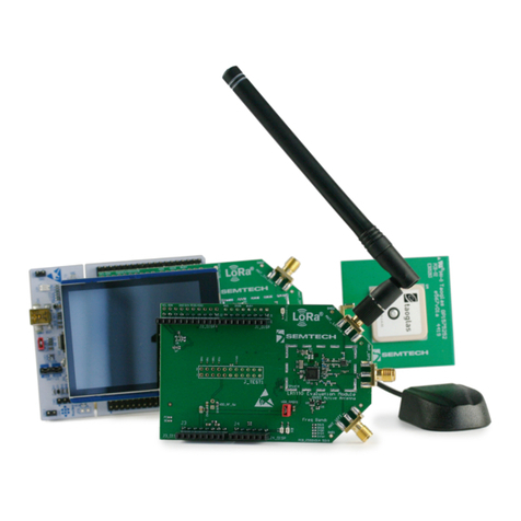
Semtech Lora Mote User manual

LoRaMoteConfig
User Guide Rev 1.2
UG001_SXC_V1.2 December 2016
2 of 15
Semtech
www.semtech.com
Revision History
Version Date Changes and/or Modifications
Rev 1.2 December 2016 Update with the Mote II requirements
Rev 1.1 Novmber 2015 Modifications to reflect Release 1.1 of the utility
Rev 1.0 July 2015 New document

LoRaMoteConfig
User Guide Rev 1.2
UG001_SXC_V1.2 December 2016
3 of 15
Semtech
www.semtech.com
Contents
Revision History ................................................................................................................................................................................................................................. 2
1. Scope................................................................................................................................................................................................................................................. 4
2. Installation....................................................................................................................................................................................................................................... 5
2.1 Prerequisite ........................................................................................................................................................................................................................ 5
2.2 Step 1: Install LoRaMoteConfig .................................................................................................................................................................................. 6
2.3 Step 2: Install STM VCP Drivers ................................................................................................................................................................................... 6
2.4 Step 3: Upgrade the Firmware .................................................................................................................................................................................... 7
2.4.1 LoraMote Firmware Upgrade.......................................................................................................................................................................... 7
2.4.2 Mote II Firmware Upgrade ............................................................................................................................................................................... 8
2.5 Step 4: Connect to the Utility ...................................................................................................................................................................................... 8
3. LoRaMoteConfig Functionality................................................................................................................................................................................................ 9
3.1 Saving and Restoring Parameters ............................................................................................................................................................................. 9
3.2 Activation Tab ................................................................................................................................................................................................................... 9
3.3 MAC Layer Tab ................................................................................................................................................................................................................10
3.4 Channel Tab .....................................................................................................................................................................................................................11
3.5 Application Tab ..............................................................................................................................................................................................................12
3.5.1 Sensors GPS Demo............................................................................................................................................................................................12
3.5.2 GPS Tracking Demo..........................................................................................................................................................................................13
3.5.3 Radio Coverage Tester.....................................................................................................................................................................................13
3.5.4 Compliance Test ................................................................................................................................................................................................14
LoRaMoteConfig
User Guide Rev 1.2
UG001_SXC_V1.2 December 2016
4 of 15
Semtech
www.semtech.com
1. Scope
The goal of this document is to describe the use of the PC utility named “LoRaMoteConfig”.
Figure 1-1: LoRaMote Config Welcome Screen
LoRaMoteConfig is useful to control PHY, MAC and application-related parameters of the firmware running in the
LoRaMote. Examples:
•Change channels
•Change activation method (personalization or activation over the air)
•Change the application, for instance a GPS tracker demo or a coverage test demo

LoRaMoteConfig
User Guide Rev 1.2
UG001_SXC_V1.2 December 2016
5 of 15
Semtech
www.semtech.com
2. Installation
2.1 Prerequisite
Please download the latest LoRaMoteConfig installer file from the Semtech web repository.
The requirements are:
•a Personal Computer running Windows 7 (tested), Windows 8 (untested) or Windows 10 (untested)
•ST Microelectronics Virtual Com Port (VCP)
•DfuSe drivers for bootloader mode, this is only needed for the LoRa Mote
•Microsoft .NET Framework 4.5 installation is automated and described below.
As far as hardware is concerned, Semtech’s (or IMST’s) LoRaMote and Mote II are supported:
Figure 2-1: LoRaMote
Figure 2-2: Mote II

LoRaMoteConfig
User Guide Rev 1.2
UG001_SXC_V1.2 December 2016
6 of 15
Semtech
www.semtech.com
2.2 Step 1: Install LoRaMoteConfig
Double click the installer “LoRaMoteConfigSetup.exe” and follow the on-screen instructions. The .NET Framework will be
installed automatically if not already present on the machine. The required material is available in the installation directory:
Figure 2-3: Installation Directory
2.3 Step 2: Install STM VCP Drivers
In order to establish connection between the LoRaMote and LoRaMoteConfig, a serial communication must be established.
Simply navigate to“/vcp” in the installation sub-folder, and launch “VCP_V1.4.0_Setup.exe”
Figure 2-4: VCP Installation

LoRaMoteConfig
User Guide Rev 1.2
UG001_SXC_V1.2 December 2016
7 of 15
Semtech
www.semtech.com
2.4 Step 3: Upgrade the Firmware
2.4.1 LoraMote Firmware Upgrade
2.4.1.1 Install the DfuSe 3.0.5 Utility in the LoRaMote
•This utility is required to re-flash the LoRaMote without the use of a JTAG programmer. Simply navigate to the /dfuse
subdirectory, double-click “DfuSe_Demo_V3.0.5_Setup.exe” and follow the on-screen instructions.
•Launch “DfuSeDemo.exe”
•The device will appear in the “Available DFU and compatible HID Devices” drop-down list, select it
•Select both offered options, as below:
Figure 2-5: DfuSe Programming Options
•With the “Choose” button, navigate to the “mote-bin” sub-folder and select the binary file,
“LoRaMoteConfig-eu868.dfu”
Figure 2-6: Firmware DFU File Location
•A warning message will be displayed when the “Upgrade” button is hit, select ”OK”
The firmware of the LoRaMote is now up-to-date, and compatible with the installed version of LoRaMoteConfig PC utility.

LoRaMoteConfig
User Guide Rev 1.2
UG001_SXC_V1.2 December 2016
8 of 15
Semtech
www.semtech.com
2.4.1.2 Upgrade the Firmware in the LoRaMote
The LoRaMote needs to be set in bootloader mode:
•Remove its USB cable (or turn it off with the slide switch, ensuring there is no battery inside)
•Pinch the PCB-etched RF antenna
Figure 2-7: Press the Antenna to Enter Bootloader Mode
•Power-up the mote by connecting back the USB cable
•Observe the three LEDs flashing at a one second interval which indicate the platform is now in bootloader mode. If the
three LEDs are not flashing, then the process must be done again as there was an issue with the detection of the finger
on the sensor antenna
Note: if the LEDs do not flash, it is certainly because the Bootlader is not installed on the device. A binary file
“Bootloader.hex”, provided in the same directory, should be flashed onto the device. To this end, the enclosure should be
opened, and a JTAG programmer such as ST’s STLink can be used
2.4.2 Mote II Firmware Upgrade
•Select the file "MoteIIConfig-eu868.bin", copy and paste it into the disk created “Mote_II"
•The LED will blink red and green alternatively, and when the upgrade is finished it will stay green
•Press the reset button
•The unit will display "Mote II"
2.5 Step 4: Connect to the Utility
The LoRaMote shall now be connected to the PC, and a Virtual Com Port will be assigned when the driver is installed.
Note: the COM port number can be looked-up from Windows Device Manager
From the Windows start menu, launch LoRaMoteConfig.exe, and select the appropriate COM port number from the List:
Figure 2-8: Connect the LoRaMote to LoRaMoteConfig
Once this is done, hit the blue button, and the node is now connected to the application.

LoRaMoteConfig
User Guide Rev 1.2
UG001_SXC_V1.2 December 2016
9 of 15
Semtech
www.semtech.com
3. LoRaMoteConfig Functionality
Most parameters related to the implementation of a sensor connected to a LPWAN network following the LoRaWAN R1.0
specification, can be modified by the PC application for later use in a stand-alone fashion. They are stored in the E2PROM
of the host microcontroller.
3.1 Saving and Restoring Parameters
Figure 3-1: Control buttons
•Write: Writes the current configuration to the EEPROM
•Read: Reads the current configuration from the EEPROM
•Defaults: Resets the configuration to its default values
•Reset: Resets the LoRaMote. The new configuration is only applied once the LoRaMote has been reset.
3.2 Activation Tab
Figure 3-2: Activation Tab
Activation method (OTAA or Personalization) can be selected here. Depending on the chosen method, parameters can be
modified:
•OTAA: AppEUI and AppKey. An automatically-calculated AppKey is proposed to simplify the process, and will be
unique to each DevEUI
•Personalization: AppSKey and NwkSKey can be programmed here

LoRaMoteConfig
User Guide Rev 1.2
UG001_SXC_V1.2 December 2016
10 of 15
Semtech
www.semtech.com
3.3 MAC Layer Tab
Figure 3-3: MAC Layer Tab
All parameters related to the MAC Layer are controlled here. Remarks:
•ADR should be turned off for the testing of mobile sensors
•Transmission redundancy indicates how many times the same unconfirmed packet should be repeated (same FCnt)
•EU868 PHY Duty Cycle enforcement can be temporarily turned off, in instances where a large number of packets must
be send over a short period of time
•Network Type selects the type of SyncWord used for the LoRa packets, i.e. 0x12 for “Private Networks” and 0x34 for
“Public networks”

LoRaMoteConfig
User Guide Rev 1.2
UG001_SXC_V1.2 December 2016
11 of 15
Semtech
www.semtech.com
3.4 Channel Tab
Up to 16 channels can be defined, edited, enabled or disabled. The “Load” and “Save” buttons can be used to save and
duplicate a channel line-up into multiple LoRaMotes. The channel definition is stored in an JSON ASCII file which can be
easily transported and edited with any text editor.
Figure 3-4: Channel Tab

LoRaMoteConfig
User Guide Rev 1.2
UG001_SXC_V1.2 December 2016
12 of 15
Semtech
www.semtech.com
3.5 Application Tab
Four applications are currently implemented:
•Sensor GPS demo: the Mote reports back, at pre-defined intervals, information from the set of sensors, along with its
GPS coordinates
•GPS Tracking demo is a slight variation, where the FRMPayload size is reduced by removing most of the sensor
information, except compressed GPS coordinates
•Radio Coverage Tester allows to systematically test Packet Success Rate over a pre-defined number of packets
•Compliance Test incorporate a basic “Echo” application which can be used to test the protocol (Semtech tool)
3.5.1 Sensors GPS Demo
When this application is selected the LoRaMote sends the frames to port 2 and they are formatted as follows:
Figure 3-5: Sensors GPS Demo Frame
Table 3-1: Frame fields description
Frame field Conversion Variable type
LED 0: OFF
1: ON unsigned 8 bits
Pressure hPa/10 unsigned 16 bits
Temperature °C * 100 signed 16 bits
Altitude (Barometric) m * 10 signed 16 bits
Battery
0 The end-device is connected to an external power source.
1..254 The battery level, 1 being at minimum and 254 being at maximum
255 The end-device was not able to measure the battery level
unsigned 8 bits
GPS
Latitude & Longitude
The GPS latitude and longitude fields encode the geographical location as
follows:
•The north-south latitude is encoded using a signed 24 bit word
where -223 corresponds to 90° south (the South Pole) and 223
corresponds to 90° north (the North Pole). The equator
corresponds to 0.
•The east-west longitude is encoded using a signed 24 bit word
where -223 corresponds to 180° west and 223 corresponds to
180° east. The Greenwich meridian corresponds to 0.
signed 32 bits
GPS
Altitude meters signed 16 bits

LoRaMoteConfig
User Guide Rev 1.2
UG001_SXC_V1.2 December 2016
13 of 15
Semtech
www.semtech.com
3.5.2 GPS Tracking Demo
When this application is selected the LoRaMote sends the frames to port 4 and they are formatted as follows:
Figure 3-6: GPS Tracking Demo Frame
3.5.3 Radio Coverage Tester
This application enables the Packet Error Rate measurement on all available channels at 3 different data rates for each of
the selected site. All participating gateways log every incoming packets into a CSV file which can be later analysed by
Semtech in order to generate the report.
Note: This test doesn’t rely on GPS
The LoRaMote sends the frames to port 15 and they are formatted as follows:
Figure 3-7: Radio Coverage Tester Frame
Table 3-2: Frame fields description
Before doing the tests one must define the test sites. From experience each test site takes in average 10 minutes. So, do not
plan more than 30 sites for a day else it becomes unmanageable.
Test procedure:
•Go to first site
•Set the “ID” field to 0 and “Number of packets” field to 15
•Reset the LoRaMote
•The end device led starts to blink fast at first then slower, each blink corresponds to one frame transmitted
•Take a picture of the site and write down in the log book the site position and characteristics. This is compulsory to be
able to repeat accurately the test later on at exactly the same location and also to generate the report.
Frame field Conversion Variable type
ID Represents the test site identification unsigned 8 bits
RxRssi
Uplink only always 0
Downlink activated represents the received RSSI in dBm signed 16 bits
RxSnr Uplink only always 0
Downlink activated represents the received SNR in dB signed 16 bits
DownlinkCounter Uplink only always 0
Value incremented each time a downlink happens unsigned 16 bits

LoRaMoteConfig
User Guide Rev 1.2
UG001_SXC_V1.2 December 2016
14 of 15
Semtech
www.semtech.com
•When the LED stops blinking the test is over.
•Go to second site and set the “ID” field to 0
Note: Changing the “ID” field number with each site is capital. It enables the script later on to separate which data comes
from which site.
•Repeat the procedure as much as necessary to cover all selected sites.
•At the end of the test, log onto each gateway and recover all the packet-logger files. All those files can be placed in the
same directory on the PC. There might be several log files because the packet-logger closes the log file every 30
minutes and opens a new one each time to avoid losing all data in case of crash.
•Zip the log directory and send it to support_r[email protected] for report generation.
3.5.4 Compliance Test
The compliance tests are part of the Sensors GPS Demo and GPS Traking Demo applications. These can be accessed using
the port 224 as specified by the LoRaAlliance.

Important Notice
Information relating to this product and the application or design described herein is believed to be reliable, however such information
is provided as a guide only and Semtech assumes no liability for any errors in this document, or for the application or design described
herein. Semtech reserves the right to make changes to the product or this document at any time without notice. Buyers should obtain the
latest relevant information before placing orders and should verify that such information is current and complete. Semtech warrants
performance of its products to the specifications applicable at the time of sale, and all sales are made in accordance with Semtech’s
standard terms and conditions of sale.
SEMTECH PRODUCTS ARE NOT DESIGNED, INTENDED, AUTHORIZED OR WARRANTED TO BE SUITABLE FOR USE IN LIFE-SUPPORT
APPLICATIONS, DEVICES OR SYSTEMS, OR IN NUCLEAR APPLICATIONS IN WHICH THE FAILURE COULD BE REASONABLY EXPECTED TO
RESULT IN PERSONAL INJURY, LOSS OF LIFE OR SEVERE PROPERTY OR ENVIRONMENTAL DAMAGE. INCLUSION OF SEMTECH PRODUCTS IN
SUCH APPLICATIONS IS UNDERSTOOD TO BE UNDERTAKEN SOLELY AT THE CUSTOMER’S OWN RISK. Should a customer purchase or use
Semtech products for any such unauthorized application, the customer shall indemnify and hold Semtech and its officers, employees,
subsidiaries, affiliates, and distributors harmless against all claims, costs damages and attorney fees which could arise.
The Semtech name and logo are registered trademarks of the Semtech Corporation. All other trademarks and trade names mentioned
may be marks and names of Semtech or their respective companies. Semtech reserves the right to make changes to, or discontinue any
products described in this document without further notice. Semtech makes no warranty, representation or guarantee, express or
implied, regarding the suitability of its products for any particular purpose. All rights reserved.
© Semtech 2016
LoRaMoteConfig
User Guide Rev 1.2
UG001_SXC_V1.2 December 2016
16 of 16
Semtech
16
Contact Information
Semtech Corporation
Wireless & Sensing Products
200 Flynn Road, Camarillo, CA 93012
Phone: (805) 498-2111, Fax: (805) 498-3804
www.semtech.com
This manual suits for next models
1
Table of contents
Other Semtech Motherboard manuals

Semtech
Semtech LoRa Edge Tracker Reference Design Evaluation... User manual

Semtech
Semtech SX1211SK915 User manual

Semtech
Semtech TSWITX-12V-EVM User manual

Semtech
Semtech LoRa Edge LR1110 User manual

Semtech
Semtech SC21150 User manual

Semtech
Semtech EB-GS3471-00 User manual

Semtech
Semtech SX8651EVK User manual

Semtech
Semtech EB-GS2971 User manual

Semtech
Semtech SX9306 User manual

Semtech
Semtech SC202A EVB User manual