Seneca S203TA User manual

Technical Specifications
Input
S203TA Advanced Three-phase Network Analyzer
GeneralDescription
ModelS203TAisacompletethree-phasenetworkanalyzersuitedfor use with up to
600Vac voltage range, and current range given by the nominal range of the CTs with 5A
Outputconnected.
The instrument provides all the following electrical measurable quantities: Vrms, Irms,
Watt, Var, Va, Frequency, Cos Active Energyand . All measurements given above
(exceptfrequency)areavailablebothsingle-phaseandthree-phase.
Measurements are read through serial communication both in floating point and
normalisedformat(exceptFrequencyandActiveEnergy).
The DIP-switches can be set for the analog retransmission of any Vrms, Irms, Watt and
Cos quantity either single phase or three-phase, or any phase chosen (by specific
MODBUSregistry).Themoduleisalsodistinguishedby:
CommunicationconfigurabilitythroughDIP-switchorsoftware.
RS485serialcommunicationwithMODBUS-RTUprotocol,maximum32nodes.
Easy-wiringofpowersupplyandserialbusbymeansofthebushousedintheDINrail.
Highprecision:0,2%class.
ProtectionagainstESDdischargeupto4kV.
Powerinputinsulation:3750Vactowardsalltheothercircuits.
Insulationbetweencommunicationandpowersupply:1500Vac.
Insulationbetweenretransmittedoutputandpowersupply:1500Vac.
Analogoutputsignalsettableinvoltageorcurrent.
PossibilityforconnectionandmanagementbyexternalCTswith5Aoutput.
Allkindofinsertionpossible:singlephase,threeorfourwires(three-phasewith3 CTs).
Possibility to compensate errors caused by frequency change in places where network
frequencyisnotstable(frequencychanges>30mHz).
Power Supply :
Consumption :
Communication Ports:
Protocol :
10 - 40 Vdc o 19 - 28 Vac (50 - 60 Hz).
max 2,5 W.
Rs485,1200-115200Baud.
MODBUS-RTU.
MI001458-E ENGLISH - 1/16
Voltage Input Upto600Vac,Frequency:50o60Hz.
Ratedrange:givenbyI ofCT.NOMINAL
MaxCrestFactor:3.
MaximumCurrent:3*I ofCT.NOMINAL
Current Input :
Class/Base Precision :
(1)
NetworkFrequency:50or60Hz.
Voltmeter:0,2%.
Amperometer:0,2%.
Wattmeter:0,2%.
Max Resistance of each CT’s
secondary wire : Thesumoftheresistanceofthewiregoing(fromCTto
load)andback(fromloadtoCT)<ratedburden
Vrms: 40..600 Vac
: 0,4-100% Iprimary of TAIrms
(1): Precisions are given in the following range:
EN

MI001458-E ENGLISH - 2/16
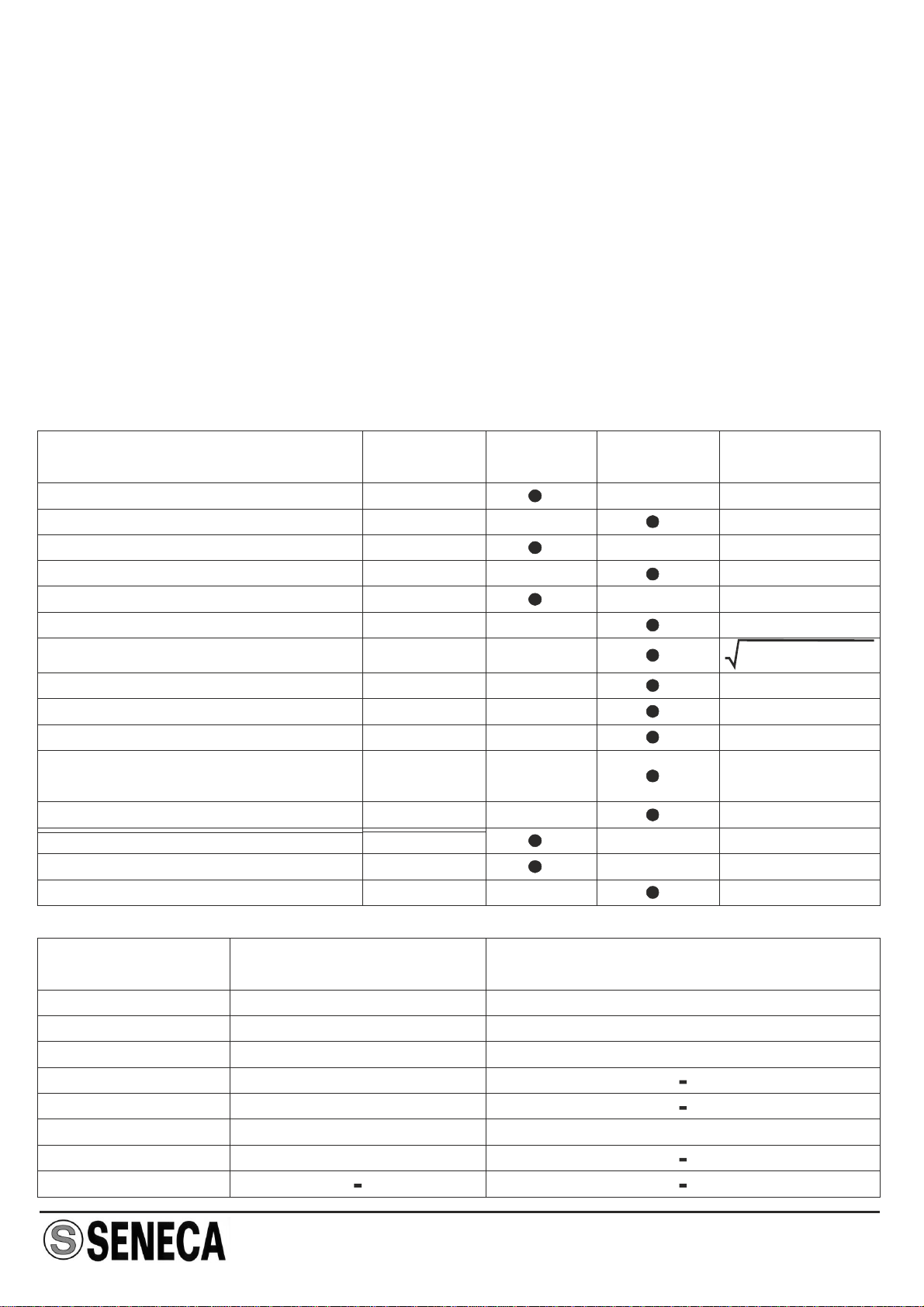
Insulation voltage :
International protection :
Environmental conditions :
Storage temperature :
Signalling by LED :
Connections :
Reference standards :
3750 Vac between the measurement input and all the
othercircuits.
1500 Vac between power supply and communication.
1500 Vac between power supply and analog output.
IP20.
Temperature -10-+65°C.
Humidity 30 - 90 % non-condensing.
Altitude 2000 slm.
-20 - +85 °C.
Power supply, Fail, RS485 communication.
Removable 3-way screw terminals, 5.08 mm pitch.
EN61000-6-4/2002-10 (electromagnetic emission,
industrialenvironment).
EN61000-6-2/2006-10 (electromagnetic immunity,
industrialenvironment).
EN61010-1/2001(safety)
All circuits must be insulated from the other circuits
under dangerous voltage with double insulation. The
power supply transformer mustcomplywith EN60742:
“Insulatedtransformersandsafetytransformers”.
Plastic UL 94 VO, grey color.
Other Specifications
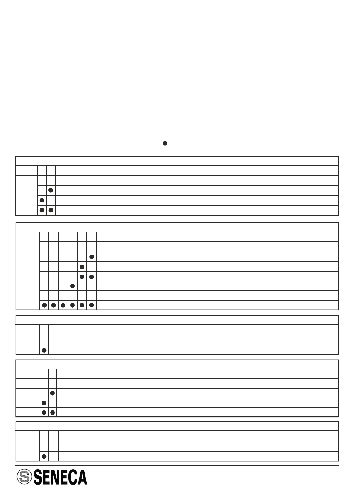
Operatinglogic
The module measures the following electrical quantities: Vrms, Irms, Watt, Var, Va,
Frequenza, Cos and Active Energy, and provides the values in the corresponding
MODBUSregisters.
In three-phase environments, measurements given above corresponding to any phase
areavailable,otherthanthethree-phasevalue(exceptthefrequencyofcourse).
These measurements are rendered in both floating point and normalised format (except
Frequency and Active energy) between 0 - +10000 (-10000 - +10000 for VAR e Cos ).
Active energy value is stored in memory and when the instrument is switched off, the last
valuebeforeswitchingiskeptinmemory.
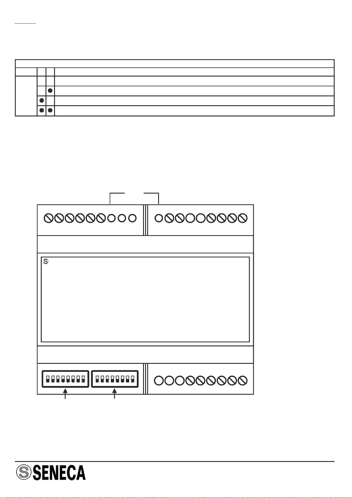
The module output can transmit, via DIP-switch setting, one of the following quantities:
Vrms,Irms,Watt,cos aseitheracurrentorvoltagevalue.Iftheinstrumentissetforthree-
phase measurements, it transmits automatically the three-phase value of the selected
measurement. However, via MODBUS register, the user can choose to transmit the
measurementcorrespondingtoanyphase:A,B,C.
The user can set through MODBUS the values and of the measurement toMIN MAX
transmitcorresponding to 0%and100% of theanalogoutput. Forexample, ifthe signalis
transmittedascurrent4..20mAandthequantitytotransmitisvoltageVrmsinthe10..300
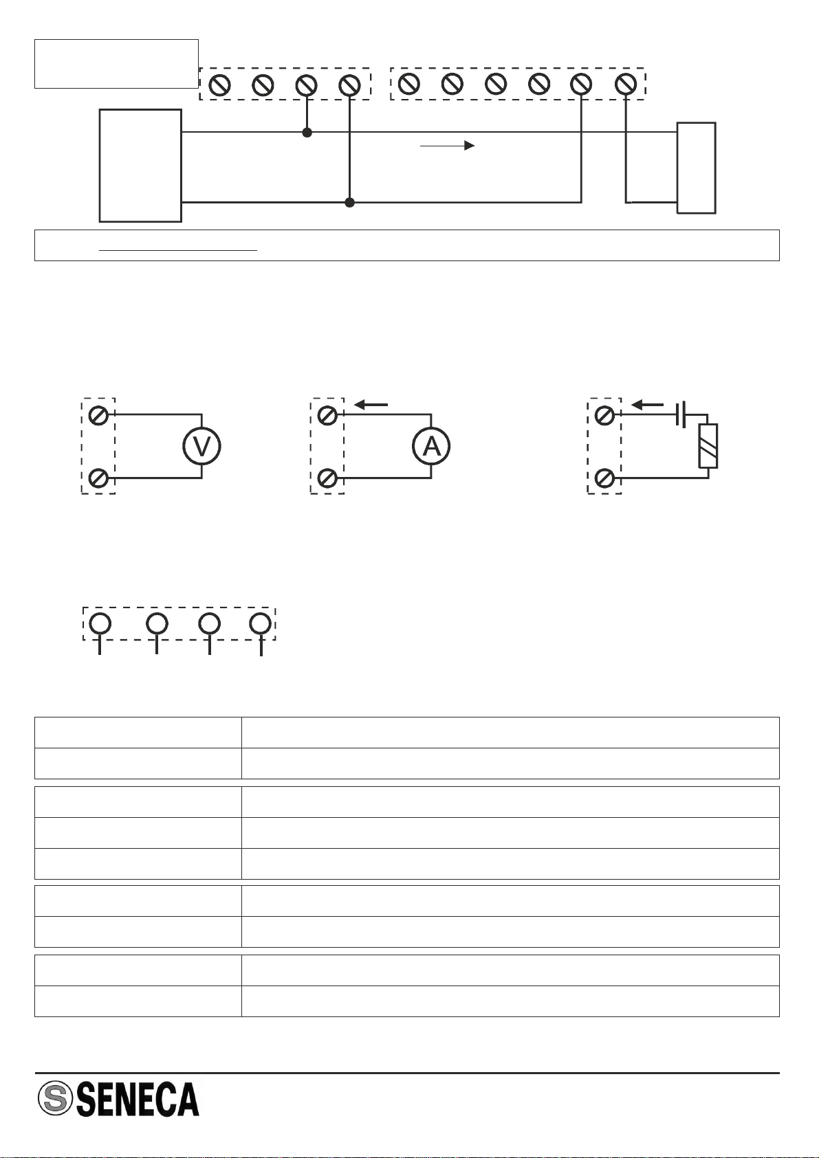
Analog Output
Voltage Output : 0-10Vdc,0-5Vdc,Min.loadresistance:2k
Current Output : 0-20mA,4-20mA,Maxloadresistance:500
Transmission error : 0,1%(maxrange).
Response time (10%..90%) : 0,4s.
Dimensions (L x W x H) : 105 x 89 x 60 mm
Box :

MI001458-E ENGLISH - 3/16
Measurement and retransmission range
V range,(therefore ), then if Vrms measured is 10V, analog output willMIN=10, MAX=300
be 4mA, while if Vrms=300V outputwill be 20mA. In the intermediate points the behaviour
is linear. The retransmission values saturate at approximately 11 V for voltage output and
at22mAforcurrentoutput(analogoutputclampedat110%).
If network frequency oscillates more than 30 mHz from rated values (50 o 60 Hz), it’s
possibile to compensate errors on measurements of Power and Energy caused by these
variations.This option is selectable via MODBUS register. Vrms and Irms measurements
arenotinfluencedbythesevariations.
When the module is switched on, the appropriate setting coefficients are measured
(depending on the choice of 50 or 60 Hz frequency). All the settings made will be
automaticallyloadedwhenthemoduleisreset.
Total three-phase active energy E E +E +EA B C
Active Energy (phase) E E EA B C
Frequency Hz
Total three-phase coscos _3PHP/S
Total three phase apparent power S S +S +SA B C
cos (phase) cos cos A B
cosCP /S
A,B,C A,B,C
Apparent power (phase) S S SA B C V *IA,B,C A,B,C
Total three phase reactive power Q Q +Q +QABC
Reactive power (phase) Q Q QA B C
Total three phase active power P P +P +PA B C
Mean three phase current I (I +I +I )/3A B C
Active power (phase) P P PA B C
Root-mean squared current I I IABC
Mean three phase voltage V (V +V +V )/3A B C
Root-mean squared voltage V V VA B C
Electrical
Quantity Symbols
used Measured
Values Calculated
Values Equation
used
Electrical Measurements
(S ) -(P )
A,B,C A,B,C
2 2
Electrical
Quantity Measurement
Range Selectable retransmission
Range
Vrms
Irms
Active Power
Reactive Power
Apparent Power
Frequency
Active Energy
0..600 Vac
0..I of TAPRIMARY
(0..IPRIMARY TA * 600)VAR
(0..I TA * 600)WPRIMARY
0..1
(0..I TA * 600)VAPRIMARY
40..70 Hz
0..10 V, 0..5 V, 0..20 mA o 4..20 mA
5..10 V, 2,5..5 V, 10..20 mAo 12..20 mA

MI001458-E ENGLISH - 4/16
Electric connections SERIAL PORT RS485
POWER SUPPLY
ThereisnoinsulationbetweenRS485andtheanalogoutput
25
26 10 ÷ 40 VDC
19 ÷ 28 VAC
2.5 W B
A
GND
32
31
33
VGA
N
22212019
181716151413
CT
ZL
SINGLE
PHASE
VGA
C
B
22
21
2019
181716151413
CT
CT ZL
3 WIRES
(Three-Phase
without Neutral)
VGA
C
B
22212019
181716151413
CT
NZL
CT
CT
CT
4 WIRES
(Three-Phase with
Neutral)
Note: You can’t connect the secondary of any CTs to the Earth.
Pins 14, 16 18 and 22 are internally connected.

MI001458-E ENGLISH - 5/16
Indications by LED on the frontal panel
27 28 29 30
PWRERR Tx Rx
PositionandIdentificationofLEDs
LedIndications
Voltage
+
Active Current (1)
Ext. Power Supply Current(2)
ThereisnoinsulationbetweenRS485andtheanalogoutput.
34
35
35 34
36 36
+
OUTPUT
The module provides an analog output in voltage (0..10 Vdc, 0..5 Vdc) or active and
passive current (0..20 mA, 4..20 mA). We recommend using shielded cables for the
electricconnections.
(1) Passive Output already powered to connect to passive inputs.
(2) Passive Output not powered to connect to active inputs.
27: (GREEN)PWR LED Description
Steady On Power supply is present
28: (YLW)ERR LED Description
Steady On Communication error between internal peripherals
Blinking At least one of the active phases’ voltage is less than 40 Vac
29: (RED)TX LED Description
Steady On Data are being transmitted through the RS485 comm. port
30: (RED)RX LED Description
Steady On Data are being received through the RS485 comm. port
SINGLE PHASE
WITHOUT TA
VGA
N
22212019 18 17 16 15 14 13
ZL
5 Arms Max
Note: to the different pins position from the other schematicsPAY ATTENTION

MI001458-E ENGLISH - 6/16
0..5 V
0..20 mA
4..20 mA
SW2 0..10 V
ANALOG OUTPUT
Fixed Address: 03
Fixed Address: 04
Fixed Address, as from binary representation
Fixed Address: 63
Fixed Address: 02
Communication Parameters from EEPROM
Fixed Address: 01
SW1 43
X
5
X
6
X
7
X
8
X X
ADDRESS
In all the following tables, the indication corresponds to a DIP-switch set in 1(ON); no
indication is provided when the DIP-switch is set in 0 (OFF).
Network frequency 60 Hz
Single-phase
1
4 5
SW2
SW2
Network frequency 50 Hz
Three-phase
NETWORK FREQUENCY SELECTION (50 o 60 Hz)
SELECTION OF ENVIRONMENT: SINGLE-PHASE OR THREE-PHASE
2 3
57600 Baud
38400 Baud
19200 Baud
9600 Baud
1SW1 2
SPEED
DIP-SWITCH SETTING
The instrument leaves the factory with all DIP-switches configured in position 0. The
setting of the DIP-switches defines the module’s communication parameters: address
and speed and the following settings
The isthefollowing:DefaultConfiguration
Baudrate:38400.
Address : 1.
Network Frequency : 50 Hz.
Analog Output : 0..10 V.
Environment : Three-phase.
Insertion type : 4 wires.
Transmitted quantity : Mean three-phase voltage.

MI001458-E ENGLISH - 7/16
Serial interface
Fordetailedinformationon RS485serialinterface,consultthedocumentationprovidedby
thewebsitewww.seneca.it,inthesection .Prodotti/SerieZ-PC/MODBUS TUTORIAL
For the product’s programming and/or configuration tools, consult the website
www.seneca.it.
During initial programming, the EEPROM (SW1 3..8 in OFF position) default setting
valuesoriginallyprogrammedasfollowscanbeused:
Address=001 SPEED=38400Baud PARITY=none, BIT NUMBER=8, STOP BIT=1., ,
Programming
Retransmission of cos
Retransmission of Watt
Retransmission of Irms
Retransmission of Vrms
Leds, Screw terminals and DIP-switch positions
SW2 6 7
SELECTION OF QUANTITY RETRANSMITTED
10 11 12
SENECA
S203TA
13 14 15 16 17 18
2736 2635 2534 2433 2332 2231 2130 2029 1928
SW1
LED
SW2
Note: The DIP-switch 5 of Sw2 must always be in the OFF position

MI001458-E ENGLISH - 8/16
MODBUS REGISTERS
Holding Registers
The 16-bit Holding Registers have the following structure:
TheBitnotation[x:y]showninthe
table indicates all the bits from x
to y. For example, Bit [2:1]
indicates bit 2 and bit 1, and
illustrates the meaning of the
various linked combinations of
the values of the two bits.
Remember that the MODBUS 3,
6and16functions(respectively
Supported MODBUS Commands
15 14 13 12 11 10 9 8 7 6 5 4 3 2 1 0
Most significant
Bit Least
Significant Bit
Index Bit
Word (16 bit): MODBUS Register
S203TAhas MODBUS 16 bits(words) registers, accessible by RS485communication. In
the next paragraphs, we shall describe the supported MODBUS commands, and the
functionsoftheregisters.
16 Write Multiple Register Writing of registers up to 16 words at a time
within the same group
06 Write Single Register Writing of a word register
03 Read Holding Registers Reading of registers up to 16 words at a time
within the same group
Code Function Description
Disposal of Electrical & Electronic Equipment (Applicable throughout the European Union and other
Europeancountrieswithseparatecollectionprograms)
Thissymbol,foundonyourproductoronitspackaging,indicatesthatthisproductshouldnotbetreatedas
household waste when you wish to dispose of it. Instead, it should be handed over to an applicable
collection point for the recycling of electrical and electronic equipment. By ensuring this product is
disposed of correctly, you will help prevent potential negative consequences to the environment and
humanhealth,whichcouldotherwisebecausedbyinappropriatedisposalofthisproduct.Therecyclingof
materialswillhelptoconservenaturalresources.Formoredetailedinformationabouttherecyclingofthis
product, please contact your local city office, waste disposal service or thè retail store where you
purchasedthisproduct.
SENECA s.r.l.
Via Austria, 26 - 35127 - PADOVA - ITALY
Tel. +39.049.8705355 - 8705359 - Fax +39.049.8706287
Thisdocumentisproperty ofSENECAsrl.Duplicationandreprodutionareforbidden,ifnotauthorized.Contentsofthe
presentdocumentationreferstoproductsandtechnologiesdescribedinit.Alltechnicaldatacontainedinthedocument
maybemodifiedwithoutpriornoticeContentofthisdocumentationissubjecttoperiodicalrevision.
ofmultiplereading,singleandmultiplewriting)canbeexecutedonthe followingregisters.
Defaultvaluesaremarkedwith*symbol.
Thefollowingindication(onlyreadableoralsowritable)isprobidedforeveryregister:
R:Readable - W:Writeable

ENGLISH - 9/16MI001458-E
REGISTER
MACHINE ID Description
Bit[15:8]containthemodule’sID:41.
Bit [7:0] contain the firmware’s external
revision
R/W
R
IND.
40001
I_PRIM_FL_MSW
CHECK_TA
PHASE_RETR
SelecttheratedcurrentofCTsinfloatingpoint
(mostsignificativeword).
Kindof CT used:passive CT or compensated
CT
Select the phase on which the analog output
willtransmit.
R/W
R/W
R/W
40018
40016
40017
Select the rated current of the CTs connected to
the instrument in floating point format. This
register influences floating point value of: Irms,
Active power, Apparent Power, Reactive Power
and Energy (both single and three-phase). It
doesn’t influence normalised values (0 - 10000)
andtransmittedoutput.Default:1000,0.
Value of the quantity to transmit (defined via DIP-
switch and phase selected via PHASE_RETR
register, 40017) which gives the minimum value
(0%) of the transmitted output. The value is
expressed in floating point format (most
significative word) and therefore it must be
expressed in the corresponding measurement
unit of the quantity chosen (V for Vrms, mA for
Irms,WforWatt).Default:0,0.
Notused.
I_PRIM_FL_LSW SelecttheratedcurrentofCTsinfloatingpoint
(leastsignificativeword). R/W40019
Bit [15:0]
Bit [15:0]
Bit [15:1]
Bit 0
Bit [15:0]
Select thekindof CT used:
0*:PassiveCTwith5Aoutput.
1:CompensatedCT,whichhasnophaseerror.
Precision class of the instrument is given by (CT
class)+0,3.
Select the phase on which the analog output
wiltransmitthequantityselected:
0:PhaseA(defaultforsingle-phase).
1:PhaseB.
2:PhaseC.
Allothervalues:Threephasevalue(defaultthree-
phase).
MINOUT_FL_MSW Value of the quantity to transmit which gives
the minimum retransmitted output (floating
pointformat,mostsignificativeword).
40020 R/W

MI001458-E ENGLISH - 10/16
Value of the quantity to transmit (defined via DIP-
switch and phase selected via PHASE_RETR
register, 40017) which gives the maximum value
(100%) of the transmitted output. The value is
expressed in floating point format (most
significative word) and therefore it must be
expressed in the corresponding measurement
unit of the quantity chosen (V for Vrms, mA for
Irms,WforWatt).Default:600,0.
Bit [15:0]
ADDR_PARITY
Bit [15:8]
Bit [7:0]
Register for the setting of the module’s
address and parity control.
Set the module’s address. Allowed values from
0x00 0xFFa (decimal values in the interval of 0-
255).Default:1.
Set the type of parity control:
00000000* : No parity ( NONE )
00000001 : Even parity ( EVEN )
00000010 : Odd parity ( ODD )
R/W40025
MAXOUT_FL_MSW Value of the quantity to transmit which gives
the maximum retransmitted output (floating
pointformat,mostsignificativeword).
40022 R/W
MINOUT_FL_LSW
MAXOUT_FL_LSW
CHECK_FREQ
Value of the quantity to transmit which gives
the minimum retransmitted output (floating
pointformat,leastsignificativeword).
Value of the quantity to transmit which gives
the maximum retransmitted output (floating
pointformat,leastsignificativeword).
Enables measurement errors compensation
of Active Power and Energy caused by
networkfrequencyvariations.
40021
40023
40024
R/W
R/W
R/W
Bit [15:1]
Bit 0 Notused
Errors compensation caused by network
frequencyvariations:
1: If networkfrequency is not stable at50 Hzor 60
Hz, or has consistent variations (> 30 mHz), this
register corrects the measurement of Power and
Energy.The measurements of Vrms and Irms are
notinfluencedbythissetting.
BAUDR_ANSDEL Register for the setting of the Baud rate and
the response delay time in characters. R/W40026
Bit [15:8] Set the serial communication speed value
(Baudrate):

MI001458-E ENGLISH - 11/16
00000000 (0x00): 4800 Baud
00000001 (0x01): 9600 Baud
00000010 (0x02): 19200 Baud
00000011*(0x03): 38400 Baud
00000100 (0x04): 57600 Baud
00000101 (0x05):115200 Baud
00000110 (0x06): 1200 Baud
00000111 (0x07): 2400 Baud
VRMS_A_FL_MSW
VRMS_B_FL_MSW
VRMS_C_FL_MSW
VRMS_A_FL_LSW
VRMS_B_FL_LSW
VRMS_C_FL_LSW
Single phase or phase A Vrms measurement
(floatingpoint,mostsignificativeword)inVolt
Phase B Vrms measurement (floating point,
mostsignificativeword)inVolt
Phase C Vrms measurement (floating point,
mostsignificativeword)inVolt
Single phase or phase A Vrms measurement
(floatingpoint,leastsignificativeword)inVolt
R
R
R
R
R
R
40135
40137
40139
40136
40138
40140
RESET_ZERO
ENERGY
STATUS
Resetinstrumentandzerosettingenergy
StatusRegister
R/W
R
40131
40133
Bit [15:0] -Writing0x1234resets(boots)instrument.
-Writing 0x1000, resets active energy
accumulation in all three phases (unless ERR led
isblinking).
Bit 15
Bit [14:7]
Bit 6
Bit 5
Bit 4
Bit 3
Bit [2:0]
1: .ErrorsavingActiveEnergyvalue
NotUsed.
1:PhaseBandCarereverse-connected
1: Voltage on phase C is > 40 V therefore
measurementsonphaseCarecorrectlyacquired.
1: Voltage on phase B is > 40 V therefore
measurementsonphaseBarecorrectlyacquired.
1: Voltage on phase A is > 40 V therefore
measurementsonphaseAarecorrectlyacquired.
Nonutilizzati.
Bit [7:0] Set the response delay time in characters that
represents the number of pauses of 6 characters
each to be entered between the end of the Rx
messageandthestartoftheTxmessage.
Default:0
Phase B Vrms measurement (Floating point,
leastsignificativeword)inVolt
Phase C Vrms measurement (Floating point,
leastsignificativeword)inVolt

MI001458-E ENGLISH - 12/16
VRMS_3PH_FL_LSW
IRMS_A_FL_MSW
IRMS_B_FL_MSW
IRMS_C_FL_MSW
IRMS_3PH_FL_MSW
WATT_A_FL_MSW
WATT_B_FL_MSW
WATT_C_FL_MSW
WATT_3PH_FL_MSW
VAR_A_FL_MSW
IRMS_A_FL_LSW
IRMS_B_FL_LSW
IRMS_C_FL_LSW
IRMS_3PH_FL_LSW
WATT_A_FL_LSW
WATT_B_FL_LSW
WATT_C_FL_LSW
WATT_3PH_FL_LSW
VAR_A_FL_LSW
Mean Vrms in Volt: (V +V +V )/3 (floatingA B C
point,leastsignificativeword).
Single phase or phase A Irms measurement
(floatingpoint,mostsignificativeword)inmA
Phase B Irms measurement (floating point,
mostsignificativeword)inmA.
Phase C Irms measurement (floating point,
mostsignificativeword)inmA.
Mean Irms in mA: (I +I +I )/3 (floating point,ABC
mostsignificativeword).
Single phase or phase A Power measurement
(floatingpoint,mostsignificativeword)inW
Phase B Power measurement (floating point,
mostsignificativeword)inW
Phase C Power measurement (floating point,
mostsignificativeword)inW
Three phase Power in W: P +P +P (floatingA B C
point,mostsignificativeword).
Single phase or phase A Reactive Power in
VAR (floatingpoint,mostsignificativeword).
Single phase or phase A Irms measurement
(floatingpoint,leastsignificativeword)inmA
Phase B Irms measurement (floating point,
leastsignificativeword)inmA.
Mean Irms in mA: (I +I +I )/3 (floating point,ABC
leastsignificativeword).
Single phase or phase A Power measurement
(floatingpoint,leastsignificativeword)inW
Phase B Power measurement (floating point,
leastsignificativeword)inW
Phase C Power measurement (floating point,
leastsignificativeword)inW
Three phase Power in W: P +P +P (floatingA B C
point,leastsignificativeword).
Single phase or phase A Reactive Power in
VAR (floatingpoint,leastsignificativeword).
R
R
R
R
R
R
R
R
R
R
R
R
R
R
R
R
R
R
R
40142
40143
40145
40147
40149
40151
40153
40155
40157
40159
40144
40146
40148
40150
40152
40154
40156
40158
40160
VRMS_3PH_FL_MSW Mean Vrms in Volt: (V +V +V )/3 (floatingA B C
point,mostsignificativeword). 40141 R
Phase C Irms measurement (Floating point,
leastsignificativeword)inmA.

MI001458-E ENGLISH - 13/16
VAR_B_FL_LSW Phase B Reactive Power in VAR (floating
point,leastsignificativeword). R40162
VAR_C_FL_MSW
VAR_3PH_FL_MSW
VA_A_FL_MSW
VA_B_FL_MSW
VA_C_FL_MSW
VA_3PH_FL_MSW
cos _A_FL_MSW
cos _B_FL_MSW
VAR_C_FL_LSW
VAR_3PH_FL_LSW
VA_A_FL_LSW
VA_B_FL_LSW
VA_C_FL_LSW
VA_3PH_FL_LSW
cos _A_FL_LSW
cos _B_FL_LSW
Phase C Reactive Power in VAR (floating
point,mostsignificativeword).
Reactive power three-phase in VAR: QA+QB+QC
(floatingpoint,mostsignificantword).
Single phase or phaseAApparent Power in VA
(floatingpoint,mostsignificativeword).
Phase B Apparent Power in VA (floating point,
mostsignificativeword).
Phase C Apparent Power in VA (floating point,
mostsignificativeword).
Apparent Power Three-phase in VA: S +S +SA B C
(floatingpoint,mostsignificativeword).
Single phase or phase A Power factor
(floatingpoint,mostsignificativeword).
Phase B Power factor cos(floating point,
mostsignificativeword).
Phase C Reactive Power in VAR (floating
point,leastsignificativeword).
Reactive power three-phase in VAR: QA+QB+QC
(floatingpoint,leastsignificantword).
Single phase or phaseAApparent Power in VA
(floatingpoint,leastsignificativeword).
Phase B Apparent Power in VA (floating point,
leastsignificativeword).
Phase C Apparent Power in VA (floating point,
leastsignificativeword).
Apparent Power Three-phase in VA: S +S +SA B C
(floatingpoint,leastsignificativeword).
Single phase or phase A Power factor
(floatingpoint,leastsignificativeword).
Phase B Power factor cos(floating point,
leastsignificativeword).
R
R
R
R
R
R
R
R
R
R
R
R
R
R
R
R
40163
40165
40167
40169
40171
40173
40175
40177
40164
40166
40168
40170
40172
40174
40176
40178
cos _C_FL_MSWPhase C Power factor cos(floating point,
mostsignificativeword). R40179
Phase B Reactive Power in VAR (floating
point,mostsignificativeword).
VAR_B_FL_MSW R40161

MI001458-E ENGLISH - 14/16
FREQ_FL_MSW
FREQ_FL_LSW
Frequency measurement in Hz (floating point,
mostsignificativeword).
Frequency measurement in Hz (floating point,
leastsignificativeword).
R
R
40183
40184
cos _3PH_FL_MSW
ENER_A_FL_MSW
ENER_B_FL_MSW
ENER_C_FL_MSW
ENER_3PH_FL_MSW
VRMS_A_INT
IRMS_A_INT
VRMS_B_INT
IRMS_B_INT
VRMS_C_INT
IRMS_C_INT
VRMS_3PH_INT
cos _C_FL_LSW
cos _3PH_FL_LSW
ENER_A_FL_LSW
ENER_B_FL_LSW
ENER_C_FL_LSW
ENER_3PH_FL_LSW
cos three phase: WATT_3PH / VA_3PH
(floatingpoint,mostsignificativeword).
Single phase or phase AActive Energy in Wh
(floatingpoint,mostsignificativeword).
Phase B Active Energy in Wh (floating point,
mostsignificativeword).
Phase C Active Energy in Wh (floating point,
mostsignificativeword).
Active energy three phase in Wh: E +E +EA B C
(floatingpoint,mostsignificativeword).
Single phase or phase A Vrms normalised
0..+10000.
Single phase or phase A Irms normalised
0..+10000.
PhaseBVrmsnormalised 0..+10000.
PhaseBIrmsnormalised 0..+10000.
PhaseCVrmsnormalised 0..+10000.
PhaseCIrmsnormalised 0..+10000.
Mean Vrms (V +V +V )/3 normalisedA B C
0..+10000.
Phase C Power factor cos(floating point,
leastsignificativeword).
cos three phase: WATT_3PH / VA_3PH
(floatingpoint,leastsignificativeword).
Single phase or phaseAActive Energy in Wh
(floatingpoint,leastsignificativeword).
Phase B Active Energy in Wh (floating point,
leastsignificativeword).
Phase C Active Energy in Wh (floating point,
leastsignificativeword).
Active energy three phase in Wh: E +E +EA B C
(floatingpoint,leastsignificativeword).
R
R
R
R
R
R
R
R
R
R
R
R
R
R
R
R
R
R
40181
40185
40187
40189
40191
40193
40197
40194
40198
40195
40199
40196
40180
40182
40186
40188
40190
40192

WATT_A_INT Single phase or phase A Active power
normalised0..+10000. R40201
MI001458-E ENGLISH - 15/16
MeanIrms(I +I +I )/3normalised0..+10000.A B C
IRMS_3PH_INT R
40200
WATT_B_INT PhaseBActivepowernormalised0..+10000. 40202
WATT_C_INT PhaseCActivepowernormalised0..+10000. 40203
WATT_3PH_INT Three phase active power P +P +PA B C
normalised0..+10000. 40204
VAR_A_INT Single phase or phase A Reactive Power
normalised-10000..+10000. 40205
VAR_B_INT Phase B Reactive Power normalised -
10000..+10000. 40206
VAR_C_INT Phase C Reactive Power normalised -
10000..+10000. 40207
VAR_3PH_INT Three phase reactive power Q +Q +QA B C
normalised-10000..+10000. 40208
VA_A_INT Single phase or phase A Apparent Power
normalised0..+10000 40209
VA_B_INT Phase B Apparent Power normalised
0..+10000 40210
VA_C_INT Phase C Apparent Power normalised
0..+10000 40211
VA_3PH_INT Apparent power three phase S +S +SA B C
normalised 0..+10000. 40212
cos _A_INTSingle phase or phase A power factor cos
normalised:-10000..+10000. 40213
cos _B_INTPhase B power factor cos normalised:
-10000..+10000. 40214
cos _C_INTPhase C power factor cos normalised:
-10000..+10000. 40215
cos _3PH_INTThree phase power factor cos WATT/VA
normalised:-10000..+10000 40216
R
R
R
R
R
R
R
R
R
R
R
R
R
R
R

RETRANS_INT Visualize the quantity to transmit normalised
0..+10000,scaledtominandMAXvaluesset. 40217 R
Value of the quantity to transmit normalised
0..+10000, scaled to the minimum andmaximum
threshlod set in registers MINOUT_FL (40020-
21)eMAXOUT_FL(40022-23)respectively.
0: if the floating point value of the quantity to
transmitislessthanMINOUT_FL(40020-21).
10000: if the floating point value of the quantity to
transmitisequaltoMAXOUT_FL(40022-23).
Intheintermediatepointshasalinearbehaviour.
The value of the register follows linearly the
quantity to transmit until maximum value set to
11000,saturatingoverthisvalue.
Bit [15:0]
MI001458-E
ENGLISH - 16/16
RETRANSMITTED OUTPUT: FACTORY SETTINGS
the device is configured by default to retransmit on the analogue output the
THREE-PHASE POWER measured on a 4-wire connection (three phase +
neutral).
The parameters are as follows:
P.tot. W = 9000 = Out 4 .. 20 mA; I TA = 5 A; V = 600 Vac
This configuration allows you to get maximum power with external TA ratio 1:1
(WARNING: the external TA is always necessary because the instrument
performs the measurement of current through not isolated internal shunt).
Clearly the power is related to a voltage of 600 V measured between phase
and neutral, in the case of lower voltage, typically 230 VAC between phases
and neutral, the output will never reach the value of 20 mA and will stop at a
maximum power of 3450 W which corresponds to 10.13 mA.
Any change of the values described above, and in particular the re-scaling of
retransmitted output it should be done using the configuration software EASY
SETUP together with the selection of output type using the DIP-switches.
Table of contents
Other Seneca Measuring Instrument manuals

Seneca
Seneca R-8AI-8DIDO User manual

Seneca
Seneca MY-PT User manual

Seneca
Seneca S311D L Series User manual

Seneca
Seneca S203RC-D User manual

Seneca
Seneca R203 User manual

Seneca
Seneca R203 Series User manual

Seneca
Seneca S311D-XX-H User manual

Seneca
Seneca T203PM100-MU User manual

Seneca
Seneca Z203-2 User manual

Seneca
Seneca S203TA-D User manual