4/8
PROGRAMMING
For the product programming and/or conguration tools, go to.seneca.it.
During initial programming, the EEPROM (SW1..8 IN OFF position) default settings that are originally programmed
as follows, can be used:
Address = 001, BAUD RATE = 38400, PARITY = none, BIT NUMBER = 8, STOP BIT = 1.
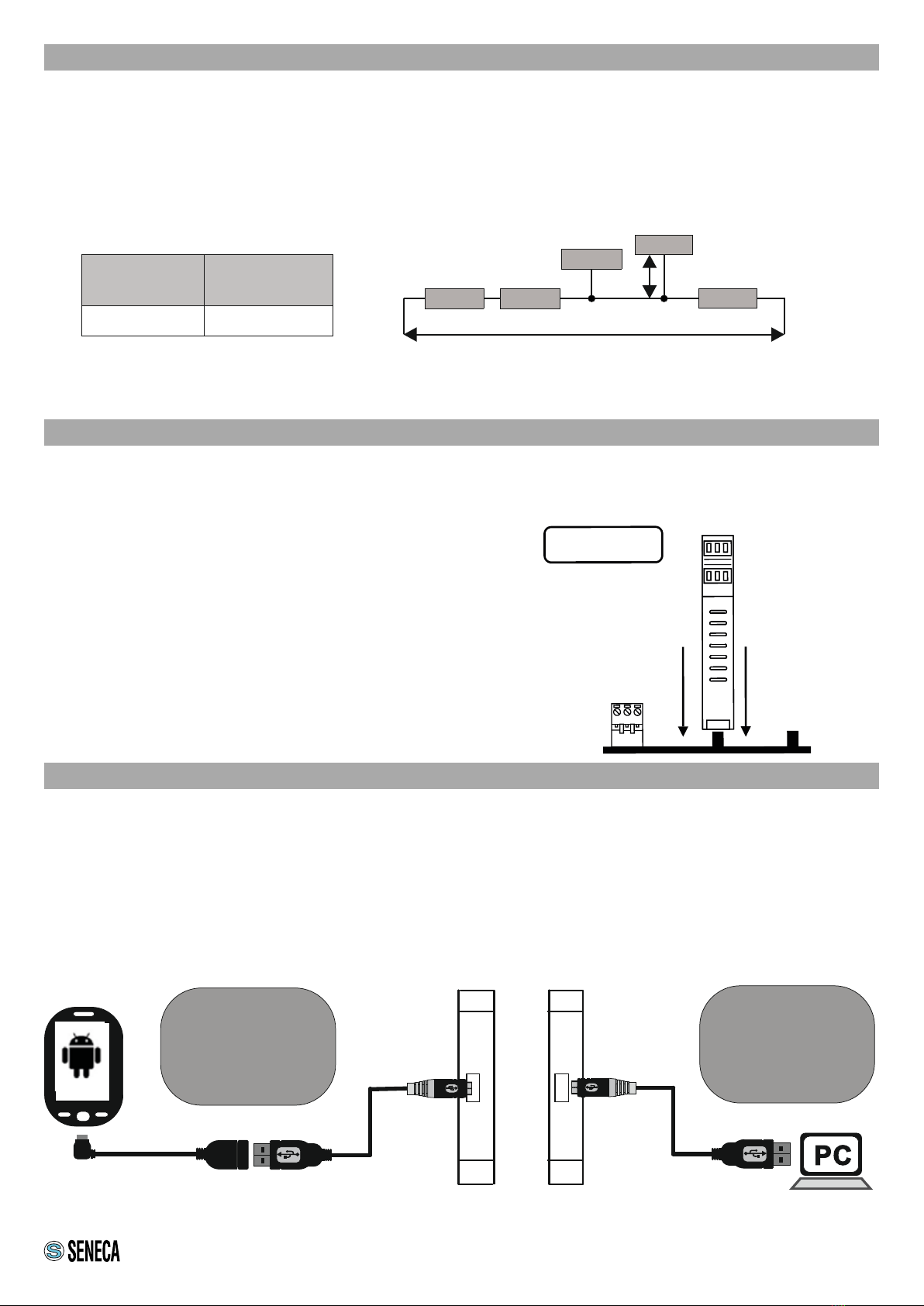
The module can also be programmed through the front connector (USB) and making sure you set the following
parameters for the connection: Address = 001, Baud rate = 2400, PARITY = none, STOP BIT = 1.
The USB communication port behaves exactly like that of the RS485 bus except for the communication
parameters as already described. It also has priority over the RS485 port and is closed after about 15 seconds’
inactivity.
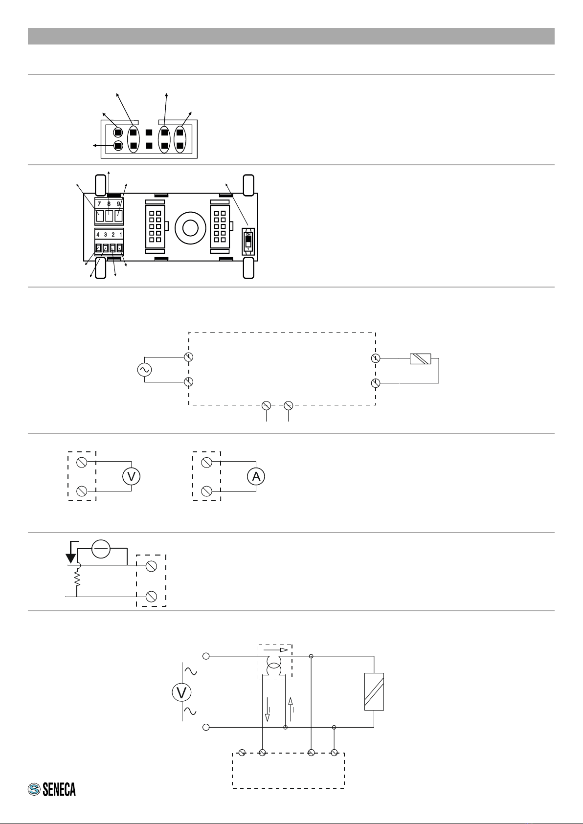
SERIAL INTERFACE
For detailed information on the RS485 serial interface, refer to the documentation on the www.seneca.it site, in the
Products / Z-PC Series / MODBUS TUTORIAL section.
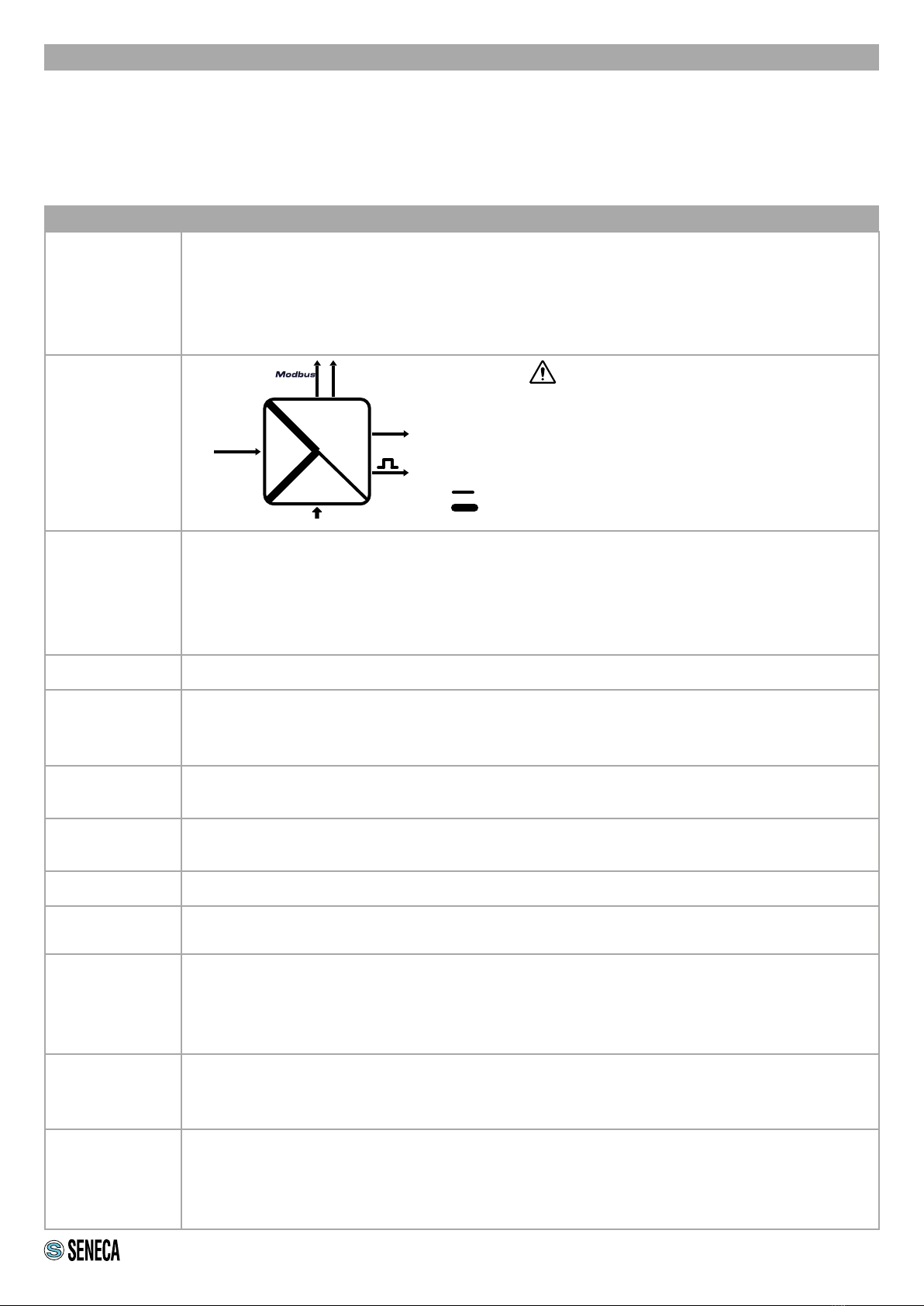
OPERATING LOGIC
The module provides, in the appropriate MODBUS registers, the values of the following electrical quantities: Vrms,
Irms, Watt, Var, Frequency, Energy, Cosɸ.
Except for energy, these measurements are available both in oating point format and normalized between 0 -
+10000 (0 - +10000 for absolute values of VAR and cosΦ, 350..750 for frequencies between 35.0 Hz and 75.0
Hz). The module retransmits as output, as a current or voltage signal, one of the previous quantities chosen by
the user (excluding energy). The range of the retransmitted output is proportional to the full scale value of the
measured quantity. For example, if the retransmitted signal is in current 4 - 20 mA and the quantity to retransmit
the voltage Vrms, we will have that 4 mA will correspond to 0 V, and 20 mA will correspond to 500 V, this being the
full scale for rms voltages.
You can also choose retransmission scaling: 100%, 50 % or 25 %. Getting back to the previous example but
setting a 50% retransmission scaling, 4 mA will correspond to 0 V and 20 mA will correspond to 250 V. The
retransmission values saturate at about 11 V for voltage outputs and at about 21 mA for current outputs.
At start-up the appropriate calibration coefcients are taken (depending on the choice of 50 or 60 Hz frequency).
All settings are loaded when the module is reset. The stored energy values are saved in FeRAM memory, so they
are not lost in case of power failure.
It should be noted that the Vrms, Irms, Active Power and frequency values are obtained by direct measurement,
while the Energy, Reactive Power and cosf values are calculated.
The measured active power can only be greater than or equal to zero. An example: if the reactive power is -2500
VAR or +2500 VAR (physical value, electrical network), the corresponding numerical value is +10000 and the
analogue output (available at the terminals) is +10 V (if SW2-2,3 = "00"). If the reactive power is 0 VAR (physical
value), the corresponding numeric value is 0 and the analogue output (available at the terminals) is 0 V (if SW2-
2,3 = "00"). Cos has the same behaviour as reactive power. For measurement and retransmission ranges in the
case of 50% and 25% scaling, refer to the tables in the USER MANUAL.