ENGLISH - 1/20MI001503-E
S311D-XX-L / S311D-XX-H Line
Advanced Digital Indicators-Totalizers
4, 6, 8, 11 Digits Display
Universal opto isolated digital input; admitted types: reed, npn (2 wires or 24 V), pnp (24 V),
NAMUR, photoelectric, Hall, 24 V input, TTL, variable reluctance.
Digital input signal frequency measurement from 0.00015 Hz to 10 kHz.
Increment or decrement totalizing of the digital input signal.
View of the frequency measurement and/or totalized value.
Programmable retransmission of the input value frequency by the isolated analog output
(voltage or active/passive current).
Retransmission of the totalized value by the isolated digital output (Open Collector).
Totalizer value is saved on non-volatile memory.
Filter programmable at 20 levels to stabilise reading.
Totalizer reset by auxiliary digital input, buttons pressureor Modbus register.
4, 6, 8 or 11 (4+7) Digits display.
In case of optional card use, two relay alarms are activable on the input measurement
frequency (maximum, minimum, automatically resettable or not).
Alarms status visible through two leds on the frontal panel.
RS485 serial communication with MODBUS RTU protocol (by optional board), maximum
32 nodes.
Two relay outputs (available on the optional card) for alarms signalling.
Easy navigation on the programming Menu by three buttons on the frontal panel.
Quick configuration of the alarm thresholds by the Quick Alarms Menu.
Display contrast settable.
Very Low Frequency Mode (VLF) automatically set if fmax £ 1 Hz.
1. GENERAL SPECIFICATIONS
2. TECHNICAL SPECIFICATIONS
Analog Output:
Digital Input:
Absorbed Current:
VMAX:
Sensors Power Supply:
Frequency Range:
Frequency Resolution:
Power Supply:
Generated Current: 0 - 20 mA, max load resistance: 500 W.
Voltage: 0 - 10 V, min load resistance: 1 kW.
Configurable Start and Full scale values.
Resolution: 2 mA / 1 mV.
-Reed
-npn 2 wires
-npn 24 V (3 wires)
-pnp 24 V (3 wires)
-NAMUR
-Photoelectric
-Hall
-24 V Input
-TTL
-Variable Reluctance
Max 7 mA
28 VDC
17 VDC
0.00015 Hz - 10 kHz
< 0.05 %
Code S311D-XX-L: 10-40 VDC, 19-28 VAC 50-60 Hz, max 3 W.
Code S311D-XX-H: 85-265 VAC 50-60 Hz, max 3 W.
EN
3. FUNCTIONING DESCRIPTION
The digital input frequency measurement or the totalizer value is translated into an analog or
digital output signal.
The frequency value or as an alternative the totalizer value is displayed; on the 11 (4+7) digits
model, both the values are simultaneously displayed (4 digits: frequency value, 7 digits:
totalizer value). The values are also available via Modbus RTU protocol upon query by RS485
bus (by the optional card).
3.1 Setting Modalities
All the parameters of the instrument may be set by the Programming Menu or RS485 (by the
optional card). The alarms thresholds may be quickly set by the Quick Alarm Menu. Besides
the Z-NET3 software has been developed for the programming and the configuration of the
module (consult the web site www.seneca.it).
Environmental Conditions:
Isolation:
Connections:
Protection:
Dimensions (L x W x H)
Standards:
Temperature: -10 - +60°C
Humidity min: 30%, max 90% at 40°C non condensing.
Storage Temperature: -20 - +85 °C.
1500 VAC among each pair of ports (included the optional
card ports).
-Removable screw terminals, 3.5 mm / 5.08 mm pitch .
-Three buttons for menu navigation.
IP65 (on the frontal with the apposite furnished seal).
98.2 x 88.5 x 48 mm
EN61000-6-4/2002-10 (electromagnetic emission, industrial
environment).
EN61000-6-2/2006-10 (electromagnetic immunity, industrial
environment).
EN61010-1/2001 (safety).
All circuits must be isolated from the other circuits under
dangerous voltage with double isolation. The power supply
transformer must comply with EN60742: “Isolated
transformers and safety transformers”.
Digital Output :
Error of Voltage / Current
output (referred to max
measuring range):
Type: Open Collector, Imax: 50 mA, Vmax: 30 V.
Calibration Error: 0.1 %
Thermal Coefficient: 0.01%/°K
Linearity error: 0.05 %
EMI (electromagnetic disturbance): < 1 %.
Auxiliary digital input : Opto isolated, Vmin: 10 V, Vmax: 30 V (available only by the
optional board).
Response Time: 5 ms.
Relay output: Capacity: 8 A / 250 VAC (available only by the optional board).
MI001503-E ENGLISH - 2/20
The instrument allows the following retransmission modalities:
Analog Output:The digital input frequency measurement is translated into an analog output
signal (voltage or current).
3.2 Retransmission Modalities
MI001503-E ENGLISH - 3/20
3.3 Alarms on the frequency measurement (by optional board)
Two alarms may be activated on the digital input frequency measurement. Each alarm may be
set on the following way:
1) Alarm on the minimum thershold. 2) Alarm on the maximum thershold.
3) Retained Alarm on the minimum threshold (the reset is not automatic).
4) Retained Alarm on the maximum threshold (the reset is not automatic).
For each alarm, it is possible to set Threshold and Hysteresys. If the alarm is set as high, the
alarm will turn OFF when the input value is Threshold-Hysteresys; instead if the alarm is set as
low, the alarm condition will end if the input value is Threshold+Hysteresys. The alarms status
is displayed by two leds on the frontal panel and by the relays (in case of optional card use).
The relays toggle at the alarm condition and return to the initial status at the end of the alarm
condition or at the reset (if retained). The retained alarms are reset by pressing the buttons UP
+OK/MENÙ for some seconds (on normal view functioning).
3.4 Totalizer
As an alternative to the digital input frequency measurement, it is possible to display the
totalizer value (saved on non-volatile memory). On the 11 digits (4+7) indicators both the
values are simultaneously available.
The totalizer may be:
-UP-counter: it is increased of a unit at each rising edge of the digital input.
-DOWN-counter: it is decreased of a unit at each rising edge of the digital input.
Once the maximum or minimum limit has been reached, the counting is reset and starts again.
Besides it is possible to set a reducing ratio the totalizer value will be divided for; so the
resulting value will be displayed.
The reset may be performed on the three following ways:
-By the auxiliary digital input (if enabled).
-By the pressure of the three buttons simultaneously for some seconds (if enabled).
-Via Modbus register.
Digital Output: The output generates an impulse at every increment / decrement of the
totalizer
At the raising of the counting frequency (up the
maximum value above indicated), pulses are lost until an always low output is obtained. The
output is normally at high logic level.
. An impulse with duration >= ~100 ms is generated. The output follows the totalizer up
to approximately 4.7 Hz maximum frequency.
Three Functioning Types may be set (except for the 11 digits indicators which display both
the frequency value and the totalized value) which define the view modalities:
1) Type 0: both frequency and totalizer value view.
By pressing the UP button for some seconds the frequency measurement view is
selected, instead by pressing DOWN for some seconds the totalized value is displayed.
At the passage to the frequency value the writing IST appears for some seconds, while
passing to the totalized value, the writing TOT appears.
2) Type 1:only frequency measurement view.
3) Type 2:only totalizer value view.
3.5 Frequency measurement value or totalized value display
3.6 Average and filter on the frequency measurement
It is possible to calculate the frequency measurement average on a settable number of
samples.
The mean value is then filtered by a 20 levels exponential filter and so displayed.
3.7 VLF Mode
If the Full scale value (in Hz) of the frequency measurement (HI-F) is £1 Hz the indicator shifts
to Very Low Frequency Mode (VLF) where the minimum frequency value detectable is equal to
0.00015 Hz (1 impulse every 111 minutes).
MI001503-E ENGLISH - 4/20
POWER SUPPLY: Verify the code on the label applied to the indicator.
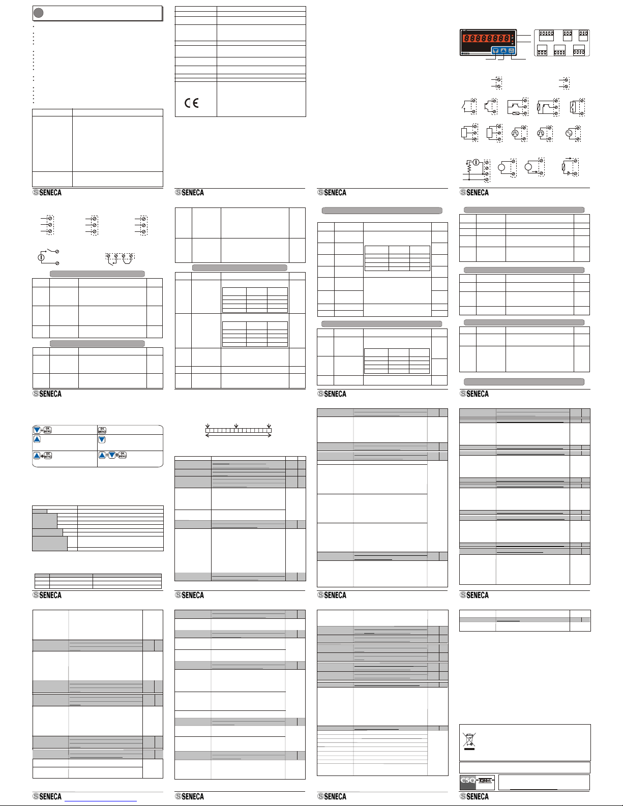
5. ELECTRICAL CONNECTIONS
RS485-Aux. Dig. Input
FRONTAL PANEL: BUTTONS / LEDS REAR SIDE: TERMINALS
Relay 2 Relay 1
Led
Led 222211111111101639528417
Alarm 1
Alarm 1
198
7
12A 2B 65
4
310
Power Supply Output Dig. Input
DOWN OK/MENÙUP
3.7 Password for access to the menu
4. BUTTONS AND TERMINALS POSITION
Terminals from 11 to 21 are present only in case of optional board use.
It is possible to enable the protection of the Programming Menu by password.
The Quick Alarm Menu is instead password free.
3.0 W
10 ÷ 40 VDC
19 ÷ 28 VAC
1
2A
Code S311D-XX-L
3.0 W
85 ÷ 265 VAC
1
2B
Code S311D-XX-H
Voltage
VV
+
ANALOG OUTPUT
Generated Current Ext. Power Supply
AA
+
5
44
4
33
+
DIGITAL INPUT
Reed
10 10
-
10
-
S8
+
88
+
7
+
10
8
-
10
7
9
S
+++
10 10 9
9 9 8
10
7
8
S
+
+
10
7
9
-
S
V
V > 100 mV
pk pk
+
DIGITAL OUTPUT
+
VV
5
6
4
3
RR
-
Imax=V/R=50 mA
II
Active Output (powered)
to connect to passive
inputs.
Unpowered passive
output to be connected to
active inputs.
npn 2 wires npn 24 V (3 wires) NAMUR
pnp 24 V (3 wires)
Photoelectric Hall 24 V Input TTL Input Variable
Reluctance
The 17 VDC internal power supply for the sensors, is available by 7 (+) and 10 (-) terminals.
MI001503-E ENGLISH - 5/20
11
12
13 16
RS485 Relay Output 1 (8 A/250 Vac) Relay Output 2 (8 A/250 Vac)
N.C. N.C.
N.A. N.A.
Com. Com.
Auxiliary Digital Input:
Totalizer Reset (external
power supply)
17
18 D-
D+
+
15
14
24 V
OPTIONAL BOARD CONNECTIONS
Example of Totalizer Reset by the auxiliary digital
input, internally supplied by the module
17 710 18
Parameters settable from Menu :
19
20
21
B
A
GND
6. MENU PARAMETERS
Parameter
Symbol
Parameter Name Description and setting range Default
Value
5477:
Password
disabled
Parameters settable from Menu :
V ext
FUNC
IRES
PASS
C.O.N. F.
I.n.P. t.
Indicator
Functioning Type
Enables the reset
of the totalizer by
buttons and
auxiliary digital
input
0 = function of frequency measurement and
totalizer view.
1 = only function of frequency measurement
value view.
2 = only function of totalizer view.
0 : Freq.
and Tot.
0 :
Enabled
0 = enables the reset of the totalizer from panel
and auxiliary digital input.
1 = disables the reset of the totalizer from panel
and auxiliary digital input.
Enables the
Password for the
access to menu
Setting a value different from 5477, the
password (always 5477) will be required at the
start of the menu.
Full Scale Value
(Hz)
3: npn
24 V
(3 wires)
1000 Hz
TYPE
HI-F Full scale value of the frequency measurement.
It defines also the frequency value of the digital
input signal, associated to the display
maximum value (HI-D).
Default
Value
Description and setting rangeParameter NameSymbol
Parameter
Input type 1 = Reed
2 = npn 2 wires
3 = npn 24 V (3 wires)
4 = pnp 24 V (3 wires)
5 = NAMUR
6 = Photoelectric
7 = Hall
8 = 24 V Input
9 = TTL Input
10 = Variable Reluctance
MI001503-E ENGLISH - 6/20
Selectable Values: 1 - 10.
0 = no filter
1 - 20
Filter level
1
3
Full scale value of the frequency measurement.
It defines also the frequency value of the digital
input signal, associated to the display
maximum value (HI-D).
1000 Hz
Decimal Point
position in HI-F
0 = no decimal point (ex: 00009999)
1 = first digit (ex: 0000999.9)
2 = second digit (ex: 000099.99)
3 = third digit (ex: 00009.999)
4 = fourth digit (ex: 0000.9999, only for 6 and 8
digits models)
Parameters settable from Menu :
Default
Value
Description and setting rangeParameter NameParameter
Symbol
Value displayed if the measured frequency is 0.
Value on the following ranges:
Start scale of
frequency
measurement view
0
Display
Digits Number Min. Limit Max. Limit
49999
-1999
Full scale of
frequency
measurement view
6999999
-199999
1000
899999999
-19999999
11 (4+7) 9999
-1999
0 = no decimal point (ex: 12345678),
1 =first digit(ex: 1234567.8) ... ...
N display digits-1
11 digits models (4 + 7): max number of decimal
digits equal to 3.
Decimal Point
position on
frequency
measurement view
0 = No
decimal
point
dPIn
LO-d
HI-d
dp_D
AVI
FILt
S.C.A. L.
0 = No
decimal
Point
Display
Digits Number Min. Limit Max. Limit
49999
-1999
6999999
-199999
899999999
-19999999
11 (4+7) 9999
-1999
Value displayed if the measured frequency is
HI-F. Value on the following ranges:
Number of samples
on which the
frequency average
is calculated.
MI001503-E ENGLISH - 7/20
Parameters settable from Menu : A.L.1. . / A.L.2. .
Alarm 1 Threshold
Alarm 1 Hysteresys
Display Digits
Number
8
6
4
11 (4+7)
99999999
999999
9999
9999
Min. Limit Max. Limit
-19999999
-199999
-1999
-1999
500
10
10
Default
Value
Description and setting rangeParameter NameParameter
Symbol
Alarm 2 Threshold
Alarm 2 Hysteresys
1000
0: Al 2
disabled
Value referred to the displayed frequency value
(decimal point set by dP_d).
Settable value on the following ranges:
Alarm 1 Type
Alarm 2 Type
0 = Alarm disabled
1 = Alarm on the minimum threshold
2 = Alarm on the maximum threshold
3 = Retained alarm on the minimum threshold
(the reset is not automatic)
4 = Retained alarm on the maximum threshold
(the reset is not automatic)
0: Al 1
disabled
Relay Functioning:
0 = normally opened relay (N.O.).
1 = normally closed relay (N.C.).
Relay 1: N.O./N.C.
Relay 2: N.O./N.C.
0: N.O.
0: N.O.
Alarm 1 parameters: accessible from A.L.1. . menu and identified by the final index 1.
Alarm 2 parameters: accessible from A.L.2. . menu and identified by the final index 2.
Frequency Display
Value associated to
the minimum value
of the output.
Parameter NameParameter
Symbol
Parameters settable from Menu :
Retransmitted
output type
Frequency Display
Value associated to
the maximum value
of the output.
Display Digits
Number
8
6
4
11 (4+7)
99999999
999999
9999
9999
Min. Limit Max. Limit
-19999999
-199999
-1999
-1999
0
Default
Value
Description and setting range
1000
Limits for the scaling of the retransmitted output.
Decimal point set by dP_d.
Settable values on the following limits:
1 = 0 - 10 V 2:
4 - 20 mA
2 = 4 - 20 mA
3 = 0 - 20 mA 4 = totalizer digital output
SET1
SET2
HYS1
HYS2
typ1
typ2
rLY1
rLY2
LO-T
HI-T
TYPe
O.U.T. .
MI001503-E ENGLISH - 8/20
MODBUS Address
Parameter NameParameter
Symbol
Parameters settable from Menu :
Serial
communication
speed
Parity control type
Delay on the
answer
1
Default
Value
Description and setting range
0: No
Delay
Settable values: from 1 to 255.
0 = 1200
1 = 2400
2 = 4800
0 =None 1= Even 2 =Odd. 0: None
Number of pauses of 6 characters each to be
entered between the end of the Rx message
and the start of the Tx. Settable values: 0..255.
3 = 9600
4 = 14400
5 = 19200
6 = 38400
7 = 57600
Serial communication speed in baud: 6: 38400
Parameters settable from Menu :
Display Contrast
Parameter Name
Parameter
Symbol
10
Default
Value
Description and setting range
Values from 1 (minimum contrast) to 20
(maximum).
Totalizer type:
UP-counter or
DOWN-counter.
0 = the totalizer increases of a unit at each rising
edge of the digital input.
1 = the totalizer decreases of a unit at each
rising edge of the digital input.
0: UP
1 = Overwrite the set values with the default
values.
Default Settings
Parameters settable from Menu :
Parameter Name
Parameter
Symbol Default
Value
Description and setting range
Totalizer Reducing
Ratio
1
It sets the value the totalizer will be divided for.
Admitted Values: 1 - 250.
Decimal point
position on the
totalizer view.
0 = no decimal point (ex: 123456)
1 = first digit (ex: 12345.6)
2 = second digit (ex: 1234.56)
....
N display digits-1.
11 digits models (4 + 7): max number of decimal
digits equal to 6.
0: No
decimal
point
By confirming with OK/MENÙ, all the parameters are saved in
flash memory and after some instants the module is reset.
Addr
PAR
DEL
BAUD
CONT
UPDN
DFLT
RATI
DP_T
E.X.I.T.
T.O.t. .
S.Y.S. .
b.U.S. .
ENGLISH - 13/20MI001503-E
11. ORDER CODES
Code
Model
Display
Power Supply
Options
Description
S311D Indicator - totalizer with universal digital input.
-4 4 digits
6 digits
8 digits
4+7 digits
85..265 VAC
10..40 VDC / 19..28 VAC
Optional card: RS485 ModBus Port, 2 relay alarms and
auxiliary digital input.
Isolation: 1500 VAC among each port
Calibration and configuration Service.
-6
-8
-11
-H
-L
-O
/T
9. SUMMARY OF BUTTONS ACTIONS (in view mode)
Access to Programming
Menu Access to Quick Alarms Menu
RetainedAlarmsreset.
Totalizer Reset (if this functionality has been
enabled by setting IRES=0).
By pressing the button for some
seconds and if FuNC=0 has been set,
the indicator switches to the frequency
view (except 11 digits model).
On the following table we give a summary of the actions which may be performed during the
view phase (not programming phase). To effectively execute the actions, it is necessary to
press the buttons for some seconds.
nnnn: Frequency Measurement value to display > HI-d value of the 2.5% or if the frequency
value > maximum displayable.
The errors are directly viewed through display.
We are going to list all the possible signallings with the correspondent meaning:
10. ERROR SIGNALLINGS
EERR: at the start may signal an error on the calibration memory. The functioning of the
module is blocked while the Modbus communication is available (if optional card).
The S311D-XX-L and S311D-XX-H lines indicators have MODBUS 16 bits (words) registers,
accessible by RS485 serial communication (available in case of optional card use).
12.1 Supported MODBUS Commands
Code
03
06
16
Function
Read Holding Registers
Write Single Register
Write Multiple Registers
Description
Reading of word registers up to 16 at a time.
Writing of a word register.
Writing of word registers up to 16 at a time.
12. MODBUS REGISTERS (Optional Card)
MI001503-E ENGLISH - 14/20
Set the digital input type:
1 : Reed
2 : npn 2 wires
3*: npn 24 V (3 wires)
4 : pnp 24 V (3 wires)
5 : NAMUR
Description IND. R/W
Bit [15:8]: module ID (38 decimal)
Bit [7:0]: external firmware revision
Register containing the internal code of the
firmware.
Register for the setting of the input type and of
the samples number on which the frequency
average is calculated.
40003
40002
40001 R
R
R/W
REGISTER
MACHINE ID
FW_CODE
TYP_INP/AVI
Bit [15:8]
Bit [7:0] Set the samples number on which the frequency
measurement average value will be calculated.
Admitted Values: 1*-10.
6 : Photoelectric
7 : Hall Sensor
8 : 24 V Input
9 : TTL Input
10 : Variable reluctance
HI_D_LONG_MSW Full Scale value of frequency measurement
view (Most significant word). R/W40004
Bit [15:0] Set the full scale value of the frequency
measurement view scale (integer, most significant
word): display value associated to Hi-F value
(40009-10) of the input frequency. The decimal point
on the set integer value is given by dP_d (40008).
Default: 1000.
Minimum Value (depending on the digits number):
4 Digits:-1999 6Digits: -199999
8 Digits: -19999999 11 (4+7) Digits: -1999
Maximum Value (depending on the digits number):
4 Digits:9999 6Digits: 999999
8 Digits: 99999999 11 (4+7) Digits: 9999
40005 R/W
HI_D_LONG_LSW Full Scale value of frequency measurement
view (Least significant word).
In the table the notation Bit [x:y] indicates all bits from x to y. For example Bit [2:1] indicates
bit 2 and bit 1, and serves to illustrate the meaning of the various united combinations of
the values of the two bits. Default values are indicated with the * symbol.
15 14 13 12 11 10 9 8 7 6 5 4 3 2 1 0
Most significant Bit Least significant bit
Bit Index
Word (16 bits): MODBUS Register
The 16-bit Holding Registers have the following structure:
12.2 Holding Registers
MI001503-E ENGLISH - 15/20
LO_D_LONG_MSW
LO_D_LONG_LSW
Start Scale value of frequency measurement
view (most significant word).
Start Scale value of frequency measurement
view (Least significant word).
R/W
R/W
40006
40007
Bit [15:0] Set the start scale value of the frequency
measurement view scale (integer, most significant
word): display value associated to a null input
frequency. The decimal point on the set integer
value is given by dP_d (40008).
Default: 0. The limits are the same of HI_D_LONG
(40004-5).
Decimal point position on the view of the frequency
measurement (dp_D):
0* = no decimal point (ex: 12345678) ,
1 = first digit (ex: 1234567.8), 2 = second digit
.....
N display digits-1.
11 digits (4+7): maximum number of decimal digits
equal to 3.
Decimal point position on Hi-F parameter (40009-
10) (dp_IN):
0* = no decimal point (ex: 12345678) ,
1 = first digit (ex: 1234567.8), 2 = second digit
.....
Maximum number of decimal digits depending on
the display digits number:
4 digits: 3, 6 digits: 4, 8 digits: 4, 11 digits (3+7): 3
Not used.
Bit [3:0]
Bit [7:4]
Decimal point position on the totalizer view
(dp_TOT):
0* = no decimal point (ex: 12345678)
1 = first digit (ex 1234567.8), 2 = second digit
.....
N display digits-1.
11 (4+7) digits indicators: maximum number of
decimal digits equal to 6.
DP_D/DP_IN/DP_TOT Decimal point position on the frequency, HI-F
parameter and totalizer values. R/W40008
Bit [11:8]
Bit [15:12]
Full scale of frequency measurement in Hz (integer,
most significant word): associated to the view
frequency full scale HI_D_LONG (40004-5). The
decimal point on the set integer value is decided by
dP_IN (40008). Default: 1000. The maximum and
minimum limits are the same of HI_D_LONG
(40004-5).
Bit [15:8]
HI-F_LONG_MSW Full scale of frequency measurement in Hz
(Most significant Word).
R/W40009
MI001503-E ENGLISH - 16/20
SET1_LONG_MSW
SET2_LONG_MSW
SET1_LONG_LSW
SET2_LONG_LSW
Alarm 1 Threshold (most significant word).
Alarm 2 Threshold (most significant word).
Alarm 1 Threshold (least significant word).
Alarm 2 Threshold (least significant word).
R/W
R/W
R/W
R/W
40011
40015
40012
40016
Bit [15:0]
Bit [15:0]
Alarm 1 threshold: value referred to the frequency
view scale but without decimal point.
For example if the value referred to the view scale is
20,0 set 200.
See HI_D_LONG (40004-5) for the maximum and
minimum limits of the parameter . Default: 500.
Alarm 1 threshold: value referred to the frequency
view scale but without decimal point.
For example if the value referred to the view scale is
20,0 set 200.
See HI_D_LONG (40004-5) for the maximum and
minimum limits of the parameter. Default: 1000.
HI-F_LONG_LSW Full scale of frequency measurement in Hz
(Least significant Word).
R/W40010
HYS1_LONG_MSW
HYS2_LONG_MSW
Alarm 1 Hysteresis (most significant word).
Alarm 2 Hysteresis (most significant word).
R/W
R/W
40013
40017
Bit [15:0]
Bit [15:0]
Alarm 1 hysteresis. Value referred to the frequency
view scale but without decimal point. For example if
the value referred to the view scale is 10,00 set
1000.
See HI_D_LONG (40004-5) for the maximum and
minimum limits of the parameter. Default: 10.
Alarm 2 hysteresis. Value referred to the frequency
view scale but without decimal point. For example if
the value referred to the view scale is 10,00 set
1000.
See HI_D_LONG (40004-5) for the maximum and
minimum limits of the parameter. Default: 10.
HYS1_LONG_LSW
HYS2_LONG_LSW
R/W
R/W
40014
40018
Alarm 1 Hysteresis (least significant word).
Alarm 2 Hysteresis (least significant word).
Bit [15:8]
TYP_AL1/TYP_AL2 Setting of alarms functioning. R/W40019
Set the Alarm 1 functioning:
0* = Alarm disabled
1 = Alarm on the minimum threshold
2 = Alarm on the maximum threshold
3 = Retained alarm on the minimum threshold (reset
is not automatic)
4 = Retained alarm on the maximum threshold
(reset is not automatic)
MI001503-E ENGLISH - 17/20
HI_T_LONG_MSW
HI_T_LONG_LSW
Displayed frequency value corresponding to
the maximum output value (most significant
value).
Displayed frequency value corresponding to
the maximum output value (least significant
value).
R/W
R/W
40020
40021
Bit [15:0] Displayed frequency value corresponding to
retransmitted output maximum value.
Set the value referred to the view scale but without
decimal point. Example: if the value referred to the
view scale is 10,0, set 100.
Default: 1000.
The maximum and minimum limits are the same of
HI_D_LONG (40004-5).
LO_T_LONG_MSW Displayed frequency value corresponding to
the minimum output value (most significant
value).
R/W40022
Bit [15:0]
LO_T_LONG_LSW Displayed frequency value corresponding to
the minimum output value (least significant
value).
R/W40023
Bit [7:0] Set the Alarm 2 functioning:
0* = Alarm disabled
1 = Alarm on the minimum threshold
2 = Alarm on the maximum threshold
3 = Retained alarm on the minimum threshold (reset
is not automatic)
4 = Retained alarm on the maximum threshold
(reset is not automatic)
Displayed frequency value corresponding to
retransmitted output minimum value.
Set the value referred to the view scale but without
decimal point. Example: if the value referred to the
view scale is 10,0, set 100.
Default: 0.
The maximum and minimum limits are the same of
HI_D_LONG (40004-5).
Bit [7:0]
CONTRAST/RATIO Register for the setting of the display contrast
and of the totalizer reducing ratio.
R/W40024
Bit [15:8]
Set the value the totalizer will be divided for.
Admitted values: 1 - 250.
Default: 1.
Set the display contrast: values from 1 (minimum
contrast) to 20 (maximum contrast). Default: 10
MI001503-E ENGLISH - 18/20
UP_DOWN/TYP_OUT/
FILT
RLY1_AL1/RLY2_AL2
Setting of Totalizer (UP or DOWN-counter),
retransmitted output type, Filter.
Sets the normal status of relay outputs 1 and 2
(if optional board).
R/W
R/W
40028
40027
Bit [15:12]
Bit [15:8]
Bit [7:0]
Bit [15:8]
BAUDR / DELAY Register for the baud rate and the answer
delay time setting. R/W40030
00000000 (0x00):1200
00000001 (0x01): 2400
00000010 (0x02): 4800
00000011 (0x03): 9600
00000100 (0x04): 14400
00000101 (0x05): 19200
00000110 (0x06)*: 38400
00000111(0x07): 57600
Serial communication speed in baud:
PASSWORD Enables / disables the password for the
access to the Programming Menu.
R/W40025
Bit [15:0] By setting a value different from 5477, at the start of
the programming menu, the password will be
required (always 5477). Default: 5477.
Set the relay 1 functioning (if optional board):
0* = normally opened relay.
1 = normally closed relay.
Set the relay 2 functioning (if optional board):
0* = normally opened relay.
1 = normally closed relay.
Retransmitted output type:
1 = 0 - 10 V output
2* = 4 - 20 mA output
3 = 0 - 20 mA output
4 = totalizer impulsive digital output.
Set the filter level.
Admitted Values: 0 = no filter, 1 - 20. Default: 3.
Bit [7:0]
Bit [11:8]
Set the the totalizer as UP-counter or DOWN-
counter:
0*= the totalizer increases of a unit at each rising
edge of the digital input.
1 = the totalizer decreases of a unit at each rising
edge of the digital input.
Register for the setting of module address and
parity control.
ADDR_PAR R/W40029
Set the address of the module. Admitted values from
0x00 a 0xFF (decimal values on the range 1-255,
Default: 1).
Bit [15:8]
Set the control parity:
00000000 (0)*: no parity (NONE)
00000001 (1): even parity (EVEN)
00000010 (2): odd parity (ODD)
Bit [7:0]
MI001503-E ENGLISH - 19/20
R
R
R
R
R
R
R
40041
40043
40045
40042
40044
40046
40047
FREQ_LONG_MSW
TOT_LONG_MSW
FREQ_FLOAT_MSW
FREQ_LONG_LSW
TOT_LONG_LSW
FREQ_FLOAT_LSW
FREQ_SHORT
Displayed value of the frequency measurement
(Long format, most significant word).
Totalizer value (Long format, most significant
word).
Frequency Measurement value in Hz (Floating
Point Format, most significant word).
Displayed value of the frequency measurement
(Long format, least significant word).
Totalizer value (Long format, least significant
word).
Frequency Measurement value in Hz (Floating
Point Format, least significant word).
Bit 1 1: The events (rising edges of the digital input) occur
with too high frequency and the instrument
suspends temporarily the measurement.
STATUS Errors and alarms Signalling. R40048
Bit [15:9] Not used
Bit 8 1:Alarm 2 ON.
Bit 7 1:Alarm 1 ON.
Bit 6
Bit 5 1: the value to display is > HI-d of the 2,5 %.
Bit 4
Bit 3 1:Failure on totalizer saving.
Bit 2
Response delay time. It represents the number of
pauses of 6 characters each to be entered between
the end of the Rx message and the start of the Tx
message. Default value: 0.
Bit [7:0]
Frequency measurement in 0-10000 scale.
Not used.
Not used.
Not used.
Frequency measurement in 0..10000 scale.
0: if the displayed value FREQ_LONG (40041-42) is
equal to LO_T_LONG (40022-23, frequency
displayed value corresponding to the retransmitted
output minimum value).
10000: if the displayed value FREQ_LONG
(40041-42) is equal to HI_T_LONG (40020-21,
frequency displayed value corresponding to the
retransmitted output maximum value).
Limited: 0..+11000.
MI001503-E ENGLISH - 20/20
-By writing 0xC1A0 (decimal 49568), reset
command.
Bit [15:0]
Module Reset.
RESET R/W40049
Bit 0 1: Calibration Eeprom is damaged.
Contact Seneca srl to solve the problem.
SENECA s.r.l.
Via Germania, 34 - 35127 - Z.I. CAMIN - PADOVA - ITALY
Tel. +39.049.8705355 - 8705359 - Fax +39.049.8706287
THEINTERNATIONAL CERTIFICATIONNETWORK
R
ISO9001-2000
This document is property of SENECA srl. Duplication and reprodution are forbidden, if not authorized. Contents
of the present documentation refers to products and technologies described in it. All technical data contained in the
document may be modified without prior notice Content of this documentation is subject to periodical revision.
Disposal of Electrical & Electronic Equipment (Applicable throughout the European Union and
other European countries with separate collection programs)
This symbol, found on your product or on its packaging, indicates that this product should not be
treated as household waste when you wish to dispose of it. Instead, it should be handed over to an
applicable collection point for the recycling of electrical and electronic equipment. By ensuring this
product is disposed of correctly, you will help prevent potential negative consequences to the
environment and human health, which could otherwise be caused by inappropriate disposal of this
product. The recycling of materials will help to conserve natural resources. For more detailed
information about the recycling of this product, please contact your local city office, waste disposal
service or the retail store where you purchased this product.
By pressing the button for some
seconds and if FuNC=0 has been set,
the indicator switches to the totalizer
view (except 11 digits model).