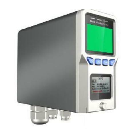
SENKO SP-MGTP User manual

SP-MGTP
(Portable Multi Gas Detector with Pump)
www.senko-detection.com
USER MANUAL

Product Overview
SP-MGTP is a portable multi gas detector with a built-in pump which warns of a dangerous gas
environment. The detector indicates the concentration of up to 6 gases including oxygen, carbon monoxide,
hydrogen sulphide, carbon dioxide, and other toxic and combustible gases simultaneously on the LCD
display. It is easy and simple to operate. The device alerts the operators of danger with an audible, visible,
and vibration alarm when the concentration exceeds safe gas levels. The device shows the gas
concentration in real time and identifies the maximum and minimum concentrations. The settings can be
modified through the SENKO IR-LINK (option).
Warning
➢Please do not replace or change any parts. Unauthorised replacement of parts and/or maintenance will
invalidate the warranty.
➢Please remove any debris on the surfaces of the sensor, LED or buzzer / pump hole before use.
➢Test the performance of the gas sensor using bump test and using calibration gas regularly. The gas
should trigger an alarm to be successful.
➢Test whether the LED, alarm and vibration function properly on a regular basis.
➢Using the device in conditions outside the certified temperature, humidity and pressure range may
cause the instrument to malfunction or fail.
➢The sensors inside the device may indicate the gas concentration differently according to the
temperature, pressure and humidity they are in. Please make sure to calibrate the detector in the same
environment in which it will be used.
➢Extreme changes in temperature may cause drastic changes of the gas concentration. (e.g. using the
detector where there is a huge gap between the inside and outside temperature) Please use the device
when the concentration becomes stable.
➢Severe pressure or impact may cause drastic changes of the gas concentration. Therefore, please use
the device when the concentration is stable. Severe pressure or impact may cause also malfunction in
the sensor or the device.
➢The alarms are set according to the international standard and must be changed by an authorized
expert.
➢Charging or replacing the battery must be done in a safe area where there is no risk of explosion or
fire. The use of spare parts not supplied by the manufacturer will invalidate the warranty.
IR communication should only be done in a safe area where there is no risk of explosion or fire.
➢Do not expose the detector to poisons such as alcohol and citrus based products, as poisons may
damage device’s accuracy and response time.
➢If you suspect sensor poisoning, bump test and calibrate the instrument before further use.
➢The detector is designed for use only in potentially explosive atmospheres where oxygen concentrations
do not exceed 20.9% (v/v). Oxygen deficient atmospheres (<10% v/v) may suppress some sensor
outputs.
➢Recharge the battery before it is discharged.
➢Charge the detector in temperature ranged from 0°C to 40°C

➢The efficiency of the rechargeable battery decreases by approximately 20% after two years of normal
use.
➢Do not use any other charging adapter.
➢Do not calibrate the device while or immediately after charging the battery.
➢Do not calibrate if exposed to the condition representative of the IP rating.
➢Do not perform the calibration during the stabilization process after turning on the device.
➢Sudden changes in atmospheric pressure may cause oxygen concentration to vary temporarily.
➢Before daily use, check the pump port is clear of any obstructions, debris, or blockage.
If the pump port is blocked by any pollutants, the measured reading may be measured lower than the
actual concentration.
➢The equipment shall only be carried and must not be laid down unattended
➢If a charge-generating mechanism is present, the exposed metallic part on the enclosure is
capable of storing a level of electrostatic charge that could ignite IIC gases. Therefore, the
user / installer shall implement precautions, for example, those listed above, to prevent the
build-up of electrostatic charge. This is particularly important if the equipment is being used
in a Zone 0 environment.
➢The equipment shall only be charged while in the non-hazardous area, using a charger
specifically supplied for use with the unit (for example part number ICP12-060-1200D,
manufactured by Shenzhen Shi Ying Yuan Electronics Co, LTD), approved as SELV or Class 2
equipment against IEC 60950, IEC 61010-1 or an equivalent IEC standard. The maximum
voltage and current from the charger shall not exceed 6.3 Vdc plus tolerances and 1.2 A
respectively, and shall be further limited by the charging system to Um = 6.3 Vdc. The ambient
temperature during charging shall be in the range 0 °C to 45 °C.
➢The battery and sensors should only be replaced by SENKO authorized service providers in a safe zone,
free of hazardous gases
Caution
➢Please read the manual carefully.
➢The device is not a gas analyzer, but a gas detector designed to detect the presence of a gas.
➢If the instrument fails to pass calibration, stop using and consult the manufacturer.
➢Test the device every 30 days under the atmospheric environment of clean air without gases.
➢To clean the exterior of the device use only a soft cloth and do not use chemical detergents.
Reference
➢For flammable gas equipment installation, operation and maintenance information, please refer IEC
60079-29-2
➢Conversion for %LEL and %vol follows the ANSI/NFPA 497 standard.

Contents
1. Product Overview ..............................................................................................................................................................5
2 Activation...............................................................................................................................................................................6
2.1. Switch On............................................................................................................................................................................... 6
2.2. Switch Off .............................................................................................................................................................................. 6
3. Pump .......................................................................................................................................................................................6
3.1. Pump Test ................................................................................................................................................................................... 7
3.2 Filter Replacement ................................................................................................................................................................... 7
3.3 Regulator ...................................................................................................................................................................................... 7
4. Display ....................................................................................................................................................................................7
4.1. Measuring Mode ................................................................................................................................................................ 7
4.2. Display Mode ....................................................................................................................................................................... 8
4.2.1 Display Mode in Detail ...................................................................................................................................... 9
4.3. Alarm Display .....................................................................................................................................................................11
4.3. Battery Display...................................................................................................................................................................13
5. Setting and Operation ................................................................................................................................................. 13
5.1. Alarm Menu ........................................................................................................................................................................14
5.2. Calibration Menu..............................................................................................................................................................15
5.2.1. Span Calibration Environment............................................................................................................................15
5.2.2. Zero Calibration (Fresh Air Calibration) .........................................................................................................16
5.2.3. Span Calibration (Standard Gas Calibration) ...............................................................................................16
5.3. Test (Inspection) Menu ..................................................................................................................................................17
5.4. Set Menu..............................................................................................................................................................................18
6. Log......................................................................................................................................................................................... 19
7. Specification...................................................................................................................................................................... 19
7.1. Operating condition.............................................................................................................................................................19
7.2. Storage condition..................................................................................................................................................................20
7.3. Certification..............................................................................................................................................................................20
8. Failure / Escape................................................................................................................................................................ 22
9. Trouble-shooting............................................................................................................................................................. 23
10. Maintenance & Replacement...................................................................................................................................... 23
10.1. Charging..................................................................................................................................................................................23
10.2. Gas Cylinder ..........................................................................................................................................................................24
10.3. Battery......................................................................................................................................................................................24
10.4. Pump.........................................................................................................................................................................................24
10.5. Filter ..........................................................................................................................................................................................24

1. Product Overview
LCD display symbols
High Alarm
Fresh Air Calibration
Low Alarm
Device Stabilization &
Configuration View &
Calibration Succeeded
Alarm Condition
Standard Gas Calibration
STEL Alarm
Remaining Battery
TWA Alarm

2 Activation
2.1. Switch On
Press the power button for 2 seconds and SYS boot is displayed. Once the device turns on, the version
and LCD are displayed. After 10 seconds of system test, the warmup will begin.
If errors occur during system test, the device will indicate error code. (Regarding error code, please refer
to the Chapter 8(Failure and Escape).
The exact warmup time differs depending on which sensor types are fitted. After completing the warmup,
the device goes into the measurment mode.
2.2. Switch Off
To switch off, press and hold down the enter button for three seconds. The display counts down three
seconds with the “SYS OFF” message.
(The device will not be switched off only unless you keep pressing the button for longer than three
seconds.)
<Caution> To check the gas response performance of the sensor, it is recommended to do a bump test
with gas concentration higher than the alarm set point. It is recommended to do a bump test before
each use of the device. Users are required to check if the device is working properly and ensure the
pump port is clear of any obstructions, debris, or blockage.
Initial Setting Mode
Gas Measuring Mode

3. Pump
3.1. Pump Test
When you change the gas tube or reconnect to the detector, test the sampling system by blocking the
end of the tube. When the flow is blocked, the device will alarm every second. If no alarm activates this
indicates a leak in the system or a failure of the pump.
3.2 Filter Replacement
The gas inlet is protected by the particulate filter and membrane filter. When the filter is blocked, the
sampling system will be unable to work and the warning alarm will be activated sounding every second.
Visually inspect the filter to ensure the filter is free of debris or obstructions. Discolouration of the filter is
the best indicator that the filter needs replacing. If the filter needs to be replaced, loosen the two screws
and replace with new filters. After replacing with new filter, reassemble the screws and continue to use it.
3.3 Regulator
The detector has an internal pump drawing the gas, so when performing a calibration or bump test, a
demand flow regulator should be used on the gas cylinder.
4. Display
4.1. Measuring Mode

After stabilization the device goes into the normal measuring mode. The gas concentration and the battery
power level are displayed on the LCD display. Oxygen is displayed in %vol, combustible gases in %LEL and
H2S, CO in PPM (parts per million). When the gas concentration levels change, the value is displayed in
real time, and when the levels exceed the threshold for either LOW alarm or HIGH alarm (or TWA/STEL),
the display icons of
LOW
,
HIGH
,
TWA
or
STEL
flash regularly and the audible, visual and vibration alarms
activate.
When the concentration detected by the device returns below the alarm threshold, the alarms stop,
however the alarm icon continues to indicate that an alarm has occurred until the Enter button is pressed
to accept it.
4.2. Display Mode
Pressing the △ or ▽ button steps the display through fourteen different display modes as shown above.

4.2.1 Display Mode in Detail
LCD Display
Images
Description in Detail
➢Measuring Mode (Basic Display)
➢Display the current gas levels of the atmosphere and the battery
power level
➢A low gas alarm has been triggered.
*In an ambient air, the Oxygen level normally indicates 20.9%vol.
➢A high gas alarm has been triggered.
*In an ambient air, the Oxygen level normally indicates 20.9%vol.
➢A STEL (Short Term Exposure Limit) gas alarm has been triggered
indicating the 15 minutes average exposure has been exceeded
➢A TWA (Time weighted average) gas alarm has been triggered
indicating the 8 hours average exposure has been exceeded
➢Display the preset low alarm levels.

➢Display the preset high alarm levels.
➢Display the preset STEL levels.
➢Display the preset TWA levels.
➢Firmware Version, Current battery voltage, Current
temperature(Celsius)
➢Date / Time
➢Calibration Concentration Value

➢Last Calibration Date (01.01= January 1st)
➢Remaining time to next calibration date when the calibration
interval is configured.
(Default: N/A)
➢Remaining time to next bump test date when the bump interval
is configured.
(Default : N/A)
4.3. Alarm Display
Type
Trigger Condition
LCD Display
Alarm Sound & Vibration Display
(Every Second)
LOW Alarm
Exceed LOW alarm value
icon &
gas concentration
levels displayed
HIGH
Alarm
Exceed HIGH alarm value
icon &
gas concentration
levels displayed
TWA Alarm
Exceed TWA alarm value
icon &
gas concentration
levels displayed
STEL Alarm
Exceed STEL alarm value
icon &
gas concentration
levels displayed

LOW Alarm / HIGH Alarm activation: In the event of a High Alarm the user must leave the area immediately.
The audible, visual and vibration alarms stop when the device is in a safe area where the gas concentration
is normal.
TWA Alarm activation: The alarm activates when the average gas levels for the last eight hours exceed the
TWA concentration. The audible, visual and vibration alarms stop when the device is in a safe area where
the gas concentration is normal.
STEL Alarm activation: The alarm activates when the average gas levels for the fifteen minutes exceed the
STEL concentration. The audible, visual and vibration alarms stop when the device is in a safe area where
the gas concentration is normal.
Over Limit: When the detector is exposed to gas concentrations above the upper limit range, it will
display OVL (Over Limit) alarm on the display.
Under Limit: When the detector indicates a below zero value, it will display UL(Under Limit) & Zero
calibration warning on the display. The alarm will clear when a successful zero calibration is performed.
Note)
-If a gas alarm occurs, evacuate to a safe place, you should take appropriate action.
-The factory setting for gas alarms is non-latching. Latching alarms can be set up by using IR-LINK
(option) in computer.
-Description of any suppression of indication cans be changed using IR-LINK(option) in computer. (I
don’t understand what this is supposed to mean, I would suggest removing it)
Bump Test Interval (SENKO IR-LINK Options): Notices the user on a regular basis to check the device.
Calibration Interval (SENKO IR-LINK Options): Notices the user on a regular basis to calibrate the sensor
.
Bump Test
A bump test is now due
to be performed
Bump Display
“bump” blinking
Stops after Bump Test is
completed successfully
Execute
Calibration
A calibration is now due
to be performed
icon & Gas Title
Blinking
Stops after Calibration is
completed successfully
Over Limit
Exceeding the overrange
Limit for a sensor
Under Limit
Sensor is reading a
below Zero value
Stops after Zero Calibration

Self-Test Interval
(SENKO IR-LINK Options): Notices the user on a regular basis to Self-Test
4.3. Battery Display
The battery status is indicated by three icons: High, Medium, Low.
Low: When the battery icon indicates “low”, the detector will activate alarm every three minutes.
When the low battery point is reached, the detector will continue to operate for about 30 minutes.
End: When the battery icon indicates “end”, the detector will display “SYS L-Bat” for two seconds and then
it will turn off.
To charge the detector, plug in the charging adapter. During charging, the battery indicator will circulate.
<WARNING>
Do not charge the battery in an explosive atmosphere.
Do not charge the battery in a temperature range from 0 °C to 40 °C.
Use only the charging adapter provided by SENKO for charging the battery.
5. Setting and Operation
When pressing and holding △ + ▽ buttons for two seconds simultaneously, the detector will enter into
the setting mode. In the setting menu, the Alarm Menu, Calibration Menu, Test(Inspection) Menu, and Set
Menu will display and users can configure the setting by scrolling to the required menu and pressing the
power button in a menu.
In Setting Mode, the display will return to the measurement mode after the 10 seconds of inactivity.

5.1. Alarm Menu
In the alarm menu, press the power button and the device will enter the alarm setting mode.
In the alarm setting mode (ALR SET), pressing the △ or ▽ button, steps through four menus as below
and the user can enter and change or clear the previous MIN, MAX, TWA, and STEL alarms by pressing
the power button.
ALR SET : Low, High, STEL, TWA
MIN MAX CLR : Deletes the previously measured MAX and MIN levels.
STEL TWA CLR : Deletes the previously measured STEL and TWA levels.
ModE SET : Sets the alarm to Latch (where the device stays in alarm when a gas alarm is triggered
until the button is pressed to accept it) or Auto where the alarm stops when the reading returns to normal
levels.

5.2. Calibration Menu
In the calibration menu, when the power button is pressed, the zero and span calibration will be displayed.
Select the calibration mode(Zero or Span) by pressing △ or ▽ button and power button to enter the
mode.
To activate zero or calibration, press the power button.
Zero Run (Fresh Air Calibration) : Zero Calibration
SPAn Run (Standard Gas Calibration): Span Calibration
In the Span calibration mode, select a sensor to be calibrated by pressing on/off
Note :
If the sensitivity of each sensor has drifted below the standard accuracy, the calibration will fail.
If the detector is dropped or damaged, if any of the sensors are changed, or if the device fails a bump
test, a calibration must be performed.
5.2.1. Span Calibration
After selecting a sensor in the calibration mode, connect the tube as shown below. Ensure the tube is
connected properly and check the cylinder matches with the calibration setting levels.

<IMPORTANT>
As to a span calibration, if VOC(PID) sensor is included, perform the span calibration of PID(VOC) sensor
after other sensors are calibrated.
5.2.2. Zero Calibration (Fresh Air Calibration)
In the zero run mode, when pressing the power, the ON/OFF will be displayed. By pressing △or ▽, move
the sensor to be calibrated and select on or off. When you press the power button for three seconds, the
zero calibration will be performed with 10 seconds countdown. To abort the calibration, press the power
button. If the calibration fails, “FA” will be displayed. When the calibration fails continuously, stop using
the detector and contact the manufacturer or authorized agents for either sensor replacement or warranty.
<Sensor ON / OFF > < Countdown > < Success / Fail>
5.2.3. Span Calibration (Standard Gas Calibration)
In the “SPAn RUN” mode, when you press the power button, the ON/OFF will be displayed for each sensor.
Press the △ or ▽ button to select a sensor to be calibrated and the power button to select either on or
off, and then press the power button for three seconds to activate the calibration. The normal countdown
takes 90~180 seconds and each sensor has different calibration time. To abort the calibration, press the
<Caution> Before calibration, check the sensor warmup is completed. The device will display the normal
concentration when the warmup is complete. If normal concentrations are not being displayed, it
indicates the warmup is not complete and the calibration should not be performed.
<Caution> The calibration should be performed in a clean air environment, free of hazardous gases and
the hose length should be no longer than 0.9m.

power button. If the calibration fails, the failed gas will flash.
If the calibration continues to fail, contact SENKO or authorized agents to check either sensor replacements
or warranty.
<Caution> The initial calibration is completed at SENKO CO. Ltd. before the device is delivered. The
calibration values are saved in the device. Calibration using gas levels which are not the same as the
saved calibration value will impair the accuracy of the device performance. Normally, the calibration
should be done once a year after the purchase and regularly every six months thereafter.
<Caution> The device is calibrated on the assumption that oxygen concentration is 20.9%vol, the
combustible gas is 0%LEL, and the toxic is 0ppm in a clean air atmosphere, fresh air calibration must be
conducted in the same clean air without the presence of any other gases. Fresh air calibration in the
airtight spaces therefore is not recommended. Make sure to there is adequate ventilation for the exhaust
gases.
5.3. Test (Inspection) Menu
In the test menu, when pressing the power button, the self-test and bump test mode will be displayed.
In the SELF RUN mode, press the △ or ▽, and then select the desired function to test (LCD -> Buzzer ->
LED -> Backlight Yellow -> Backlight Red -> Motor -> Memory) and press the power button to activate
the test.
Self-Test : LCD -> Buzzer -> LED -> Backlight Yellow -> Backlight Red -> Motor -> Memory
In the BUMP RUN mode, press the power button to enter the mode, and then select the either on or off
for each sensor. Attached the tube and apply the gas once the countdown starts. If the test passes, “OK”

will be displayed. If the test fails, “FA” message will be displayed and the bump test message will flash in
the measurement mode.
<Sensor ON / OFF > < Countdown > < Pass / Fail>
IMPORTANT!
Ensure that all sensors are warmed up before performing the bump test. It will take some time to warm
up the sensors. You can distinguish the sensor warm up by looking at the sensor readings. If the detector
is not warmed up, the last segment will be blinking.
* When you perform the bump test, make sure to use the high concentration gas than 1st alarm level.
5.4. Set Menu
In the “set menu”, press the power button to enter into the mode, and then select from the four menus
below by pressing △ or ▽ button. To enter the mode, press the power button.
BL SET : Blacklight ON / OFF Setting
LED SET : LED ON / OFF Setting

BUZ SET : Buzzer ON / OFF Setting
Mot SET : Motor ON / OFF Setting
6. Log
During a normal operation, data, event, calibration, and bump logs are stored in the device. The stored
data can be downloaded via SENKO IR LINK with the PC program.
Up to 30 log events will be saved, and once the data is full, the oldest date will be overwritten automatically
and the new data will be stored. (First in-First out). The detector will save a data log every one minute in
clean air without hazardous gases. In the event of gas alarms or configuration changes, the data log will
be saved every one second.
7. Specification
The detector with a pellistor sensor(LEL) will operate continuously for more than 24 hours when fully

charged. The detector with an NDIR sensor(LEL, CO2) will operate continuously for around 2 months when
fully charged under normal operating conditions.
7.1. Operating condition
Log Categories
Log Details
EVENT(High, Low, TWA, STEL)
Alarm
Occurrence time, Duration, Alarm Type, Gas Concentration, Serial Number
BUMP TEST Log
Test date, Pass/non-pass, Calibration Gas Concentration, Detected
Concentration
Calibration Log
Date of the Calibration, Type, Calibration Gas Concentration, Detected
Concentration
Data Log
Time, Date of executing IR-LINK, Concentration, Alarm Types, Options
Model
SP-MGTP
Display
Segment LCD display, LCD Backlight, Indicator LED
Key
3 Operation and programming Keys
Sensor
Electrochemicals for Toxics and Oxygen , ppb and ppm PID , combustible LEL and NDIR ,
CO2 NDIR
Alarm
Visual : LCD alarm display, LCD Backlight,
Indicator LED Audible / buzzer (90dB at 10cm)
Data Saving
Event Log : 30 EA, Calibration Log : 30 EA
Bump Log : 30EA, Data log Two Months or longer
How to Fix
Belt Clip

7.2. Storage condition
7.3. Certification
√ FCC compliance
This device is tested according to FCC rules part 15 and complies with restrictions for a CLASS A digital device.
These restrictions are designed to provide adequate protection against an industrial environment which may cause
harmful interference during operation. This device generates, uses, and can radiate radio frequency energy and, if the
instruction manual is not followed correctly for installation or usage, it may cause interference to wireless
communications.
Temperature
-20˚C ~ +50˚C
Humidity
10 to 90% RH(Non-condensing)
Pressure
80 ~ 120KPa
Sampling
Built-in pump
Ingress
Protection
IP67 (IP ratings do not imply that the equipment will detect gas during and after exposure to
those conditions)
Battery Type
Rechargeable Lithium-Ion
Nominal Voltage : 3.7V, Nominal Capacity: 4000mAh , Max Charging Voltage: 6.3V
Battery
Duration
(=Operating
Time)
P0 Type : PID, LEL(Catalytic-CH4)
O2 + Toxic + LEL(Catalytic) + PID
≥20h
O2 + Toxic + LEL(Catalytic)
≥24h
N0 Type : PID, LEL(IR-CH4)
O2 + Toxic + LEL(IR) + PID
≥57h
O2 + Toxic + LEL(IR)
≥72h
N1 Type : PID, LEL(IR-CH4)
O2 + Toxic + LEL(IR) + PID
≥40h
O2 + Toxic + LEL(IR)
≥52h
N2 Type : PID, LEL(IR-CH4/CO2)
O2 + Toxic + LEL(IR) + CO2(IR) + PID
≥40h
O2 + Toxic + LEL(IR) + CO2(IR)
≥52h
00 Type : PID
O2 + Toxic + PID
≥57h
O2 + Toxic
≥72h
Case
TPU covered Poly Carbonate(PC)
Size
(W x D x H) 77mm x 146mm x 43mm
Weight
490 g
Options
SENKO IR-LINK
Model
SP-MGTP
Temperature
0 ~ 20℃
Humidity
15 ~ 90%RH (Non-condensing)
Pressure
90 ~ 110KPa
Shelf life
6months
Other manuals for SP-MGTP
1
Table of contents
Other SENKO Gas Detector manuals

SENKO
SENKO SI-100 User manual

SENKO
SENKO MGT User manual

SENKO
SENKO SP-MGTP User manual

SENKO
SENKO SP secure User manual

SENKO
SENKO SI-560D User manual

SENKO
SENKO SGT User manual

SENKO
SENKO iGas Detector CO2 User manual

SENKO
SENKO SGT-P User manual

SENKO
SENKO SI-100C User manual

SENKO
SENKO RAITEC SI-100D User manual