Sensit SCAL-400 User manual

CALIBRATION AND CHARGING STATION
SCAL-400
INSTRUCTION MANUAL
READ AND UNDERSTAND INSTRUCTIONS BEFORE USE
FOR USE IN AREAS KNOWN TO BE FREE OF COMBUSTIBLE GAS HAZARDS
FOR USE IN AREAS THAT ARE CLEAN AND DRY
851 Transport Drive
Valparaiso, IN 46383-8432
Phone: 888 473 6748
219 465 2700
Fax: 219 465 2701
Email: info@gasleaksensors.com
Web: www.gasleaksensors.com


TABLE OF CONTENTS
Specication ............................................................... 4
Features ..................................................................... 4
Description.................................................................. 5
LED Status ................................................................. 5
Main Screen ............................................................... 6
Details Status Screen.............................................. 7
Main Menu Screen ..................................................... 8
Calibration Gas Information Screen ........................ 8
Log Review Screen ................................................. 9
Password Screen .................................................... 9
Supervisor Menu Screen..................................10-12
Operation - Set-up................................................. 13
Operation - System Activation ............................... 13
Operation - P400 Testing....................................... 13
Warranty .................................................... Back Cover
SCAL-400
CALIBRATION AND CHARGING STATION
FOR USE WITH SENSIT® P400 GAS MONITORS

Specifications
Power:100–240VACinput
Size:24”X7”X3”(61cmX17.8cmX7.6cm)
Weight:5.75lbs.(2.6kg)
OperationalTemperature:40‐122°F(5‐50°C)
Maximuminletpressure:20psi
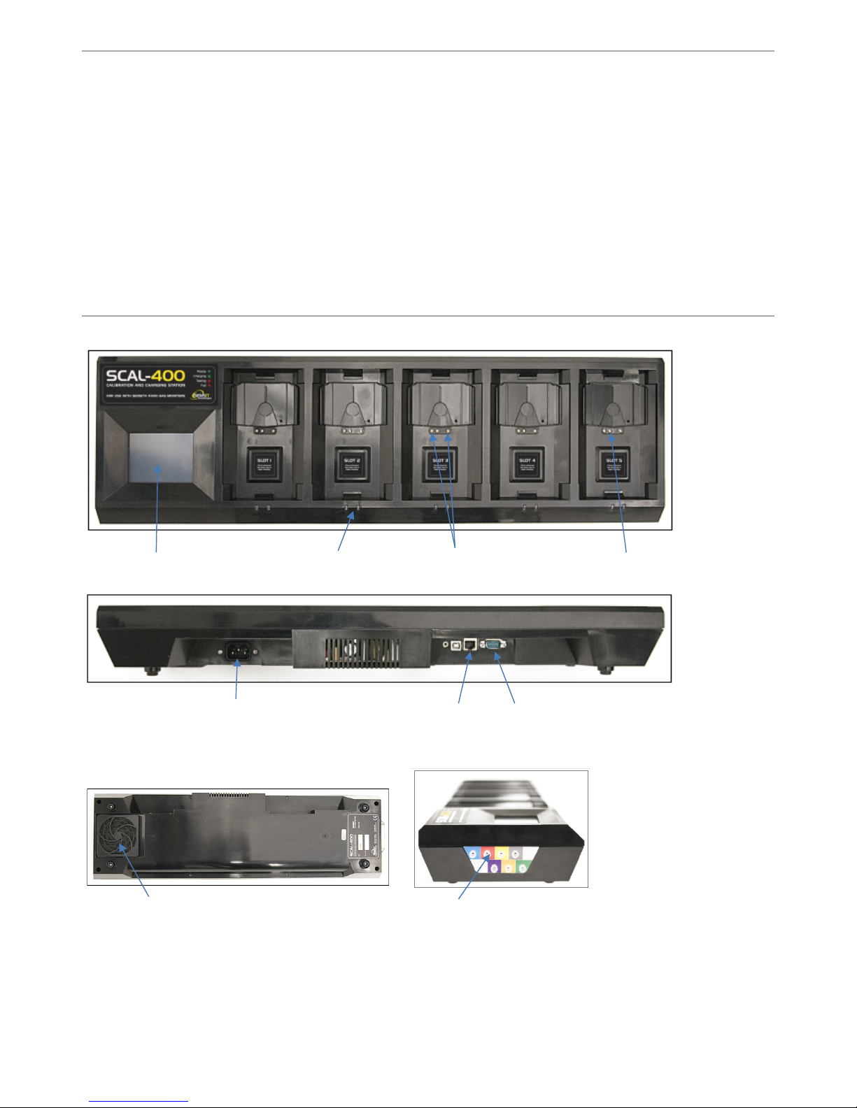
Features
Touchscreendisplay LEDstatusindicatorsChargingpinsCommunicationpin
Powerconnection RJ45Serial
Connections
CoolingfanintakeGasinlets/connections
4
What’s Included:
SCAL-400
Power Cord (120 VAC)
Instrucon Manual
SCAL-D Soware
USB Cable

5
4 / 12
Description
TheSCal‐400isamulti‐unitchargingandcalibrationstationforSensitP400gasdetectioninstruments.Itcanbumptestand/or
calibrateuptofiveP400unitsconsecutivelywhilesimultaneouslyrechargingthebatterypacks.TheSCal‐400alsodetectsifa
P400requirescalibrationorabumptestwhenconnectedandautomaticallyperformstherequiredtest.Duringconnection
anymanuallyperformedcalibrationandbumptestsintheinstrumentmemorylogwillautomaticallytransferfromP400to
SCal‐400.DatamanagementfortheSCal‐400requireseitherSCal‐DorSCal‐Nsoftwarepackages.AllSCal‐400stationscome
standardwithSCal‐Dsoftwarefordesktopapplication.
Thelocationtoplaceanyinstrumentisreferredtoasa“slot”.Foreachslottherearechargerandcommunicationconnections
aswellasLEDstoindicatethestatus.Alltestingfunctionsrequirenouserinteraction.
Thedisplayisatouchscreen.Instrumentandstationinformationcanbeaccessedbyusingyourfingerortheincludedstylus.
TheSCal‐400scanseachslot,updatestheLEDstatus,andrefreshesthedisplayscreenforeachsloteverythreeseconds.During
communication,theSCal‐400completesanylogtransferbeforescanninganotherslot.
LED Status
EachslothastwoLEDsindicatingthestatusforthedockedinstrument.ThefollowingtabledescribesthevariousLEDstates:
SCal‐400IndividualSlotLEDStatus:
GreenLEDRedLEDDescription
1OFFOFFNothingonslot
2ONOFFReady(alltestdone,fullycharged/alkalineOK)
3OFFONFailcalibration/bumptest/alkalinelowbattery
4BLINKON/OFF/BLINKCharging
5ON/BLINKBLINKTestinprogress/pending

6
5 / 12
Main Screen
WhentheSCal‐400ispoweredonbyconnectingittoa100‐240VACsupply,thedisplaywillshowtheMainScreen(refertothe
sampleshownbelow).Thisscreenisdividedinsixcells.Fiveofthecellsareforthefiveinstrumentslotsandonecellisfor
showingSCal‐400information.ThebackgroundcolorofaslotindicatesthestatusoftheP400inthecorrespondingslot(See
Table1).TappingtheslotthathasaunitdockedwillactivatetheDetailStatusScreen.Tappingthebluesectionwilltakeyouto
theMainScreenonlyifnounittestispendingorinprogress.
SampleimageoftheMainScreen:
Table1:MainScreenbackgroundcolorsanddescriptions
SlotScreen
BackgroundcolorStatusDescription
GRAYEmptyslot(Instrumentisnotdocked)
WHITE
OneofthefollowingTasks InProgress
Detectedunitandacquiringmoreinformation
Wakingupunit
DATATRANSFER–UpdateP400RTC,transfer
BUMP/CALLogfromInstrumenttoSCal‐400
Calibrationinprogress
Bumptestinprogress
Waitinginqueue
Charging
RED
Oneofthefollowingfailuresoccurred
Calibrationfailed
Bumptestfailed
Alkalinelowbatteryisdetected
GREENUnitisreadyforuse.
BLUETappingthissectionwillopentheMainMenuScreenonlyifno
unittestispendingorinprogress

7
6 / 12
Detail Status Screen
TheDetailStatusScreenprovidesadditional
detailsabouttheP400intheselectedslot.This
providesrealtimeprogressofdatatransfer,
calibrationandbumptest.Fromhereyoucan
manuallyperformacalibrationorbumptestby
tappingtheappropriateicon.
Table2referencesthedisplayedexample.
SampleimageoftheDetailStatusScreen:
Table2:DetailStatusScreendescription
LabelTypeBackground
Color
StatusDescription
1. Header
WHITEWAKINGUP/DATATRANSFERRED/TESTPENDING/WAITINGINQUEUE/IN
PROGRESS
REDFAILEDBUMPTESTORCALIBRATION
GREEN ALLTESTSUCCESSFULLYCOMPLETED
2. Battery
WHITECHARGING
REDALKALINE:LOWBATTERY
GREEN CHARGED/ALKALINE:OK
3. Data
Transfer
GRAYPENDING
WHITEUPDATINGRTC/DOWNLOADINGCALIBRATIONLOG/DOWNLOADINGBUMP
TESTLOG
GREEN COMPLETEDDATATRANSFER
4. Unit
Autozero
GRAYNOTREQUIRED
WHITEPENDING/PURGING/INPROGRESS
REDFAILED
GREEN PASSED
5. Sensor
Autozero
GRAYPENDING
REDFAILED
GREEN PASSED
6. Unit
Calibration
GRAYNOTREQUIRED
WHITEPENDING/PURGING/INPROGRESS
–
DISPLAYSADCCOUNTSOFSENSORBEING
CALIBRATED
REDFAILED
GREEN PASSED
7. Sensor
Calibration
GRAYPENDING
WHITEINPROGRESS
YELLOWCALIBRATIONGASSUPPLYTESTFAILED
REDFAILED
GREEN PASSED
8. UnitBump
Test
GRAYNOTREQUIRED
WHITEPENDING/PURGING/INPROGRESS
REDFAILED
GREEN PASSED
9. Sensor
BumpTest
GRAYPENDING
WHITEINPROGRESS
YELLOWCALIBRATIONGASSUPPLYTESTFAILED
REDFAILED
GREEN PASSED

8
7 / 12
Main Menu Screen
TheMainMenuScreenprovidesanoverviewofthesystem(Serial#,SoftwareRev#,DateandTime,ValveConfiguration).Italso
providesaccesstoviewcalibrationgasinformation,viewlogs,updatesettingsthroughtheSupervisorMenu,andaTestMenu.
TheValveSetupOverviewprovidesinformationaboutwhichgasinlets(valves)areconfiguredforeachcalibrationgas.
Eachlureinletonthemanifoldiscolorcodedwithlabelaroundit.
TheSupervisorandTestMenuscreensarepasswordprotected.
Calibration Gas Information Screen
Thisscreenisdividedineightcells.Eachcellrepresentsasinglegasinlet(valve).Thebackgroundcolorsandgasinletsarecolor
codedandmatchedforeasyidentification.Thecolorsonthemanifoldlabelcorrespondtothecolorsshownonthisscreen.It
alsoprovidestheinformationabouttypeofregulatorrequiredforthegasbottleandtheexpirationdateofthecalibrationgas.A
blank/emptycellindicatesthatparticulargasinlet(valve)isnotconfiguredandwillnotbeused.“N/A”inacellindicatesthat
thevalveisnotinstalled.Tappingonaconfiguredcell(i.e.‐notblank/empty)willtakeyouthepasswordscreen.Uponproviding
thecorrectpassword,thecalibrationgasinformationwillbedisplayed.
SampleimageoftheMainScreen:
SampleimageoftheCalibrationGasInformationScreen:

9
8 / 12
Log Review Screen
Thisscreenletsyoureviewallthelogsavailableinthe
SCal‐400slocaldatabase.Itwilldisplaythemost
recentlogfirst,butotherlogscanbeviewedbyusing
the“PREV”and“NEXT”buttons.NOTE:youcannotsee
logsfromotherstationsorSCal‐N/Ddatabases.
Table3referencesthedisplayedexample.
Password Screen
ThePasswordScreenprovidesasupervisorlevelofprotectiontoaccess
theSupervisorandTestMenusandthemenutoupdatethecalibration
gasinformation.Thepasswordisfournumberslong.Tappingthe
“CLEAR”buttonwillresettheboxes,allowingyoutotryagain.Afteryou
enterfournumbers,thepasswordwillautomaticallybechecked.Upon
providingthecorrectpassword,thenextscreenwillbedisplayed.
Enteringanincorrectpasswordwillchangethescreentitletobe
displayedas“WRONGPASSWORD”inred.Afterthreeunsuccessful
attempts,thepasswordscreenwillcloseandyouwillreturntothe
previousscreen.
SampleimageoftheLogReviewScreen:
Table3:LogReviewScreenbackgroundcolorsanddescriptions
TypeBackground
Color
Description
Serial#NADisplaystheserial number oftheP400unit
TypeNADisplaysthe type oflog:BUMP/CAL
ResultBar
Resultbarisdividedin5cells.Eachcellrepresentssensorcalibration/bumpresult.
RED
FAILED:BUMPFAILED
CALFAILED:CALIBRATIONFAILED
ZEROFAILED
YELLOWCALGASFAILED:Calibrationgassupplycheckfailed
GRAYSensorTest(calibration/bump)isskippedbyuser
GREENPASSED
SampleimageofthePasswordScreen:

10
Supervisor Menu Screen:
ThesettingsoftheSCal‐400canbechangedfromwithintheSupervisorMenu.
PleaseseeTable4foralistofalltheconfigurableitemsthatcanbemodified.You
canusetheverticalscrollbartoviewallavailableoptions.Scrolltoandtapthe
buttonforthesettingyouwouldliketochange.Anotherscreenwillappearthat
willallowyoutoview/adjustthecurrentsetting.
Table4:SupervisorMenuItems
1SETTIMEZONE
Thisallows youtosetthetimezoneoftheclock. Updatingthissettingwill
restarttheSCal‐400application.Allavailabletimezoneswillbelisted.Select
theappropriatetimezoneandclick“UPDATE”.Amessageboxwillbe
displayedtoindicatesystemwillrestart.Click“OK”tocontinue.
2SETCLOCK
Thisallows youtochangethedate andtime oftheclock.
SelectValueScreen:
Theheaderofthisscreenwilldisplaythenameofthesettingyou
arechanging.“LL”and“UL”inthesampleimagewillbereplacedby
thelowerlimitandupperlimitnumbersfortheselectedsetting.
Clickthe“ACCEPT”buttontoupdatethevalue.
Enable/DisableScreen:
Theheaderofthisscreenwilldisplaythenameofthesettingyou
arechanging.Thisscreenallowsyoutoenableordisablethe
selectedfeature.Clickthe“ACCEPT”buttontoupdatethevalue.

11
10 / 12
3SETCHARGINGOFFSET
Thisoptionallows thefactorytoadjusttheoffsetforrecharging.Itwill
displaythecurrentADCreadingforeachslotandalsothecurrentlysaved
offset.Click“UPDATE”tosaveanewoffsetreading.Beforeupdatingthis
setting,pleaseremoveallP400unitsfromallslotsandwaitfewsecondsfor
thereadingstostabilize.
Pleasecontactfactorybeforechangingthissetting.
4SCAL/LANSETTINGS
Thiswillallowyoutoset thenecessarynetwork informationtoenablethis
devicetocommunicatewithSCal‐N.
5BACKUP/RESTOREDB
a. AUTOBACKUP:
Thisoptionallowsasupervisortosetupautomaticbackupsofthe
databasetoaninternalmemorycard.Enablingthisoptionwill
requireamemorycardtobepresent.Acopyofthedatabasewillbe
savedtothememorycardeveryday.Theautomaticallysaved
backupfilesarenamedAUTO_DDMMYYYY.sdf.
b. BACKUPDATABASE:
Thisoptionwillcreateamanualbackuponthememorycard.These
backupdatabasesarenamedMANUAL_DDMMMYYYY.sdf.
c. RESTOREDATABASE:
Thiswillallowtheusertorestoreadatabasebackfromthememory
card.Itwilldisplayalistofallavailablebackupdatabases(both
manualandautomatic)thatexistonthememorycard.Youcan
chooseonedatabaseandclick“SELECT”torestoreit.
6BUMPAFTERCALTurningthisoptionon willmaketheunittogothroughthebumptestafter
calibrationisperformedsuccessfully.
7BUMPONDOCKTurningthisoptionon willmaketheunittogothroughthebumptestevery
timeyoudocktheunit.
8VALVECONFIGURATIONThisallows youtoselecttypeofcalibrationgasconnectedtotheselectedgas
inlet(valve)alongwithregulatortype.

12
11 / 12
Valveconfigurationscreen:
Themiddlesectionofthisscreenisdividedineightcells.Eachcellrepresentsasinglegasinlet(valve).The
backgroundcolorsandgasinletsarecolorcodedandmatchedforeasyidentification.Thecolorsonthe
manifoldlabelcorrespondtothecolorsshownonthisscreen.Italsoprovidestheinformationaboutthetype
ofregulatorrequiredforthegasbottleandtheexpirationdateofthecalibrationgas.Ablank/emptycell
indicatesthatparticulargasinletisnotconfiguredandwillnotbeused.“N/A”inacellindicatesthatthe
valveisnotinstalled.TappingonanyofthecellswilltakeyoutoValveConfigurationModificationScreen.
ValveConfigurationModificationScreen:
Thisscreenprovidesyouwithanoptiontoconfigurethecalibrationgasfortheselectedgasinlet(valve).You
canalsochoosewhichregulatortypetouse.Ifademandregulatorisused,theinternalpumpwillturnon
whileusingthatparticulargasinlet(valve).Ifyouwanttodisabletheselectedgasinlet(valve),thenselect
“NONE”asthegastype.Allofthecalibrationgasesthatareconfiguredfortheotherinlets(valves)willbe
disabledinthisscreen.Ifyouwanttoswitchagastoadifferentinlet(valve),youneedtodisablethat
particularcalibrationgasfromtheinlet(valve)beforeenablingitonthedesiredinlet(valve).
9RESETVALVECONFIG
Resetthevalveconfigurationtothefactorydefaultasperfollowing:
GREEN–AIR–DEMANDREGULATOR
GRAY–QUAD–DEMANDREGULATOR
10ERASELOGThiswillerasetheentirelogsavedinthelocaldatabase.
11PURGETIMEBEFOREAmountoftime(inseconds)theunitwillpurgethelinewithairbefore
startinganycalibration/bumptest.
12PURGETIMEAFTERAmountoftime(inseconds)the unitwillpurgethelinewithairafterit
completesacalibration/bumptest.
13SPECIALITYGASPURGE
Amountoftime(inseconds)the unitwillpurgethelinewithairbefore
startinganycalibration/bumptestforaspecialtygassensor(otherthanO2,
EX,CO,H2S).
14CALGASCHECKTIME
Amountoftime(inseconds)theSCal‐400 willwaitafteropeningthe
calibrationgasvalveandbeforecheckingforanemptycylinder.
Pleasecontactfactorybeforechangingthissetting.
15PRESSURETHRESHOLD
Minimumdifferenceofthepressuresensorresponse(inADCcounts)
requiredtoverifythecalibrationgasbottleisnotempty.Thissettingisonly
validwhenthevalveisconfiguredtouseapressureregulator.
Pleasecontactfactorybeforechangingthissetting.
16VACUUMTHRESHOLD
Maximumdifferenceofthepressuresensorresponse(inADCcounts)
requiredtoverifythecalibrationgasbottleisnotempty.Thissettingisonly
validwhenthevalveisconfiguredtouseademandregulator.
Pleasecontactfactorybeforechangingthissetting.
17SETPASSWORDThisoptionwillallowasupervisortochoosetheirownpasswordotherthan
thedefaultpassword.
18FLIPSCREENThiswillflipthescreen180°.
19RESETSETTINGSThisoptionwillresetallsettingsbacktothefactorydefaults(exceptforthe
serialnumber).
20CLOSEAPPLICATIONThiswillclosetheapplicationandexittoWindows.
21SETSERIALNUMBERThiswillletyoumodifytheserialnumber oftheunit.Thisispassword
protectedandcanonlybemodifiedatthefactory.
22DONOTSAVE
Enablingthisoptionwillnotsave anybumporcalibrationlogstotheSCal‐400
database.Thisoptionisspeciallydesignedforfactoryusetoverifythe
SCal‐400isworkingproperlywithoutcreatinganylogs.Thisispassword
protectedandshouldonlybemodifiedatthefactory.

13
12 / 12
Operation – Setup:
1. LocatetheSCal‐400inanareathatisclean,dry,andinanareaknowntobefreeofcombustiblegases.
2. LaytheSCal‐400flat.Positioningthehousingatanangleinterfereswithpropergasflowtothe
instruments.
3. Attachthepowercordtotheinstrument(donotplugintothepowersourceyet).
4. Attachthepropergasbottlestotheinletsontheleftside.Thegraylocationispresetforquad‐gas
mixturesofLEL,CO,H2SandO2.
5. Attachahosetothegreeninlettobringfreshairforzeroing.Keeptheotherendofthehoseinclean
airandawayfromthestation.
6. Attachthecable(EthernetorUSB‐to‐RS232)forserialdataconnection(notrequiredforoperation).
ForoperationofSCal‐DorSCal‐Ndatamanagementsoftware,pleasereviewtheirrespective
instructionmanuals.
7. Turnonthegasifapressureregulatorisused.Demandregulatorsdonotrequirethisaction.
Operation – System Activation:
1. PlugtheSCal‐400intoapowersource.
2. ThescreenwillilluminatewithSensitlogo.
3. Theinternalfanwillstarttospin.Thisistocoolthepowersupplycomponents.
4. TheSCalapplicationwillautomaticallyinitiateandthenbereadytouse.
Operation – P400 Testing:
1. Removethepumpassemblyifattached.
2. Besuretheinstrumentfilteriscleananddry.
3. Laytheinstrumentfacedownintoanyslot.
4. Iftheinstrumentisoff,itwillturnonautomatically.
5. Theinstrumentwillbebumptestedand/orcalibratedasdeterminedbytheinstrumentsetup.
6. Theinstrumentwillrechargeifneeded.Alkalinepoweredinstrumentswillnotrecharge.Thestation
willindicateifthebatteryislowinanalkalinepoweredinstrument.
7. Batterychargingstatusindicatorswillfunction.
8. Fullrechargerequiresapproximately5.5hours.
9. Thedisplaywillupdatethestatusattheendofeachprocess.Redbackgroundsindicatefailures.
Tapthecorrespondingscreenlocationformoreinformation.
Warranty
Your Sensit SCal-400 is warranted to be free from defects in materials and workmanship for a period of two
years after purchase. If within the warranty period the instrument should become inoperative from such
defects the instrument will be repaired or replaced at our option. This warranty covers normal use and does not
cover damage which occurs in shipment or failure which results from alteration, tampering, accident, misuse,
abuse, neglect or improper maintenance. Proof of purchase may be required before warranty is rendered. Units
out of warranty will be repaired for a service charge. Internal repair or maintenance must be performed by a
Sensit Technologies authorized technician. Violation will void the warranty. Units must be returned postpaid,
insured and to the attention of the service department for warranty or repair.
This warranty gives you specific legal rights and you may have other rights which vary from state to state.

NOTES

NOTES

Warranty
Your Sensit SCal-400 is warranted to be free from defects in materials and workmanship for a period of two years
after purchase. If within the warranty period the instrument should become inoperative from such defects the
instrument will be repaired or replaced at our option. This warranty covers normal use and does not cover damage
which occurs in shipment or failure which results from alteration, tampering, accident, misuse, abuse, neglect or
improper maintenance. Proof of purchase may be required before warranty is rendered. Units out of warranty
will be repaired for a service charge. Internal repair or maintenance must be performed by a Sensit Technologies
authorized technician. Violation will void the warranty. Units must be returned postpaid, insured and to the attention
of the service department for warranty or repair.
This warranty gives you specic legal rights and you may have other rights which vary from state to state.
Sensit Technologies
851 Transport Drive
Valparaiso, Indiana
46383
USA
Tel: 219/465-2700
Fax: 219/465-2701
Email: [email protected]
Web: www.gasleaksensors.com
SCAL-400 INSTRUCTION MANUAL
Part # 750-00057 Revision 12-15-17
MADE IN THE USA
WITH GLOBALLY SOURCED COMPONENTS
Table of contents