Sentera Controls DSVCX-R Service manual
Other Sentera Controls Transmitter manuals
Sentera Controls
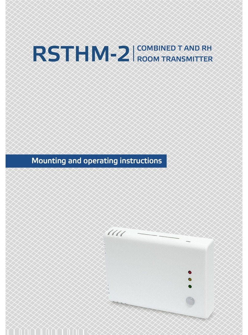
Sentera Controls RSTHM-2 Service manual

Sentera Controls
Sentera Controls RSMFH-2R Service manual
Sentera Controls
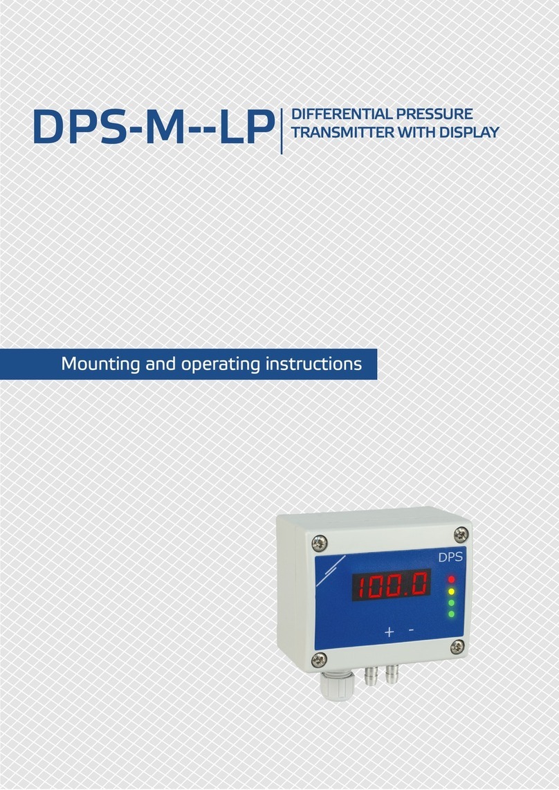
Sentera Controls DPS-M-LP Service manual
Sentera Controls
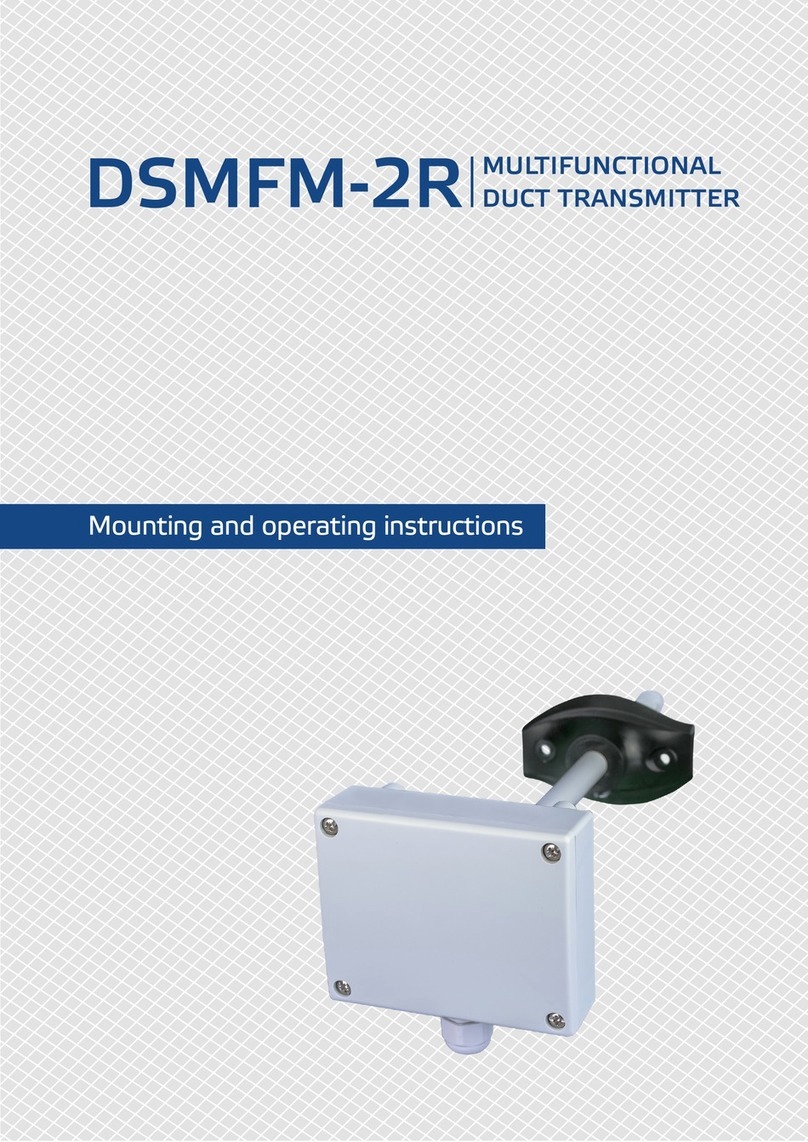
Sentera Controls DSMFM-2R Service manual
Sentera Controls
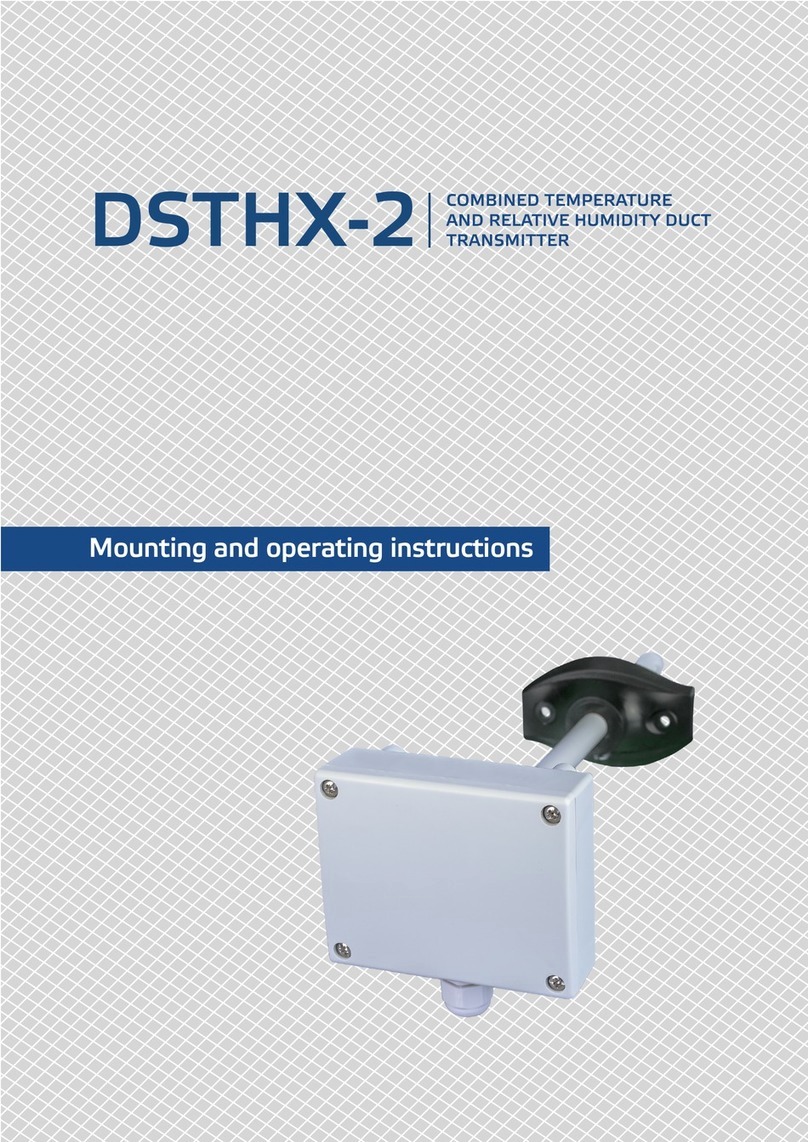
Sentera Controls DSTHG-2 Service manual
Sentera Controls
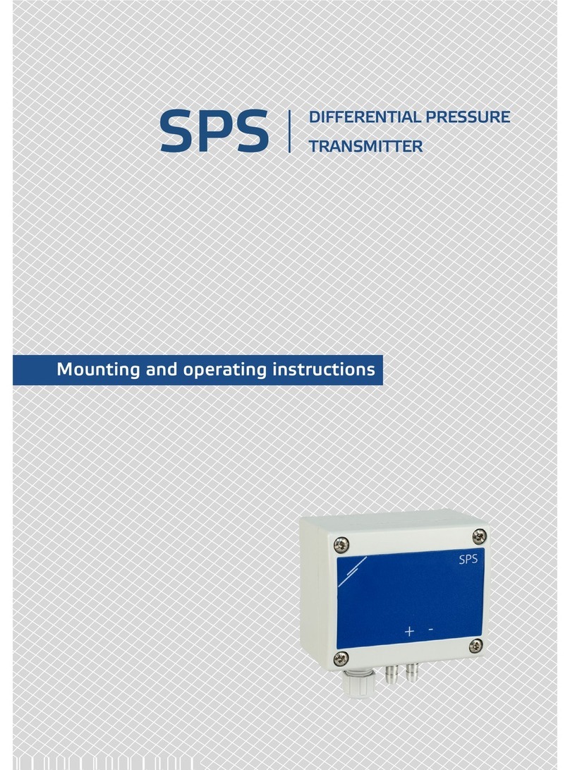
Sentera Controls SPS series Service manual
Sentera Controls
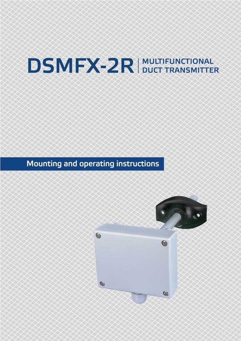
Sentera Controls DSMFX-2R Service manual
Sentera Controls
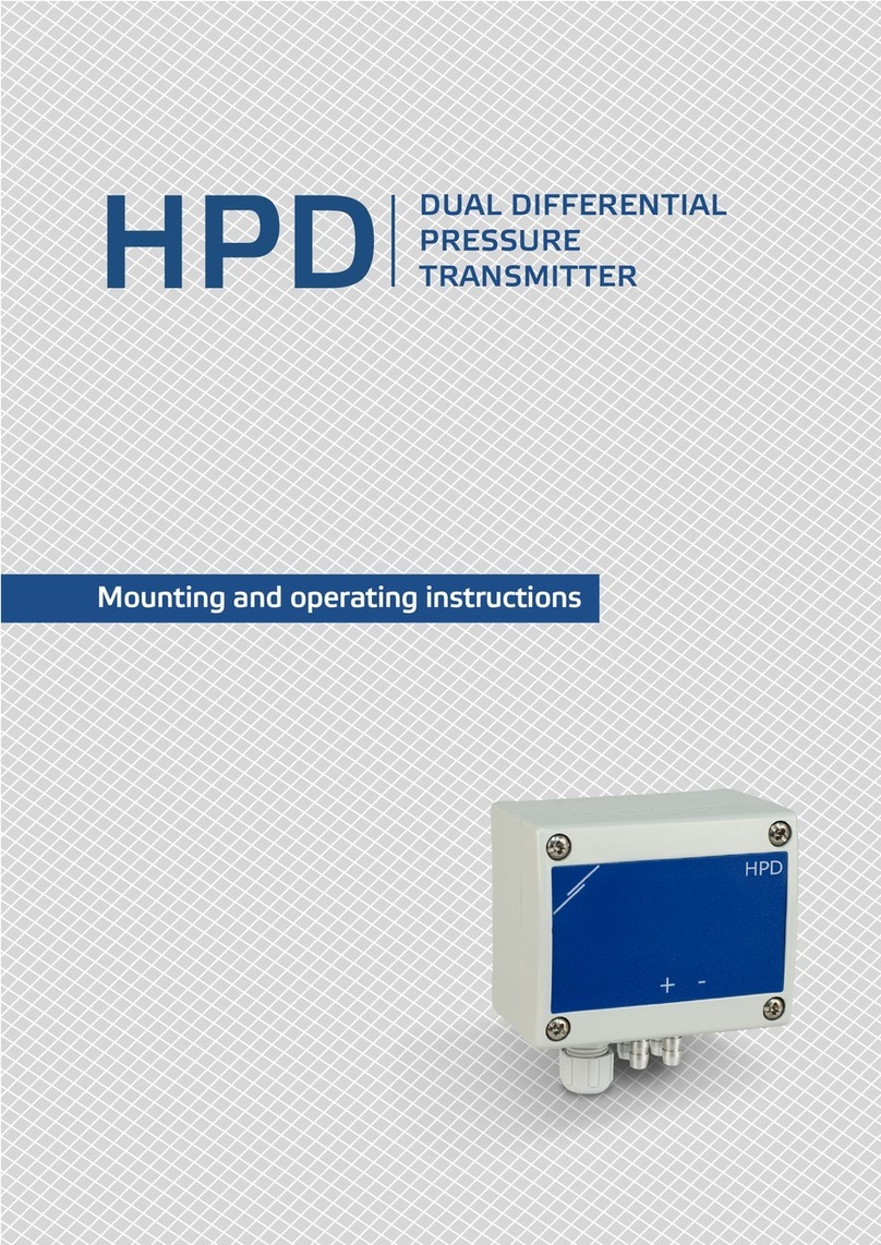
Sentera Controls HPD Service manual
Sentera Controls
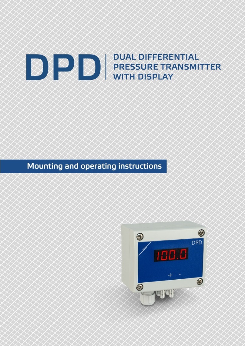
Sentera Controls DPD-F-1K0 Service manual
Sentera Controls
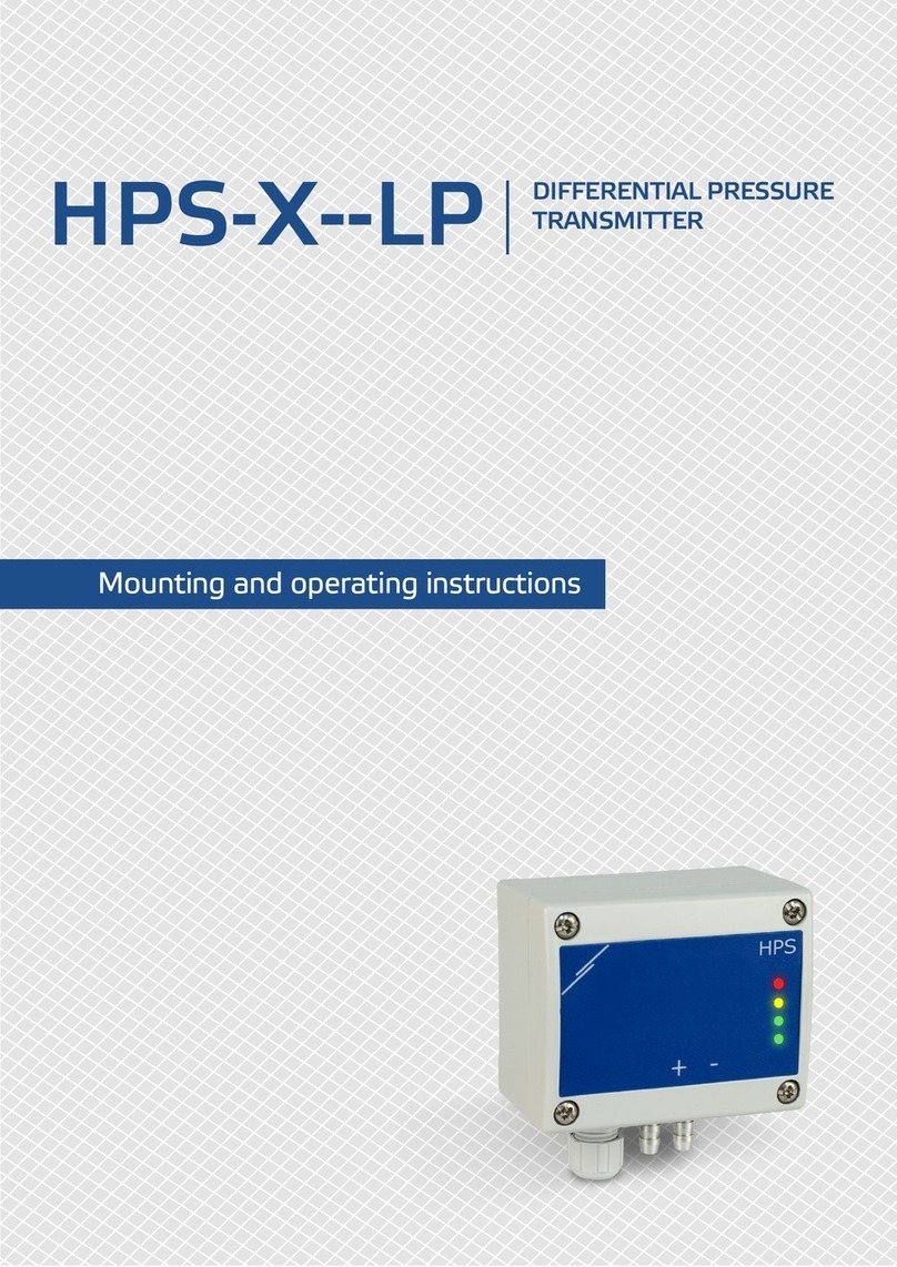
Sentera Controls HPS-X-LP Service manual
Sentera Controls
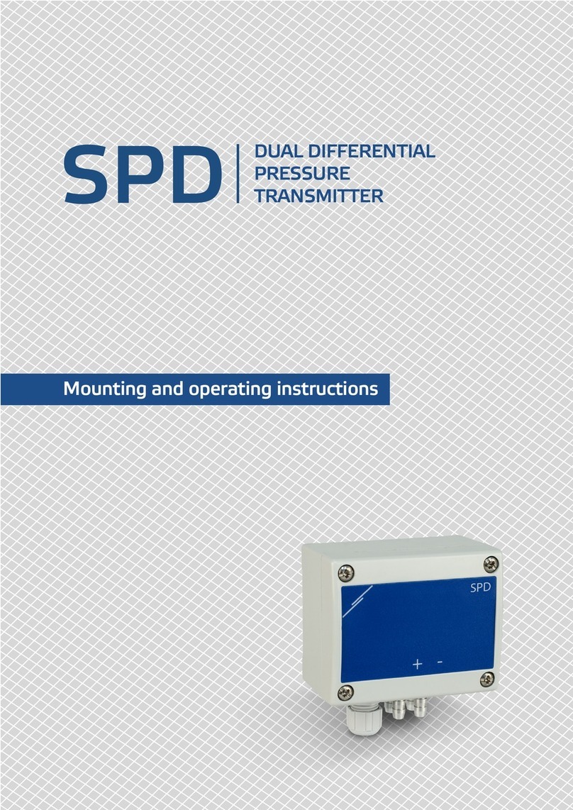
Sentera Controls SPD Service manual

Sentera Controls
Sentera Controls RSMFH-3 User manual
Sentera Controls
Sentera Controls RSTH 2 Series Service manual
Sentera Controls
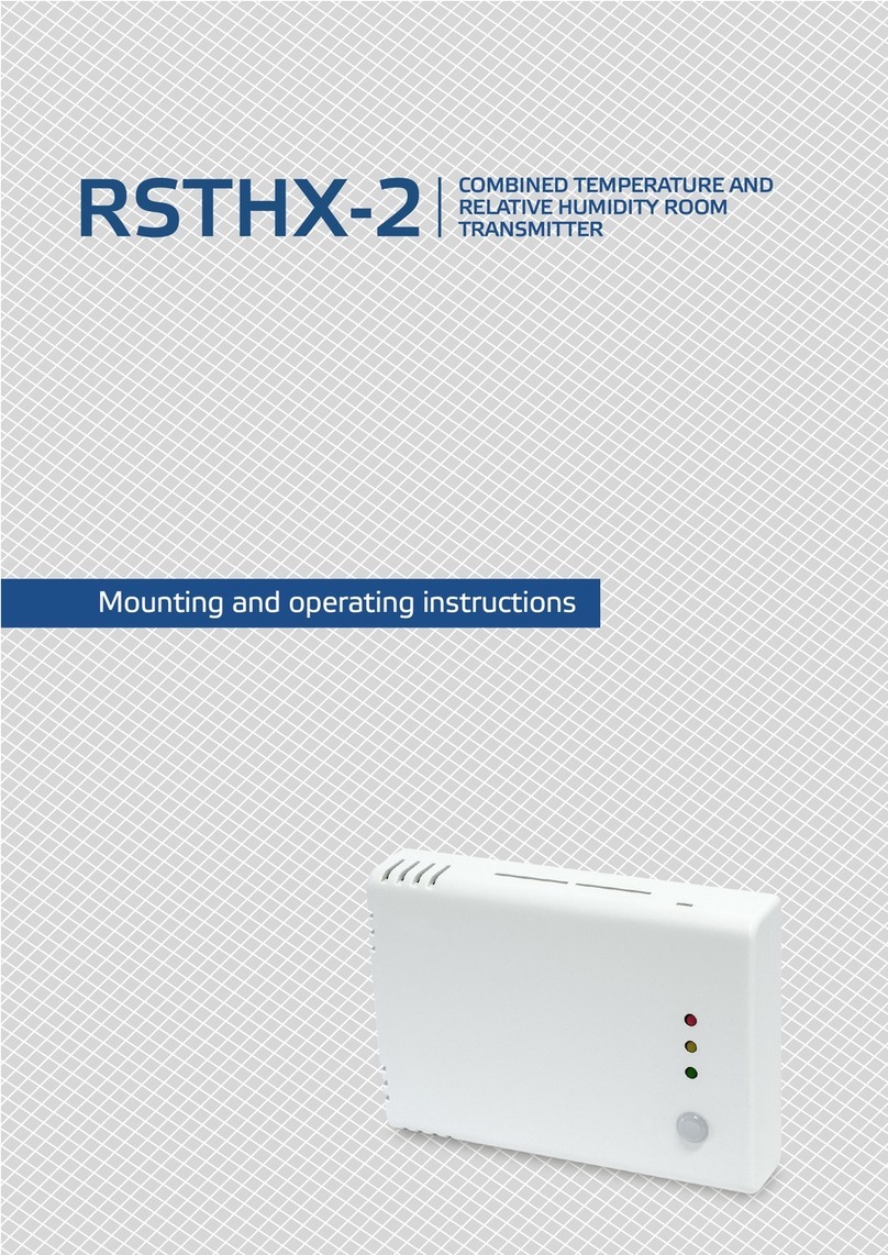
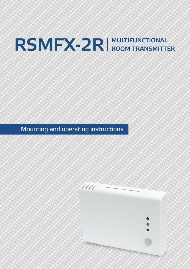
Sentera Controls RSTHX-2 Service manual
Sentera Controls
Sentera Controls RSMF-2R Series Service manual

Sentera Controls
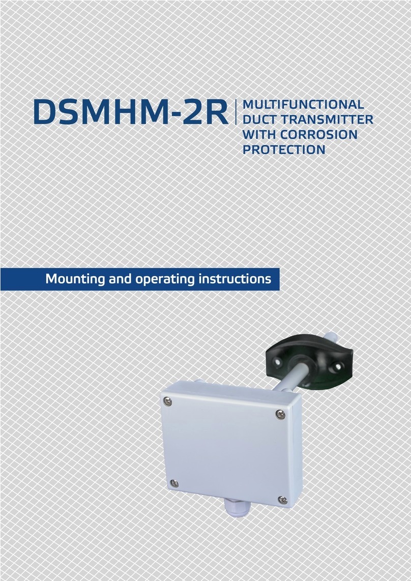
Sentera Controls HPS-X -2 Service manual
Sentera Controls
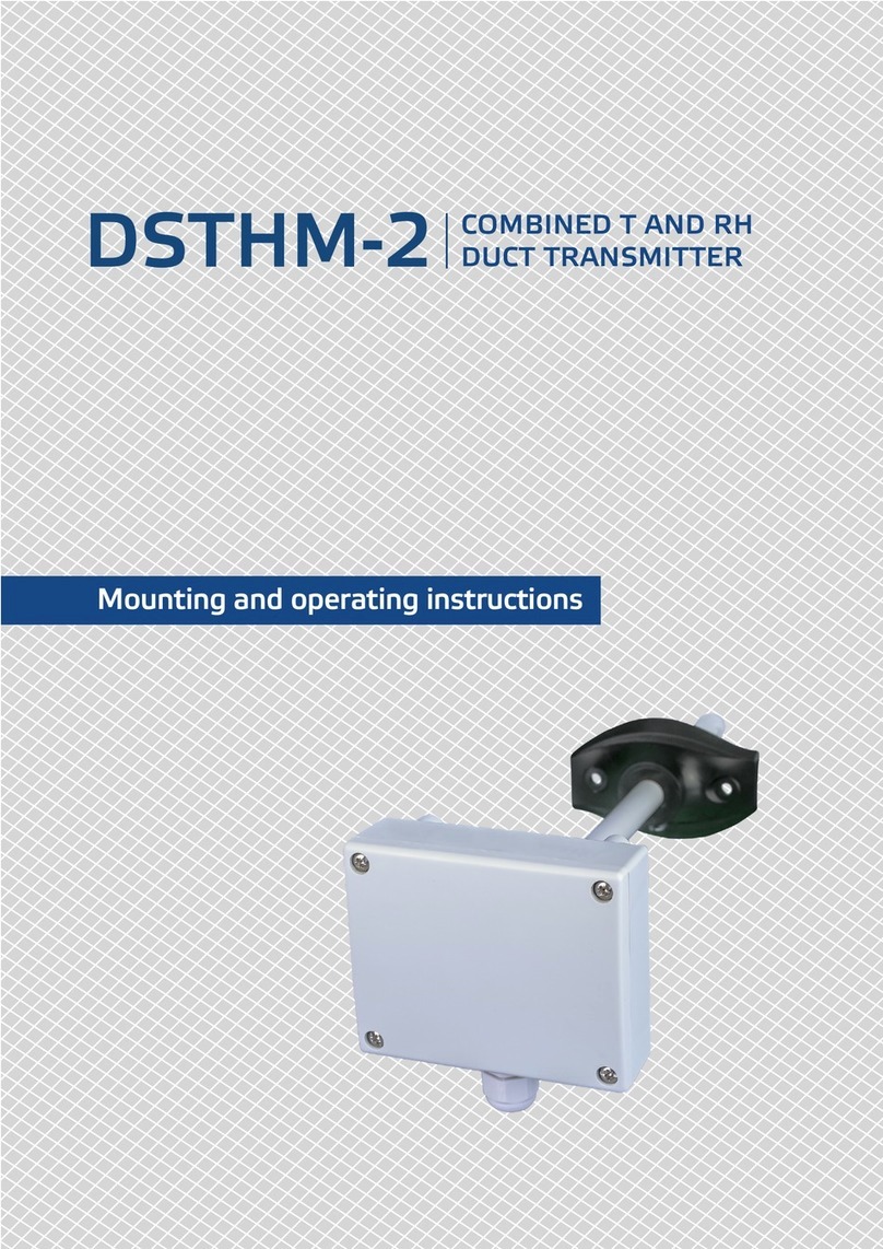
Sentera Controls DSMHM-2R Service manual
Sentera Controls
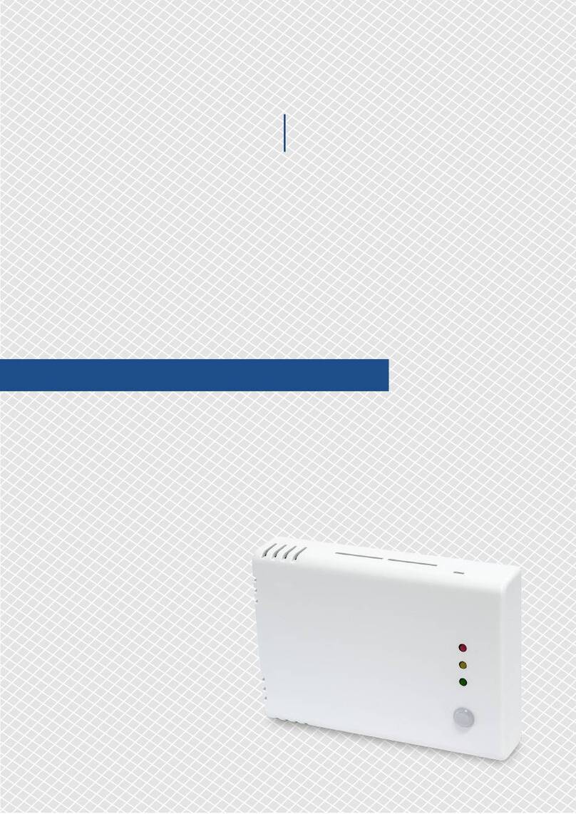
Sentera Controls DSTHM-2 Service manual
Sentera Controls
Sentera Controls RSMFX-3 Service manual
Popular Transmitter manuals by other brands

Geo
Geo Web Pack quick start guide

Inovonics
Inovonics EchoStream EN1210W installation instructions

IKONNIK
IKONNIK KA-6 quick start guide

Rohde & Schwarz
Rohde & Schwarz SR8000 Series System manual

Audio Technica
Audio Technica UniPak ATW-T93 Installation and operation

NIVELCO
NIVELCO EasyTREK SCA-300 Series Programming manual


