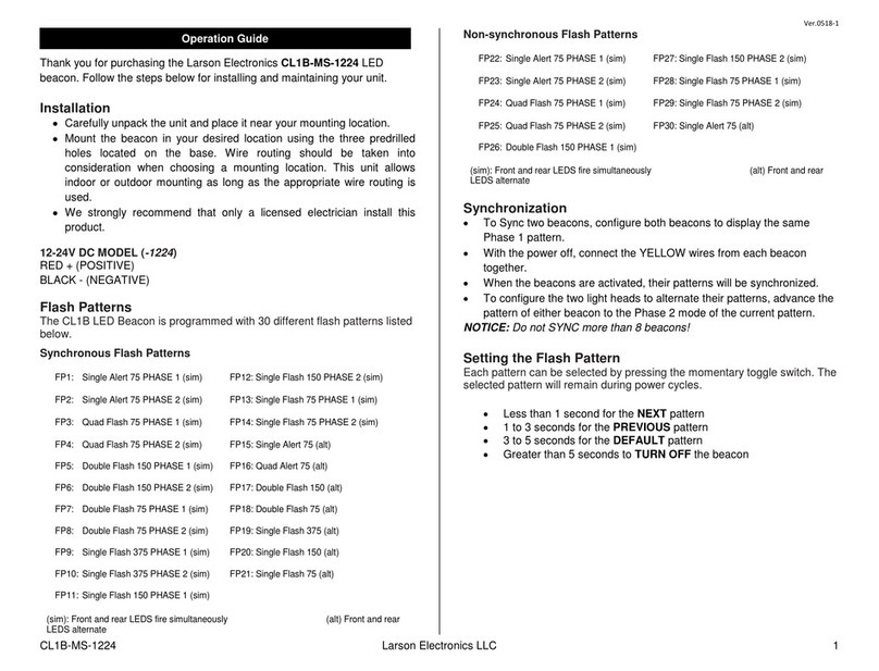
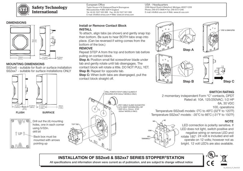
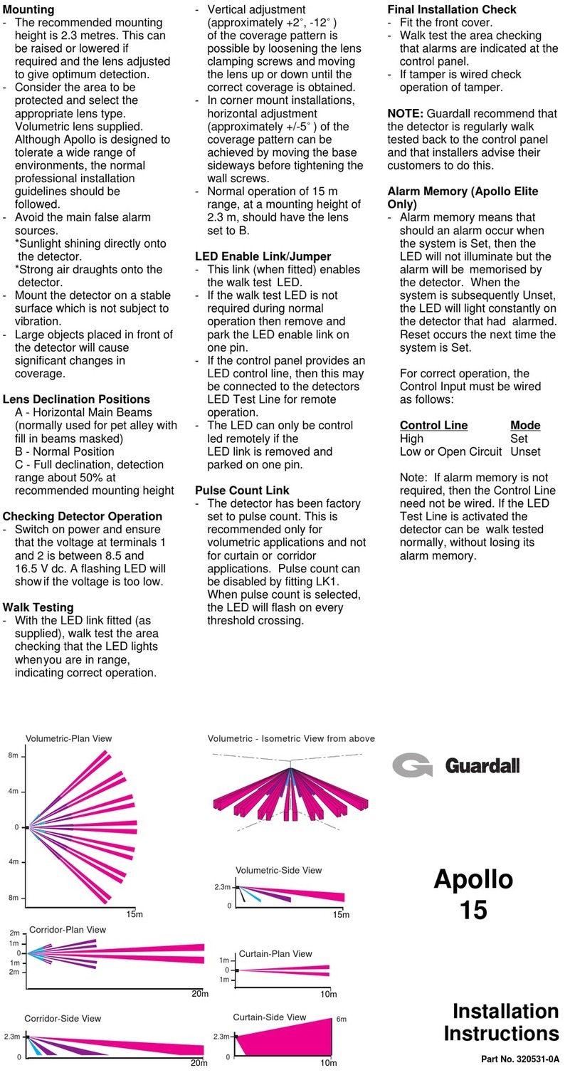
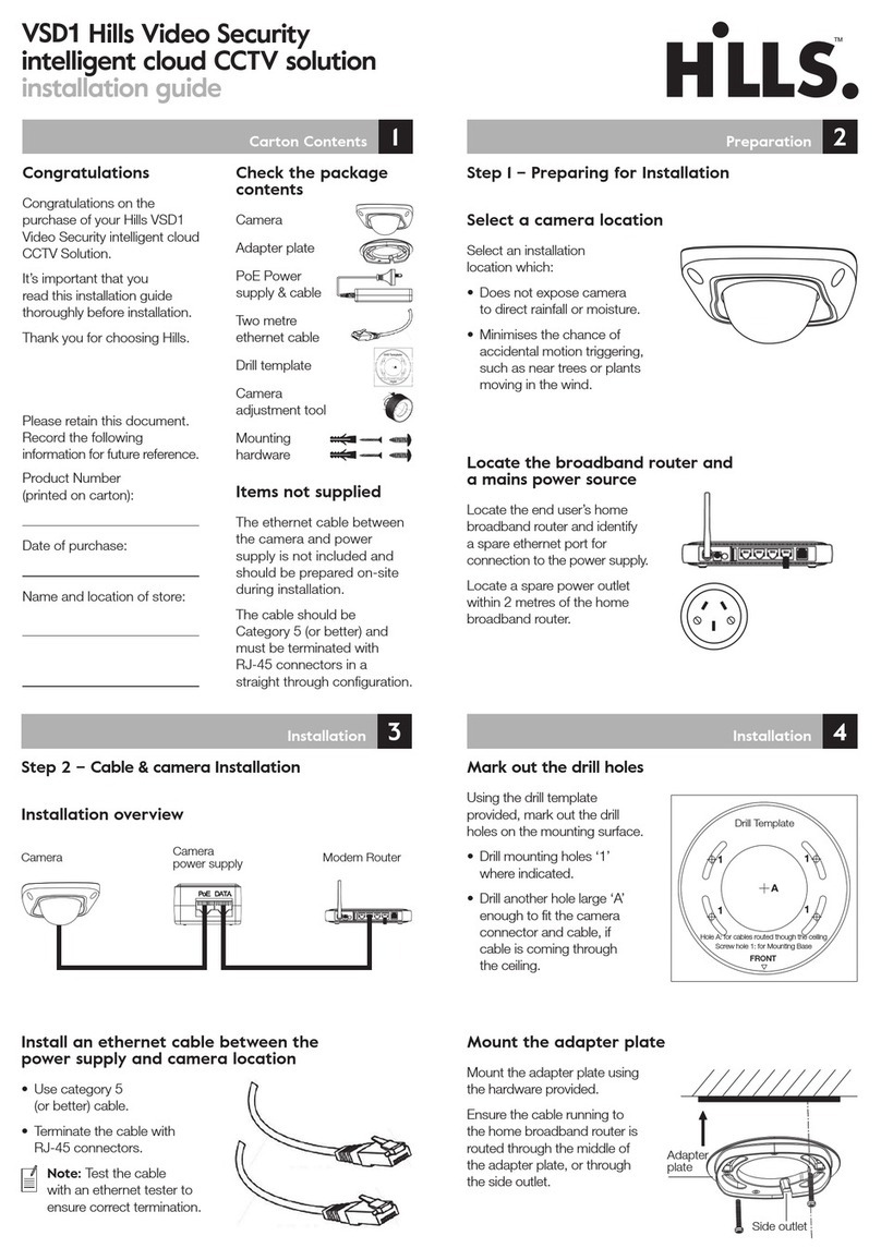
Sentryway CurveTrack User guide

CurveTrack®
System
Installation Guide
Install Guide P/N : 0309-0218-00
VIDEOSURVEILLANCE SYSTEMS
SENTRY
WAY
®
CT V2 001
SENTRYWAY
Les Carrés du Parc
10 rue des Rosiéristes
69410 Champagne au Mont d’Or


VIDEOSURVEILLANCE SYSTEMS
SENTRY
WAY
®
CT V2 001
Page 3 of 70
System Installation Guide
CurveTrack®
System
Installation Guide
Installation Guide Revision Status :
Rev. Description of Change Date Approval
Sentryway - Les carrés du Parc - 10 rue des Rosiéristes - 69410 Champagne-au-Mont-d’Or
Phone : 06 64 78 59 57 - Website : www.sentryway.com
e CurveTrack® is a product of Sentryway, and is protected patents.
is document discloses information proprietary to Sentryway, and no intent to abandon such proprietary
information or to grant any rights to the recipient, is to be inferred from any transfer of this document. All
transfers of this document, except where express written consent has been granted, are made subject to the
conditions that the document not be reproduced, copied, or otherwise represented either in whole or in part,
and that no part of its contents or any embodiment thereof will be divulged or used in connection with any
matters other than for Sentryway
STATEMENT OF CONFIDENTIALITY

VIDEOSURVEILLANCE SYSTEMS
SENTRY
WAY
®
CT V2 001
Page 4 of 70
System Installation Guide
CAUTION
It is essential that safety precautions noted throughout this manual be followed
along with OSHA Safety Standards and local electrical codes at the installation
site. To prevent personal injury, use the safety equipment specied in the
Recommended Tool list elsewhere in this manual.
SENTRYWAY reserves the right to modify the contents of this manual at any
time. Sentryway shall not be held liable for errors contained herein or for inci-
dental or consequential damages in connection with furnishing, performance,
or the use of material in this manual.
NOTICE TO USERS

VIDEOSURVEILLANCE SYSTEMS
SENTRY
WAY
®
CT V2 001
Page 5 of 70
System Installation Guide
Table of Contents
1. INTRODUCTION...............................................................................................................7
1.1 Explanation of Symbols.............................................................................................................................8
1.2 Technical Specications............................................................................................................................9
1.2.1 Physical Dimensions of the camera carriage..........................................................................................10
1.3 Units of measure.........................................................................................................................................10
1.4 General safety precautions.........................................................................................................................10
1.5 Responsibilities of the Installer.................................................................................................................11
2. IDENTIFICATION OF MAJOR
COMPONENTS...............................................................12
2.1 System Components...................................................................................................................................12
2.2 Rail Components........................................................................................................................................14
2.3 Carriage Components................................................................................................................................17
2.4 Power supply assembly (power end cap) Components..............................................................................18
3. SITE EVALUATION AND
PLANNING...............................................................................19
3.1 Overview.....................................................................................................................................................23
3.2 Setting Up A Schedule................................................................................................................................21
3.3 Planning Installation of the System Run...................................................................................................21
3.4 Material Inspection and Inventory............................................................................................................22
3.5 Material Storage.........................................................................................................................................22
3.6 Recommended Tool
List
.............................................................................................................................23
4. SUPPORT STRUCTURE INSTALLATION........................................................................24
4.1 General.......................................................................................................................................................24
4.2 Fastening Support Hardware to Bar
Joists—Perpendicular
.....................................................................24
4.3 Fastening Support Hardware to Bar
Joists—Parallel
................................................................................25
4.4 Fastening Support Hardware to Steel Beams—Perpendicular.................................................................26
4.5 Fastening Support Hardware to Steel
Beams—Parallel
............................................................................27
4.6 Fastening Support Hardware to C–Purlin
Beams—Perpendicular
..........................................................28
4.7 Fastening Support Hardware to C–Purlin Beams—Parallel....................................................................30
4.8 Fastening Support Hardware to Flush Concrete–Parallel and Perpendicular.........................................31
4.9 Fastening Support Hardware to Reinforced Concrete
Beams
..................................................................33
5. THREADED ROD INSTALLATION..................................................................................34
5.1 General.......................................................................................................................................................34
5.2 Cutting the readed Rod.........................................................................................................................34
5.3 Installing readed Rod in Channel for Parallel Runs............................................................................36
5.4 Installing Turnbuckles on readed Rods...............................................................................................38
6. RAIL SECTION
INSTALLATION.......................................................................................40
6.1 Rail Section Inspection..............................................................................................................................40
6.2 Rail Section Cleaning.................................................................................................................................40
6.3 Rail Section Preparation............................................................................................................................40

VIDEOSURVEILLANCE SYSTEMS
SENTRY
WAY
®
CT V2 001
Page 6 of 70
System Installation Guide
6.4 Connecting rail Sections to readed Rod Assemblies–Method 1..........................................................42
6.5 Connecting rail Sections to readed Rod Assemblies–Method 2..........................................................43
6.6 Alignment of System Run..........................................................................................................................43
6.7 Guy Wire Suspension.................................................................................................................................51
7. INSTALLATION OF COPPER CONDUCTORS............................................................53
7.1 General.......................................................................................................................................................53
7.2 Soldering copper conductors....................................................................................................................54
7.3 Inserting conductors into plastic track.....................................................................................................58
8. INSTALLATION OF BUMPERS STOP BRACKETS
........................................................59
8.1 General.......................................................................................................................................................59
8.2 Installation.................................................................................................................................................59
9. INSTALLATION OF RF ADAPTER AND TERMINATOR BOARDS
............................60
9.1 RF Adapter PCB Installation....................................................................................................................60
9.2 Terminator Board Installation..................................................................................................................60
10. INSTALLATION OF LIMIT SWITCH ACTUATORS....................................................61
10.1 General....................................................................................................................................................61
10.2 Installing limit switch actuators.............................................................................................................61
11. SYSTEM CABLING WITH POWER END CAP ASSEMBLY.........................................66
12. INSTALLING THE CARRIAGE.....................................................................................63
12.1 Carriage inspection.................................................................................................................................63
12.2 Installing the carriage in the system run................................................................................................63
12.3 Inspecting the system run.......................................................................................................................64
13. SYSTEM INITIALIZATION AND POWERING UP.......................................................65
13.1 Power up / Initialization.........................................................................................................................65
13.2 Programming instructions....................................................................................................................65
14. WINDOWS.....................................................................................................................66
14.1 General description.................................................................................................................................66
14.2 Windows installation on straight rails...................................................................................................66
14.3 Windows installation on curved section of rail.....................................................................................68
15. FIELD REPLACEABLE PARTS LIST..............................................................................69

VIDEOSURVEILLANCE SYSTEMS
SENTRY
WAY
®
CT V2 001
Page 7 of 70
System Installation Guide
1. Introduction
Sentryway has designed and built this state-of-the-art Closed Circuit Television (CCTV) Traveling Camera
System using the nest materials and components available. e CurveTrack® consists of a CCTV camera, with
pan, tilt, and zoom capability, which moves along a rail on a carriage concealed from view within a transparent,
mirrored enclosure. e carriage is not tethered to any power or video cables. Because the camera moves on a
rail, line-of-sight and blind spot issues are eliminated and total coverage can be achieved using fewer cameras.
e CurveTrack® camera provides a continuous, high resolution, real-time, moving video picture while
remaining hidden. e system can be operated in automatic or manual modes. An on-site system operator can
easily tilt, pan, zoom, and focus the camera to monitor specic areas and follow activity.
Of primary importance is the fact that individual CurveTrack® systems can be accessed remotely via the
internet. is capability enables, for instance, corporate headquarter’s personnel to observe and monitor on-
going operations at multiple facilities in real time. Management can maintain total control over display, pricing,
and stocking of merchandise while ensuring compliance with all operational directives and procedures.
e instructions presented in this manual are intended for technicians and comprise the recommended
installation procedures for all components of the CurveTrack® system. Operating instructions for the system
are contained in a separate User’s Manual available from Sentryway
Quiet, long lasting, trouble – free operation of the CurveTrack® system is dependent upon proper installation of
all components. It is imperative that installation technicians read and understand this manual thoroughly before
beginning an installation. Installers must use good judgment when slight deviations from these instructions
are called for.

VIDEOSURVEILLANCE SYSTEMS
SENTRY
WAY
®
CT V2 001
Page 8 of 70
System Installation Guide
1.1 Explanation of symbols
e Exclamation Mark is used as a general safety alert. Read and follow instructions carefully when
this symbol appears.
A Note is a specic fact or time– saving tip that, if not followed, could aect the performance of the associated
procedure.
A Caution is present when failure to properly perform a particular action or procedure could cause serious
equipment damage or cost considerable time to correct. Complying with a Caution can help to prevent serious
trouble.
A Danger statement is used to alert the user to the existence of the potential for serious bodily injury or death.
Information presented under the Danger symbol MUST BE ACTED UPON.
CAUTION
NOTE
DANGER
!

VIDEOSURVEILLANCE SYSTEMS
SENTRY
WAY
®
CT V2 001
Page 9 of 70
System Installation Guide
1.2 Technical specifications
Supplier’s name and address :
Model or Type :
Electrical rating :
Input 1 Power Chassis
Input 2 & 3 RF Modem & Video Demodulator
Atmospheric Specications
Operating
Temperature
Humidity
Atmospheric pressure
Storage
Temperature :
Humidity :
Atmospheric pressure :
Mode of operation :
Classication :
Type :
User accessible fuses :
External IEC Module
Output:
Protective Earth terminals :
CE Contact’s name and address :
CE Contact’s telephone number :
Sentryway - Les carrés du parc - 10 rue des Rosiéristes
69410 Champagne-au-Mont-d’Or
FRANCE
CurveTrack®
100-240VAC; 3A; 50-60Hz
100-240VAC; 0.33 - 0.19A; 50-60Hz
32 to 104 degrees F (0 to 40 degrees C)
L. T. 30 to 75% 10-90% non condensign
700HPa to 1060HPa
-10 to +60 degrees Centigrade
0 to 95%, condensation should not occur
500HPa to 1060HPa
Continuous
Class I
N/A
T3.15AH, 250V
No accessible outputs
Internal connections marked
No external connections
Supplied on request
Supplied on request

VIDEOSURVEILLANCE SYSTEMS
SENTRY
WAY
®
CT V2 001
Page 10 of 70
System Installation Guide
1.2.1 Physical dimensions of the camera carriage (see figure 1-1)
119 mm
575 mm
121 mm 194 mm
3.6 kg
Figure 1-1. CurveTrack®Camera Carriage
1.3 Units of measure
1.4 General Safety precautions
Dimensions and distances presented in this manual are expressed in metric units of measure.
If possible, avoid installing units in occupied buildings during regular business hours.
Installation area should be blocked o to keep bystanders safe from injury.
e track must be hung a minimum of 2.5 meters above the oor at its lowest point. e AC line providing power
to the Power Supply Assembly must be installed by a licensed electrician and must be in total conformance
with local electrical codes.

VIDEOSURVEILLANCE SYSTEMS
SENTRY
WAY
®
CT V2 001
Page 11 of 70
System Installation Guide
CAUTION
Socket outlets shall be installed nea r the equipment and be
readily accessible to the mains plug connections.
Use protective clothing such as a hard hat, safety shoes and heavy leather gloves when doing overhead
construction or erection. Wear approved safety glasses at all times.
Make certain you are grounded before handling electronic circuit boards or their components to prevent static
electricity from damaging sensitive electronic parts.
Keypad controllers used with this system must contain SELV circuits and be UL, CSA, CE, or ETL certied to
UL1950.
Never allow an inexperienced or untrained person to operate the control devices or make adjustments to the
unit.
Aer ensuring that the rail installation is straight, level and plumb, verify that all hardware has been securely
fastened.
Comply with all local codes regarding the use of ladders, lis and scaolding.
1.5 Responsabilities of the installer
While installing the CurveTrack® system, it is important that the installer understands that he /she is installing
a one-of-a-kind system. Installation must follow the guidelines and instructions presented in this manual in
order for the system to operate reliably providing years of good service with low maintenance.
Since the stability and reliability of the carriage depends entirely upon the rail, it is important to make sure
that the rail is installed straight, level and plumb. All associated components must be installed according to the
specications described in this manual and all applicable Sentryway eld bulletins and Tech Tips. Shortcuts
taken during installation with the intention of saving time or money can actually result in lost time and
increased expense if personnel must subsequently return to make corrections.
Every successful installation is the result of good, thorough planning. It is important that the lead installer
research all aspects of the installation before starting the actual, physical installation. is research includes:
reviewing construction drawings and Sentryway documentation, verifying that all materials required are at
the site, determining the needs of the installation team, and thoroughly reviewing the installation site itself. It
is also impor- tant that the customer, and the electrical contractor (if any), are involved in this planning stage.

VIDEOSURVEILLANCE SYSTEMS
SENTRY
WAY
®
CT V2 001
Page 12 of 70
System Installation Guide
2. Identification of major components
2.1 System components (see figure 2-1)
00010
Figure 2-1. Major System Components

VIDEOSURVEILLANCE SYSTEMS
SENTRY
WAY
®
CT V2 001
Page 13 of 70
System Installation Guide
Carriage – e carriage is the wheeled assembly that travels the length of the system run. e carriage
provides mounting for the PTZ camera, control circuitry and the driving mechanism.
In manual mode, carriage movement and position are determined by the operator. In automatic mode,
the carriage “patrols” by continuously traversing the system run at a preset speed. A progammable tour
function makes it possible to have the cameras stopped and aimed at preset locations for specic lengths
of time, in any desired sequence, while patrolling.
Controller – e Controller is the device used by the operator of the system to send coded command
signals to the carriage.
Copper Conductors – Two lengths of copper tubing, pressed into the plastic track portions of the rail
sections, extend the length of the system run. ese conductors carry control, power, and video signals.
Rail Section – Each straight rail section is 2.5 meter long, three- sided, aluminum structure. Available
curved, 45-degree sections of rail can be combined to enable the system to be congured with 45, 90, or
180 degree bends and turns. Straight and curved rail sections are coupled together to form the system
run. All rail sections house the plastic track on which the camera carriage rolls. Continuous grooves in
the plastic track provide electrically isolated mounting for the copper conductors.
Rail Couplers – e rail couplers are shaped to snap over adjacent rail sections. readed studs on the
couplers engage holes pre-drilled in the rails. Nylon insert lock nuts secure the assembly together. e
short lengths of steel channel by which the rail is hung are secured to the top of each coupler.
Power Supply Assembly (Power End Cap) – is enclosure connects to the power source and converts
(recties) AC to provide the necessary 24VDC power. e power supply is housed in the Power End Cap
at the service end of the system run. e power output cable from the power supply is plugged directly
into the RF Adapter PCB. A relay board is included to switch the DC output from a remote location.
RF Adapter Board – e RF Adapter board, located at the same end of the system run as the Power
Supply Assembly, acts as an interface and relays video, power, and control signals between the Power
Supply Assembly and Video Modem and the copper conductors.
System Run – e term system run refers to a single assembly of multiple rail sections joined together.
Only one camera carriage may operate within each system run, and each system run must be operated
from its own Power Supply Assembly. An installation site consists of one or more system runs.
Terminator Board – Provides electrical termination of the two copper conductors at the end of the system
run opposite the RF Adapter board.
Windows – e window material, delivered to the job site in rolls, is a plastic material with a mirror
nish. e windows are secured to the rail sections using small clips that pass through slots punched in
the window material and engage a rib on the edge of the rail housing.
Foam Bumper – A foam bumper is installed at each end of the system run to protect the carriage in the
event it strikes the end of the rail.
2.1.1
2.1.2
2.1.3
2.1.4
2.1.5
2.1.6
2.1.7
2.1.8
2.1.9
2.1.10
2.1.11

VIDEOSURVEILLANCE SYSTEMS
SENTRY
WAY
®
CT V2 001
Page 14 of 70
System Installation Guide
2.2 Rail components
WEIGHT: 1041 g
Weight specied is for each single 5 m section of copper
conductor. Remember that two such conductors, mounted
parallel to each other, as shown to the right, are pressed
into the plastic track and run the entire length of the rail.
e copper conductor tubes are 9.5mm OUTSIDE diameter by
5 meters long and have a wall thickness of 0.762mm.
00020
Figure 2-3. Copper Conductors.
5 m
0.762 mm
9.5 mm

VIDEOSURVEILLANCE SYSTEMS
SENTRY
WAY
®
CT V2 001
Page 15 of 70
System Installation Guide
2.5 m
165.5 mm
150 mm
255 mm
185 mm

VIDEOSURVEILLANCE SYSTEMS
SENTRY
WAY
®
CT V2 001
Page 16 of 70
System Installation Guide
1.35 m

VIDEOSURVEILLANCE SYSTEMS
SENTRY
WAY
®
CT V2 001
Page 17 of 70
System Installation Guide
2.3 Carriage components (See figure 2-6)
Any time you li the carriage, it must be supported with both hands. Li
the carriage by the frame and idler plate ONLY! Do not apply any liing
forces to the pan and tilt assembly or to the electronics enclosure.
Do not rest the carriage on the brushes, pan and tilt assembly, or slip ring.
If the carriage must be rested on a hard surface, lay it GENTLY on its side.
Alternatively, lean the carriage on end against the wall.
CAUTION
Figure 2-6. CurveTrack® Camera Carriage

VIDEOSURVEILLANCE SYSTEMS
SENTRY
WAY
®
CT V2 001
Page 18 of 70
System Installation Guide
2.4 Power supply assembly (Power End) components (See figure 2-7)

VIDEOSURVEILLANCE SYSTEMS
SENTRY
WAY
®
CT V2 001
Page 19 of 70
System Installation Guide
3. Site evaluation and planning
3.1 Overview
A good installation is always preceded by good preliminary planning. A comprehensive site survey and a set
of oor plans are valuable assets for system planning. It is essential to determine the location best suited for
the system run(s), and to identify the type of ceiling or roof structure from which it will be suspended, prior to
specifying the required mounting materials. Proper planning will ensure that you have an adequate supply of
mounting materials on hand, before starting the installation, to minimize delays.
A system run can be installed either in parallel with, or perpendicular to, bar joists, steel beams, preformed
concrete beams, or C– Purlin beams. A at corrugated
steel roof is yet another possibility which will require its
own alternative method of installation.
e instructions in Sections 3 and 4 detail specic
installation methods suitable for the majority of roof and
ceiling types.
Figure 3-1 illustrates a typical steel beam type of roof
support structure. Since spacing between beams and
the distance between the beams and the oor can vary
greatly, close attention to these variables is important
when planning for sucient mounting material. Read the
following installation instructions rst before deciding
on the best mounting method and materials to use.
Figure 3-2 illustrates a typical bar joist type of roof
support structure. Mounting to this type of support will
not require drilling into the bar joist

VIDEOSURVEILLANCE SYSTEMS
SENTRY
WAY
®
CT V2 001
Page 20 of 70
System Installation Guide
Figure 3-3 illustrates a typical type of C – Purlin roof
support structure. Special clamps, which require no
drilling, are available from STC.
Figure 3-4 illustrates a typical reinforced concrete
type of roof support structure. is type of
construction will require drilling into the concrete
and the use of bolt anchors or the use of special
beam clamps. Installing into at concrete will
always require drilling and inserting bolt anchors.
ere are some buildings, that have at corrugated steel roofs which may or may not have additional support
structures. If a steel roof has a thickness between 0.8 mm) and 4.76 mm, it is possible to use Vertical Hangers
(P/N 0044-0213-00, HANGER, BOX BEAM 3/8” ) to hang the rail. (See Figure 3-5.) is hanger has a 38 mm
long mounting sha and a M10 x1.5 female thread to accept the threaded rod end. One advantage to using
Vertical Hangers is that there are more options available when orienting the system run. If there is a support
structure to contend with, the run can be oriented in a parallel or perpendicular direction without regard to
the structure. Hangers can be installed wherever necessary. As with all installations, rst establish a centerline
for the system run.
Table of contents
Popular Security System manuals by other brands

SkyLink
SkyLink Monitoring Station MS-200 owner's manual

CYCLOPS
CYCLOPS X3 User and installation manual

Eaton
Eaton 415-TF Instruction leaflet

VIDEO DOMAIN TECHNOLOGIES
VIDEO DOMAIN TECHNOLOGIES MEMOCAM installation manual

Bluvision
Bluvision Mini-Mini user guide

INSYS
INSYS TwinLock 7220 Assembly instructions
