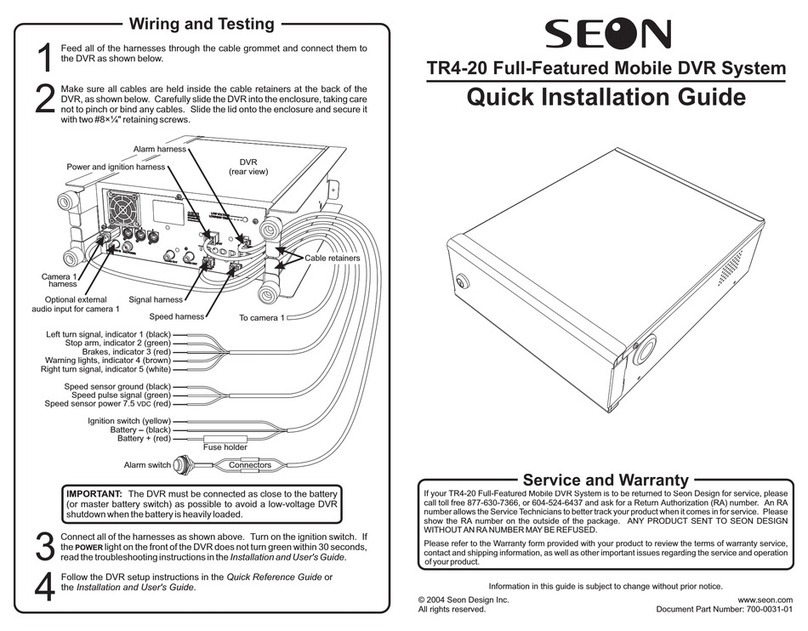
SEON Trooper TR9 User manual

Trooper® TR9 Mobile DVR System
Installation and User’s Guide
*700-0034*
Document part number 700-0034 R002

Seon Design® Inc.
Seon Design Inc. is a specialist in the design and manufacture of video
surveillance systems for mobile applications. Seon has been the preferred
solutions provider for the pupil transportation industry since 1999. Today,
we are proud that our success in this area has made us the leading
manufacturer of mobile video surveillance systems in North America.
Contact Information
Seon Design Inc.
Unit 111, 3B Burbidge Street
Coquitlam, BC
Canada V3K 7B2
Telephone 604.941.0880
Toll Free Telephone 1.877.630.7366
Fax 604.941.0870
Toll Free Fax 1.866.664.3677
Web site www.seon.com
Seon Design Inc. Trademarks
Seon Design Inc. holds the following trademarks:
Trooper® is a registered trademark of Seon Design Inc.
“Seon Design” is a registered trademark of Seon Design Inc.
The Seon logo ( ) is a registered trademark of Seon Design Inc.
In this User Manual there are references to trademarks, registered
trademarks, and product names not owned by Seon Design Inc. that are the
property of their respective owners. They are used in this User Manual for
identification purposes only.
User Manual Revision
This is the March 2008 revision for this User Manual and is copyright,
March 2008 of Seon Design Inc. All rights reserved.
2

Exclusion of Liability
SEON DESIGN INC.:
(a) MAKES NO REPRESENTATION,WARRANTY,GUARANTEE OR COVENANT,
EXPRESS OR IMPLIED,AS TO THE ACCURACY,SUFFICIENCY OR SUITABILITY
OF ANY TECHNICAL OR OTHER INFORMATION PROVIDED IN THIS USER
MANUAL OR ANY OTHER USER OR OTHER MANUAL OR OTHER
DOCUMENTATION PROVIDED BY SEON DESIGN INC.WITH RESPECT TO THE
PRODUCT(S)DESCRIBED HEREIN,INCLUDING WITHOUT LIMITATION ANY
DESCRIPTION OF GOODS OR SERVICES,SPECIFICATIONS,MODELS,DRAWINGS,
OR DIAGRAMS.
(b) DOES NOT ASSUME AND SHALL NOT BE SUBJECT TO AND DISCLAIMS ANY
AND ALL RESPONSIBILITY AND/OR LIABILITY FOR LOSSES,DAMAGES,COSTS
OR EXPENSES ARISING OUT OF BREACH OF CONTRACT OR OF WARRANTY,
TORT (INCLUDING NEGLIGENCE AND STRICT LIABILITY)OR OTHERWISE,
WHETHER SPECIAL,DIRECT,INDIRECT,CONSEQUENTIAL,INCIDENTAL,
SPECIAL OR CONTINGENT,WHICH MIGHT ARISE OUT OF THE USE OF SUCH
INFORMATION.THE USE OF ANY SUCH INFORMATION WILL BE ENTIRELY AT
THE USER’S RISK;AND
(c) EXPRESSLY DISCLOSES THAT IF THIS MANUAL IS WRITTEN IN ANY
LANGUAGE OTHER THAN ENGLISH,THAT ALTHOUGH SEON DESIGN INC.HAS
USED REASONABLE CARE TO MAINTAIN THE ACCURACY OF THE
TRANSLATION FROM THE ENGLISH LANGUAGE,THE ACCURACY OF SUCH
TRANSLATION IS NOT GUARANTEED OR WARRANTED BY SEON DESIGN INC.
PLEASE REFER TO THE ENGLISH LANGUAGE VERSION OF THIS USER MANUAL
FOR APPROVED SEON CONTENT.THE ENGLISH LANGUAGE VERSION IS
AVAILABLE UPON REQUEST FROM THE SEON CUSTOMER SERVICE
DEPARTMENT.
PLEASE REFER TO THE SEON DESIGN INC.PRODUCT WARRANTY APPLICABLE
TO THE PRODUCT(S)DESCRIBED IN THIS USER MANUAL WHICH EXCLUSIVELY
SETS FORTH SEON DESIGN INC.’S ENTIRE LIABILITY ARISING FROM OR IN
CONNECTION WITH SUCH PRODUCT(S)AND THEIR USE AND THE EXCLUSIVE
REMEDIES AVAILABLE FOR PURCHASERS AND USERS THEREOF.
Document Part Number
This User Manual is valid for Seon Design Inc. Document Part Number
700-0034.
PRINTED IN CANADA
3

Table of Contents
Features......................................................................................................5
Unpacking Your TR9 DVR ..........................................................................6
Docking Tray Installation.............................................................................7
Wiring the DVR ...........................................................................................8
Power and Ignition Harness ...................................................................9
Camera Harness ....................................................................................9
Alarm Harness .....................................................................................10
Vehicle Signal Harness ........................................................................10
CAN (SAE-J1939) Signal Harness .......................................................10
Speed Harness ....................................................................................11
GPS Sensor and Harness ....................................................................11
Operating the DVR....................................................................................12
Front Panel Controls ............................................................................12
Detachable Keypad (ordered separately) .............................................14
........................................................................................16Video Search
...........................................................................................18Smart-Start
........................................................................18Advanced Smart-Temp
Configuring the DVR .................................................................................19
Password Entry ....................................................................................19
Main Menu ...........................................................................................20
Set Time and Date Menu......................................................................20
Timer Settings Menu ............................................................................21
Camera Titles Menu .............................................................................22
Motion Recording Menu .......................................................................22
Record Menu........................................................................................24
Signal/Speed/GPS Menu......................................................................25
Network Menu ......................................................................................26
Buzzer Menu ........................................................................................27
Hard Drive Menu ..................................................................................28
System Menu .......................................................................................29
Troubleshooting ........................................................................................30
Power Problems...................................................................................30
Video Problems....................................................................................31
Audio Problems....................................................................................31
.............................................................................................32Maintenance
...........................................................................32Cleaning the Camera
....................................................32Cleaning the DVR and Docking Tray
Changing the DVR Ventilation Filter .....................................................32
Specifications............................................................................................33
Recording Time....................................................................................35
.......................................37SEON DESIGN® INC. PRODUCT WARRANTY

Features
The Trooper TR9 Mobile DVR System can record and play back audio, video, vehicle
data, and GPS information. The TR9 DVR provides the following features:
•Extremely rugged design, engineered specifically for mobile use
•Nine channels of high-quality video recording (720×484 resolution)
•Two channels of high-quality audio recording
•Five vehicle signal status inputs, one speed sensor input, one GPS data input
•CAN vehicle data interface (SAE-J1939 compliant)
•Configurable image quality and recording speed
•Alarm event or motion triggered fast recording speed
•Extended recording times using “hot-swappable” hard drives up to 320 Gigabytes
total capacity (two 160 GB hard drives)
•On-screen display of:
▪Time, date, vehicle identification, and camera name
▪GPS data, including location and vehicle speed
▪Five vehicle signal inputs and system voltage
•Repeat recording, user selectable on or off
•Variable delay-on and delay-off recording, user selectable from 0 to 60 minutes
•Thirteen daily/weekly timers to set DVR recording speed and start/stop times
Smart-Start™ power-up protection that prevents potential DVR damage from
voltage spikes and drops during vehicle start-up
•
Advanced Smart-Temp™ controls DVR heating and cooling functions to ensure
optimum performance at high and low operating temperatures
•
•Temporary power switch for setup and playback without turning on the vehicle
ignition
•Front panel audio and video output jacks for setup and playback
•Detachable keypad for operating and configuring the DVR
•Video playback search functions based on file segment, date/time, or alarm event
•Front panel CompactFlash® memory card slot for saving images and video
•Ethernet port for remote operation over a Local Area Network or the Internet
5

Unpacking Your TR9 DVR
Your TR9 DVR includes the following parts:
DVR with one or two (optional) removable disk drives and two disk
lock keys (cylindrical keys)
Docking tray with two door keys (flat keys), eight mounting screws,
one cable grommet, and one hole plug
Power and ignition harness with inline fuse holders and butt-splice
wire connectors
Alarm signal harness, customized to interface with existing silent
alarm switches
Vehicle signal harness (for brakes, turn signals, stop and warning
lights)
Camera harness or camera with harness (if purchased)
Speed signal harness (if purchased)
GPS receiver and harness (if purchased)
CAN (SAE-J1939 compliant) signal harness (if purchased)
Your TR9 DVR does not include the keypad which must be ordered separately.
Detachable keypad and cable
If any of the parts are missing or you would like to purchase, please contact your sales
representative at Seon Design.
6

Docking Tray Installation
The TR9 DVR can be mounted horizontally (on the floor or on a shelf) or vertically
upright (against a wall or bulkhead).
CAUTION! Do not mount the TR9 DVR in an inverted position.
The DVR could fall from the docking tray when the door is opened, injuring the
operator and damaging the DVR.
1 Use one of the flat keys to unlock the docking tray door. Slide the DVR out of the
docking tray.
2 Use a Phillips screwdriver to remove the five machine screws that fasten the
termination panel to the docking tray. Remove the termination panel from the
docking tray.
Docking tray door lock
Machine screws (×5)
3 Install the cable grommet in the access hole where the wiring harnesses enter the
docking tray. Install the hole-plug in the unused access hole.
4 Use the four enclosed #10×¾” metal screws or #10×1” self drilling screws to fasten
the docking tray to a sturdy horizontal or vertical surface. Make sure the mounting
location allows access to the four machine screws that secure the termination panel
to the docking tray.
5 Install the wiring harnesses as described in the Wiring instructions starting on page
8of this manual.
6 Fasten the termination panel to the docking tray using the five machine screws that
were removed in step 2.
7 Slide the DVR into the docking tray. Close and lock the docking tray door.
Termination panel
Docking tray
DVR Cable grommet
Docking tray
mounting holes (×4)
7

Wiring the DVR
All TR9 wiring harnesses plug into connectors on the termination panel of the docking
tray. The termination panel must be removed from the docking tray to connect the
wiring harnesses. Follow the instructions on page 7of this manual to remove the
termination panel and to install the cable grommet and hole plug in the docking tray
access holes.
NOTE: Audio input jacks 1 and 2 are connected in parallel with the audio inputs of
cameras 1 and 2, respectively. If you connect remote microphones to the audio input
jacks, the audio signals from the camera harness must be disconnected inside the
camera. See the Camera Harness section of this manual on page 9for details.
The wiring harnesses enter the docking tray through one of the cable access holes.
Leave enough slack in the cables to allow the termination panel to be removed with the
harnesses attached.
The wiring harnesses can be surface mounted or concealed. If a harness is surface
mounted, ensure that it is secured at frequent points and protected from sharp corners.
If a harness is concealed, pull it from the un-terminated end to minimize the size
requirements of conduits and access holes.
The standard wiring harness length is 20 feet (6m) long. Please contact Seon Design if
you need a longer harness.
8

Power and Ignition Harness
1A inline fuse to ignition switch
Butt-splice wire connectors
Red: Battery + (thru 10A inline fuse)
Black: Battery –
Yellow: Ignition Switch (thru 1A inline fuse)
NOTE: The power harness must be connected as close to the battery (or the
master battery switch) as possible to filter power surges and to avoid a low-voltage
DVR shutdown when the battery is heavily loaded.
Camera Harness
Blue: Video –
Yellow: Video +
NOTE: Audio input jacks 1 and 2 on the termination panel are connected in parallel
with the audio inputs of cameras 1 and 2, respectively. If you connect remote
microphones to the audio input jacks, the audio signals from the camera harness
must be disconnected inside the camera.
White: Audio –
Green: Audio +
Black: Power –
Red: Power +
Circuit board inside camera
9

Alarm Harness
Black: Alarm switch –
The alarm harness is used to trigger the recording of an alarm event and to increase the
recording quality and speed for a configurable time period after the alarm. The
recorded alarm event can be used during video playback to quickly search for important
incidents.
Connect the red wire to the black wire (or to ground) through a normally open alarm
switch. Use the vehicle’s silent alarm switch if possible.
See the Record Menu on page 24 of this manual for configuration details and Video
Search on page 16 for alarm search details.
Vehicle Signal Harness
NOTE: Always connect the vehicle signal inputs to a fuse-protected circuit.
Each input can be configured to display the status text when the signal is 12 VDC
(active high – default setting) or grounded (active low). The default text shown above
for each input can be changed. See the Signal/Speed/GPS Menu on page 25 of this
manual for configuring details.
CAN (SAE-J1939) Signal Harness
The CAN vehicle data interface (SAE-J1939 compliant) provides a connection to the
vehicle’s internal CAN data bus. Please contact Seon Design about a custom interface
cable for your vehicle.
Red: Alarm switch +
Black: Ch.1 - LT (Left Turn Signal)
Green: Ch.2 - STP (Stop Arm)
Red: Ch.3 - BRK (Brakes)
White: Ch.5 - RT (Right Turn Signal)
Brown: Ch.4 - WRN (Warning Lights)
10

Speed Harness
All speed signal inputs are protected against short circuits and transients. The speed
pulse input is designed to interface to speed sensors that output a pulse signal of up to
20 VDC, 20 VAC peak-to-peak, or to speed sensors that use ‘open-collector’ style
outputs. See the Signal/Speed/GPS Menu on page 25 of this manual for speed
calibration information.
Contact Seon Design for recommended speed sensors to use with the TR9 DVR
System. Refer to the documentation that comes with the speed sensor for further
information on connecting to an external speed sensor.
The TR9 DVR System can also interface directly to some types of transmission control
modules (TCM) in vehicles. Please contact Seon Design for details about interfacing to
different TCMs.
GPS Sensor and Harness
The GPS receiver must be mounted horizontally (parallel to the ground), on the top of
the vehicle to obtain a clear ‘line-of-sight’ view of the GPS satellites overhead. The
GPS receiver has a built-in magnetic base that holds securely to steel panels. For non-
steel or composite panels, use an outdoor weatherproof silicone to secure the receiver
to the top of the vehicle.
NOTE: Use an outdoor weatherproof silicone to seal the hole where the GPS cable
goes through an exterior panel.
Black: Signal Ground (0 VDC)
Green: Speed Pulse Signal
Red: Speed Sensor Power (7.5 VDC)
Black
White
Green
Red
11

Operating the DVR
To view live or recorded video on the TR9 DVR:
1 Connect a video monitor to the audio and video output jacks on the front panel of
the DVR.
2 Plug the detachable keypad cable into the socket on the front panel of the DVR.
3 Use the front panel controls and the detachable keypad to operate the DVR, as
described below.
Front Panel Controls
CAUTION! The CompactFlash (CF) memory card can only be inserted with the
card label facing up. Forcing the CF card into the slot could damage the
internal connector. Slowly insert the card until the connector engages — the
card should feel snug in the slot.
CAUTION! Unlocking and removing a disk drive while it is recording will
delete the current video segment. Pressing the STOP button on the keypad or
turning the vehicle ignition OFF is the only safe way of correctly creating the
video segment.
12

AUDIO OUT and Connect a video monitor to these jacks to view live or recorded
VIDEO OUT jacks video, or to configure the DVR.T
COMPACT FLASH (CF)
card slot
The DVR can save audio and video information to a removable
Compact Flash (CF) memory card. The DVR system software
can also be updated from a CF card.
Disk drive access light This red light is on when the DVR is reading or writing data on
the disk drive. Do not unlock the disk drive while this light is on.
Disk drive lock Use a key to unlock the disk drive before attempting to pull the
disk drive out of the DVR. Do not unlock the disk drive while the
disk drive access light is on.
Disk drive power light This green light is on when a disk drive is properly installed and
locked. The DVR can only access the disk drive while this light is
on.
cable socket Plug the keypad cable into this socket to operate or configure the
DVR from the keypad.
KEYPAD
LOW VOLTAGE light This red light turns on steady when the DVR input voltage drops
below 10.5 VDC. The DVR will stop recording while this light is
on. The light will turn off and recording will resume when the
DVR input voltage rises above 10.9 VDC.
LOW/HIGH TEMP light This red light will flash if the DVR temperature drops below 5°F
(-15°C) or rises above 140°F (60°C). The DVR will stop
recording while this light is flashing. Recording will resume when
the internal heater and fan bring the DVR temperature within the
operating temperature range.
TEMP POWER button Press this button for 5 seconds to turn DVR power on or off while
the ignition switch is off. Power will automatically turn off if the
ignition switch is off and no keypad buttons are pressed for 5
minutes. Press this button for 5 seconds to turn DVR power on
and start recording during the delay-on period. Press this button
for 5 seconds to turn DVR power off during the delay-off period.
13

Detachable Keypad (Ordered separately)
The TR9 DVR can be controlled and configured from the detachable keypad shown
below.
CHANNEL (1-9) While the DVR is in multi-channel display mode, press a CHANNEL
buttons button to display a single, full-screen image. While in picture-in-picture
(PIP) display mode, press a button to select a full-screenCHANNEL
image, and then press a second button to select a PIP image.CHANNEL
button Press this button to transfer audio and video information to a Compact
Flash (CF) memory card. Read the
COPY
TR-CFR Installation and User’s
Guide (document part number 700-0021) for detailed instructions.
DISPLAY button Press this button to toggle the text overlay information on and off. The
text information includes date and time, vehicle and camera titles, signal
status, vehicle speed, playback or recording speed, and disk usage.
button While entering a password, configuring the DVR, or searching for video,
press this button to accept a menu or search selection.
ENTER
wheel While the DVR is paused, turn the wheel clockwise to advance one videoJOG JOG
frame or counter-clockwise to go back one frame. During DVR configuration,
use the wheel to quickly change menu values or title characters.JOG
MENU button While the DVR is stopped, press this button to start configuring the
DVR. During configuration, press this button to go back to a previous
menu. From the Main Menu press this button to stop configuring and
resume normal DVR operation.
MODE button While the DVR is recording, playing or paused, press this button to
switch between several multi-channel video display layouts.
PAUSE button Press this button to pause video playback and display a still frame. Use
the wheel to display the next or previous still frames.JOG
PLAY button While the DVR is not recording, press this button to playback recorded audio
and video. Use the SHUTTLE wheel to control playback speed and direction.
POWER light This green light is on when the keypad is plugged into the DVR and DVR
power is on. The light flashes off momentarily when a button is pressed.
button While the DVR is stopped, press this button to start recording audio andREC
video information.
14

button While the DVR is stopped, press this button to display a search menu.
You can search the recorded audio and video for a particular video
segment, alarm event, or date and time. Use the
SEARCH
JOG wheel to select a
segment or alarm event, then press the ENTER button to play the
selected video.
button Press this button to change the video channel selections in a multi-SELECT
channel video display layout. Press one of the buttons to assignCHANNEL
that channel to the currently selected display panel. Press the ENTER
button to advance to the next panel without changing the channel.
wheel While the DVR is playing, turn theSHUTTLE SHUTTLE wheel clockwise or counter-
clockwise to increase the forward or reverse playback speed from 2 to
600 times normal speed. The further you turn the SHUTTLE wheel, the
faster the playback speed. When you release the SHUTTLE wheel,
playback returns to normal speed.
STOP button While the DVR is recording, playing or paused, press this button to stop
the DVR. If no other buttons are pressed within 10 seconds, the DVR
will automatically start recording, if scheduled to do so. During the 10
seconds, press the MENU, SEARCH, PLAY, or buttons toCOPY RECORD
start an operation.
button While the DVR is recording, playing or paused in full-screen display
mode, press this button to display the image at 200% magnification.
Use the
ZOOM
wheel to pan left and right, or up and down. Press theJOG
button to toggle the pan direction between left/right and up/down.ENTER
15

Video Search
The TR9 DVR provides a versatile video search function that quickly locates video
clips from a list of video segments, from a list of alarm events, or by date and time.
To search for a video clip:
1 Press the STOP button to stop recording or playback.
2 Press the button to display the Search Menu.SEARCH
To search for a video segment:
1 Turn the wheel to select By Segment List from the main Search Menu.JOG
2 Press the button to display the Segment Search list.ENTER
16

3 Turn the wheel to select a video segment.JOG
4 Press the button to play the video segment.ENTER
To search for an alarm:
1 Turn the wheel to select By Alarm List from the main Search Menu.JOG
2 Press the button to display the Alarm Search list.ENTER
ALARM SEARCH
0001 PL 2005/09/09 07:35:26 HDD-1
0002 PL 2005/09/09 03:05:12 HDD-1
0003 A1 2005/09/12 07:31:45 HDD-1
0004 V1 2005/09/12 03:02:41 HDD-1
0005 PL 2005/09/13 07:36:19 HDD-1
0006 A1 2005/09/13 03:06:08 HDD-1
0007 PL 2005/09/14 07:38:21 HDD-1
0008 A1 2005/09/14 03:03:02 HDD-1
0009 V9 2005/09/15 07:32:35 HDD-1
0010 PL 2005/09/15 03:05:15 HDD-1
3 Turn the JOG wheel to select an alarm. The alarm codes are:
A1 Indicates an external alarm signal
PL Indicates a power loss
V1 Indicates the loss of one video signal (V1 to V9 for channels 1 to 9)
VA Indicates the loss of all video signals
4 Press the button to play the selected alarm.ENTER
To search by date and time:
1 Turn the wheel to select By Date Time from the main Search Menu.JOG
2 Press the button to display the Date Time Search menu.ENTER
17

3 Turn the JOG wheel to change the value of each entry in the date and time. Press
the button to advance to the next entry.ENTER
4 When the date and time have been entered, press the SEARCH button to play the
video starting at the selected date and time, or press the MENU button to return to the
main Search Menu.
Smart-Start
The TR9 DVR displays and records the input voltage. This can be a very helpful
diagnostic tool if you encounter low voltage problems with vehicle power supplies.
If the voltage to the DVR is too low, the quality of the video signal from the camera
will be very poor, resulting in a poor recording. In addition to the on-screen voltage
display, the TR9 DVR incorporates a low voltage indicator on the front panel of the
DVR.
If the voltage to the DVR drops below 10.5 VDC for more than 30 seconds, a Power
Loss (PL) alarm will be recorded, the red low voltage light will turn on and the DVR
will stop recording. When the voltage rises above 10.9 VDC, the red low voltage light
will turn off and the DVR will resume normal operation.
Advanced Smart-Temp
The TR9 DVR incorporates several advanced features not found in any other system on
the market. The Advanced Smart-Temp feature is a key example of how Seon Design
is leading the way in developing solutions that benefit the customer directly.
Most computer disk drives are designed to operate between 40°F and 120°F. In many
geographical areas, the temperature drops well below 40°F, and quite often below
32°F. Advanced Smart-Temp controls the DVR heater and fan to maintain a safe
operating temperature. If the temperature inside the DVR drops below 40°F (5°C) or
rises above 113°F (45°C), Advanced Smart-Temp flashes the red low/high temp light
on the front panel of the DVR.
If the temperature inside the DVR rises above 140°F (60°C), Advanced Smart-Temp
records a Power Loss (PL) alarm, turns off the disk drives, and flashes the red low/high
temp light on the front panel of the DVR. The DVR fan continues operating to bring
the DVR back to a safe operating temperature below 113°F (45°C).
18

Configuring the DVR
To configure the TR9 DVR:
1 Connect a video monitor to the audio and video output jacks on the front panel of
the DVR.
2 Connect the detachable keypad cable to the socket on the front panel of the DVR.
3 Use the detachable keypad to configure the DVR, as described below.
CHANNEL (1-9) While configuring the motion menu, press one of these buttons to
buttons display the motion detection grid for a channel.
button Press theENTER ENTER button to view a selected menu item or to accept the
currently selected value and advance to the next value on a screen.
wheel Turn the wheel forward or backward to select a menu item or toJOG JOG
change a selected value.
MENU button While the DVR is stopped, press the MENU button to start configuring
the DVR. During configuration, press this button to go back to a
previous menu. From the Main Menu, press this button to stop
configuring and resume normal DVR operation.
POWER light This green light is on when the keypad is plugged into the DVR and
DVR power is on. The light flashes off momentarily when a button is
pressed.
STOP button While the DVR is recording, playing or paused, press this button to stop
the DVR. If no other buttons are pressed within 10 seconds, the DVR
will automatically start recording, if scheduled to do so. During the 10
seconds, press the MENU button to display the Main Menu.
Password Entry
If passwords are enabled on the System Menu (page 28), you must enter a valid Level 3
password to view the Main Menu and configure the DVR. Turn the JOG wheel to
change each character of the password. Press the ENTER button to advance to the next
character or to submit the password when all six characters have been entered.
19

Main Menu
Press the STOP button and then press the MENU button to view the Main Menu. Use the
wheel to select a menu item. Press the button to view the selected menu item.JOG ENTER
Set Time and Date Menu
Day of the week is set automatically after day, month and year are set.DATE
Select YES to automatically adjust the DVR clock for Daylight Saving
Time. As of 2007, on the second Sunday in March, the time changes from
02:00 am to 03:00 am Daylight Saving Time. On the first Sunday in
November, the time changes from 02:00 am to 01:00 am Standard Time.
AUTO DAYLIGHT
SAVING TIME
20
Table of contents
Other SEON DVR manuals
SEON
SEON HX16 Instructions for use
SEON
SEON Explorer Assembly instructions
SEON
SEON TR4-10 User manual
SEON
SEON TL-HD User manual
SEON
SEON DX12 Installation and operation manual
SEON
SEON Explorer DX12 Plus User manual
SEON
SEON Trooper TL4 User manual
SEON
SEON Explorer TX8 User manual
SEON
SEON Trooper Basic TR1-10 User manual

SEON
SEON Explorer TX8 Operator's manual

SEON
SEON Explorer Operation manual

SEON
SEON Explorer TX8 User manual
SEON
SEON Trooper TR4 User manual
SEON
SEON Trooper TL2 User manual
SEON
SEON Explorer EX8Plus Mobile User manual
SEON
SEON Trooper TL Quick guide
SEON
SEON Trooper TL-HD User manual

SEON
SEON TL-HD Operating instructions
SEON
SEON TH8 Operator's manual

SEON
SEON Trooper TL4 User manual
