sewerin SeCorr 08 User manual

Operating
Instructions
SeCorr® 08

Measurable success by Sewerin equipment
Congratulations.
You have chosen a quality instrument manufactured by Hermann
Sewerin GmbH.
Our equipment will provide you with the highest standards of perfor-
mance, safety and efciency. They correspond with the national and
international guide-lines.
Please read and understand the following operating instructions before
using the equipment; they will help you to use the instrument quickly and
competently. If you have any queries we are available to offer advice
and assistance at any time.
Yours
Hermann Sewerin GmbH
Robert-Bosch-Straße 3
33334 Gütersloh, Germany
Tel.: +49 5241 934-0
Fax: +49 5241 934-444
www.sewerin.com
info@sewerin.com
Sewerin USA LLC
2835 Haddoneld Road
Pennsauken, NJ 08110-1108
Phone: +1 215-852-8355
Fax: +1 856-662-7070
www.sewerin.net
sewerin-usa@sewerin.net
SEWERIN SARL
17, rue Ampère – BP 211
67727 Hoerdt Cedex, France
Tél. : +33 3 88 68 15 15
Fax : +33 3 88 68 11 77
www.sewerin.fr
sewerin@sewerin.fr
Sewerin Ltd
Hertfordshire
UK
Phone: +44 1462-634363
www.sewerin.co.uk
info@sewerin.co.uk
SEWERIN IBERIA S.L.
Centro de Negocios Eisenhower
Avenida Sur del Aeropuerto
de Barajas 24, Ed. 5 Of. 2C
28042 Madrid, España
Tel.: +34 91 74807-57
Fax: +34 91 74807-58
www.sewerin.es
info@sewerin.es
Sewerin Sp.z o.o.
ul. Annopol 3
03-236 Warszawa, Polska
Tel.: +48 22 519 01 50
Fax: +48 22 519 01 51
Tel. kom.+48 501 879 444
+48 608 01 37 39
www.sewerin.com

Illustration SeCorr 08
Rotary regulator
Menu key
ON/OFF key
Light key
Central screen
Enter key
Arrow keys

RT 06
A
Hz
A
Hz
Filter key (4)
LED (5), plastic,
low pass
LED (6), metal,
Wideband
Status-LED (1)
Power supply (3) Microphone connection (2)
Illustration RT 06

Operating Instructions
26.04.2010 – V 4.X – 103923 – en
SeCorr® 08

Warranty & Used symbols
Used symbols:
CAUTION!
This symbol is used to indicate dangers which may
either result in hazards for the operators or in severe
damage – or even destruction – of the product.
Note:
This symbol is used to call attention to information
and tips which may be helpful and which are exceed-
ing the basic operating procedures.
The following instructions must be complied with in order for any warranty
to be applicable in respect of the functionality and safe operation of this
equipment.
Hermann Sewerin GmbH accepts no liability for any damages resulting
from failure to observe these instructions. The warranty and liability provi-
sions of the terms of sale and delivery of Hermann Sewerin GmbH are not
affected by the information given below.
The product must only be operated after the relevant operating instruc-z
tions have been read and understood.
The product must only be used for its intended purpose.z
The product is only suitable for use in industrial and commercial ap-z
plications.
Repairs must only be carried out by a specialist technician or by otherz
suitably trained personnel.
Changes or modications to this product must not be carried out with-z
out approval from Hermann Sewerin GmbH. The manufacturer cannot
be held responsible for damages if non-approved modications have
been made.
All repairs must be carried out using replacement parts that have been z
approved by Hermann Sewerin GmbH.
The manufacturer reserves the right to make technical modications in z
the course of further development.
Generally applicable safety and accident-prevention regulations must be
complied with, in addition to the information provided in this manual.

I
Contents Page
1 Function description...............................................................1
1.1 Usage........................................................................................1
2 Use............................................................................................2
2.1 First use ....................................................................................2
2.2 Switching ON/OFF ....................................................................2
2.3 Channel assignment .................................................................3
2.4 Radio transmitter RT 06 ............................................................5
3 Operating elements.................................................................6
3.1 ON/OFF key ..............................................................................6
3.2 Rotary regulator ........................................................................6
3.3 Enter key ...................................................................................7
3.4 Menu key...................................................................................7
3.5 Left/right arrow keys..................................................................7
3.6 Up/down arrow keys..................................................................7
3.7 Light key....................................................................................8
3.8 Adjusting the contrast................................................................8
4 Performing a correlation measurement ................................9
4.1 Entering pipe data .....................................................................9
4.2 Starting a measurement..........................................................10
4.3 Evaluating the result................................................................ 11
4.3.1 Filtering ................................................................................12
4.3.2 Cursor ..................................................................................12
4.3.3 Zoom ....................................................................................13
4.4 Continuing a measurement .....................................................14
5 Measuring the sound velocity..............................................15
5.1 General information.................................................................15
5.2 Performing a measurement.....................................................15
6 Charging equipment .............................................................17
6.1 Battery state ............................................................................18
6.2 Charging process/battery maintenance ..................................19

II
Contents Page
7 Menu.......................................................................................20
7.1 Menu structure ........................................................................20
7.2 Listen.......................................................................................21
7.2.1 AQUAPHON.........................................................................21
7.2.1.1 Display ..............................................................................22
7.2.1.2 Assignment of keys...........................................................23
7.2.1.3 Sensitivity..........................................................................23
7.3 File ..........................................................................................23
7.3.1 Store.....................................................................................23
7.3.2 Open ....................................................................................24
7.3.3 Delete...................................................................................25
7.4 Filtering ...................................................................................25
7.4.1 Automatic ltering.................................................................25
7.4.2 Manual ltering.....................................................................25
7.4.3 Setup....................................................................................28
7.4.3.1 Filter limits.........................................................................28
7.4.3.2 Filter basis.........................................................................28
7.4.3.3 Filtering method ................................................................29
7.5 Measurement method .............................................................29
7.6 Parameter ...............................................................................29
7.6.1 Noise suppression................................................................29
7.6.2 Measuring time.....................................................................31
7.6.3 Summation/average .............................................................31
7.6.4 Mode of curve ......................................................................31
7.6.5 Correlation............................................................................31
7.6.6 Sampling frequency .............................................................32
7.6.7 Table.....................................................................................32
7.6.8 Standard values ...................................................................32
7.7 Components............................................................................33
7.8 Setup.......................................................................................34
7.8.1 Date, time.............................................................................34
7.8.2 Language .............................................................................34
7.8.3 Radio/cable ..........................................................................34
7.8.4 System .................................................................................34
7.8.5 Name....................................................................................35
7.8.6 Service .................................................................................35
8 Methods of optimising measuring results..........................36
8.1 Changing the number of averaging processes .......................36
8.2 Using lters .............................................................................36

III
Contents Page
8.3 Automatic ltering....................................................................37
8.4 Checking the microphone connections ...................................37
8.5 Using accessories ...................................................................37
8.6 Changing the location .............................................................37
8.7 Saving time .............................................................................37
9 Communication with PC.......................................................38
9.1 Requirements..........................................................................38
9.2 Software installation ................................................................38
10 Technical data........................................................................40
11 Accessories ...........................................................................41
12 Error messages .....................................................................42
13 Annexe ...................................................................................44
13.1 EC Declarations of Conformity................................................44
13.2 Advice on disposal ..................................................................44
13.3 History of changes ..................................................................45
14 Index.......................................................................................46

1
1 Function description
1 Function description
1.1 Usage
The correlator SeCorr 08 permits to detect leakage points an
directly buried pressure line systems according to the correla-
tion principle. Sensitive microphones are used to record leakage
noise on accessible installations and ttings. These recordings
are wireless transmitted to the correlator.
SeCorr 08 calculates then the exact leakage position using the
Fast Fourier Transformation (FFT = mathematic algorithm).
Supplementary functions are available to improve e.g., the indi-
cation of leaks, to enter several pipe sections or to measure the
sound velocity.
The RT 06 radio transmitter can be used to measure fully auto-
matically the input level of the microphone and to set the level
control of the amplier to the optimum value. Characteristics and
parameters – such as the used microphone type, the charge state
of batteries and the amplier setting – are wireless transmitted to
the correlator for further evaluation.
Note:
These operating instructions are based on soft-
ware release 4.X, with „X“ standing for any number.
The currently installed software version of your
SeCorr 08 is displayed after switching on the device.
Future releases are subject to change!

2
2 Use
2 Use
2.1 First use
CAUTION!
Before placing SeCorr 08 and RT 06 for the rst
time into service, make sure that all used batteries
are completely charged. If the batteries are only
partially charged, the capacity of the batteries may
be reduced thus leading to shorter operation.
2.2 Switching ON/OFF
Position both piezo micro-z
phones at accessible fitting
parts. If the circular magnet
is screwed on the piezo mi-
crophone, it may be required
to remove the circular, rmly
adhering protective disk from
the magnet.
Plug both microphone con-z
nectors into the sockets of the
radio transmitter RT 06. If you
want to use only one RT 06, it
is required to connect a micro-
phone directly to input 2 of the
SeCorr 08.
On the RT 06, LED 1 must
be lit.
Connect the headphones toz
socket 3 of the SeCorr 08.
Switch on the SeCorr 08 by z
pressing the ON/OFF key for
a couple of seconds.
2
1

3
2 Use
The initial screen is briefly
displayed, containing informa-
tion on the release number of
the software and the battery
capacity.
Then the central screen ap-
pears (see back of cover
page). From this screen, you
can access the individual
menus (menu key) or start the
desired functions.
Keep thezON/OFF key pressed
until the device switches off.
2.3 Channel assignment
Channel 1 Channel 2
Is indicated together
with message
„battery empty“
RT 06-1 RT 06-2
Indication Left Right
Type with one signal
channel
Director connection
of microphone to
SeCorr 08
Radio transmitter 2
(orange)
Type with two sig-
nal channels
Radio transmitter
1 (blue)
Radio transmitter
2 (orange)
Only one radio
transmitter is used
(e. g. in case of a
defect):
Variant 1z
(blue radio trans-
mitter in use)
Radio transmitter 1
(blue)
Direct connection
of microphone to
SeCorr 08
Variant 2z
(orange radio
transmitter in use)
Direct connection
of microphone to
SeCorr 08
Radio transmitter 2
(orange)
3

4
2 Use
During correlation measure-z
ments the noise intensity of
both microphone channels is
indicated to the left- and right-
hand side of the correlation
function.
Note:
The SeCorr 08 version with two transmitters permits
to connect a microphone directly two the SeCorr 08,
e.g., if a radio transmitter is defective (see also sec-
tion 7.8.3).
started
5
2 Use
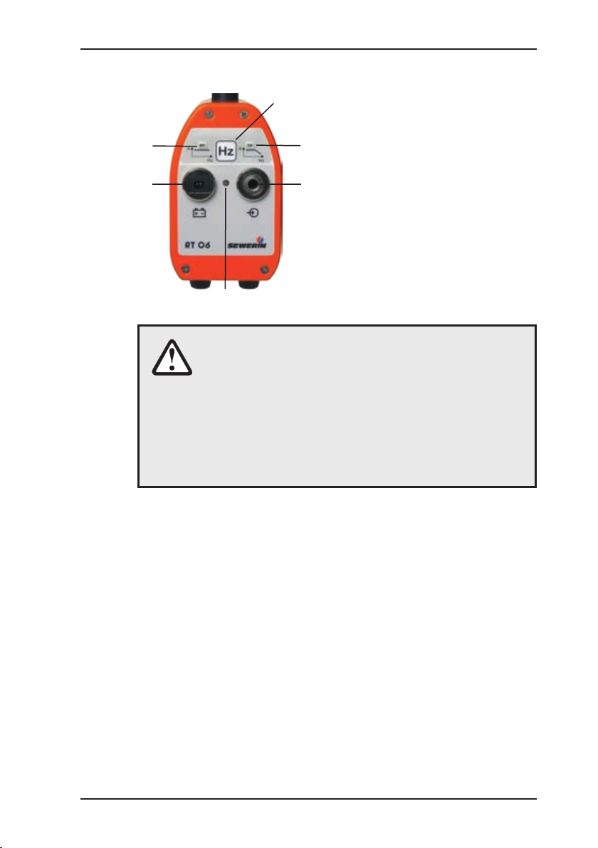
2.4 Radio transmitter RT 06
The radio transmitter RT 06
can be operated with different
sensors, EM30 microphones
and the HA hydrophone.
It is recommended to use the
active lter ZF01, if interfering
noise is to ltered out or if only
a specic acoustic frequency
range is to be transmitted to
the correlator SeCorr 08.
1
2
3
65
4
CAUTION!
Connect always rst the sensor to the measurement
location (by coupling the microphone to the slide
valve, hydrant, etc.). Then, switch on the RT 06 by
plugging the sensor into socket 2.
This sequence of steps ensures that the automatic
amplication in the RT 06 is quickly and properly
set.
The RT 06 is enabled when the sensor is plugged into socket 2.
Press the lter key 4 generally if plastic pipes are used. The right
LED 5 is lit to indicate the changeover. If this setting is selected,
only the low-pass frequencies are transmitted to the correlator.
This may help to increase the quality of the correlation mea-
surement. If the RT 06 is switched on, all frequencies are always
transmitted; the left LED 6 is lit.
The transport handle on top of the antenna can be used for car-
rying the device.
LED 1 shows the state of the RT 06:
Operation: green
Undervoltage: ashed red
Charging: 1 x ashing green
Buffering: 2 x ashing green
No charging: red (because temperature below 0 °C)

6
3 Operating elements
3 Operating elements
3.1 ON/OFF key
Press this key to switch the de-
vice on or off. Hold it pressed un-
til the SeCorr 08 is activated.
If the key is pressed only shortly,
the currently running function is
stopped (e.g., a correlation in
progress). If you have opened
the menu, you can use the ON/
OFF key to return to the next
higher menu level. Press the key
only shortly.
If a correlation is stopped, the
diagram (correlation function)
can be zoomed in. If any key is
pressed, the display returns to
normal representation.
3.2 Rotary regulator
Turn the Rotary regulator to
move the selection or the cursor
to the left/right or up/down.
You can use the Rotary regulator
to change values in numerical
entry elds (e.g., pipe length).
Press the Rotary regulator once
to change the direction of move-
ment from up/down to left/right or
vice versa.Pressing the Rotary
regulator has the same effect as
pressing the Enter key.

7
3 Operating elements
3.3 Enter key
Press this key to enable the cur-
rently selected function.If you
select „Cancel“ in the menu, the
display returns to the central
screen.
3.4 Menu key
Press this key to open the menu
(see section 7).
3.5 Left/right arrow keys
Press these keys to move to the
left or right within the selected
function. In some menus the
arrow keys can also be used for
selecting options.
You can access the next higher
menu level by pressing the left
arrow key. You can use this func-
tion only if the cursor is set to its
left or right end position.
3.6 Up/down arrow keys
Press these keys to move the
cursor up or down in a menu.
In some menus the Arrow keys
can also be used for selecting
options.

8
3 Operating elements
3.7 Light key
Use this key to switch the il-
lumination on or off. The illu-
mination automatically switch-
es off after a pre-set period
(see section 7.8.4).
3.8 Adjusting the contrast
The contrast of the display is au-
tomatically controlled in relation
to the temperature.
You can adjust the contrast
manually by holding the Light
key pressed while operating the
Up or Down Arrow key at the
same time.

9
4 Performing a correlation measurement
4 Performing a correlation measurement
4.1 Entering pipe data
Before starting a measurement, it is required to enter the pipe
data.
Select option pipe data usingz
the Arrow keys and conrm
your selection with the Enter
key.Then, enter the number of
pipe sections.
Depending on the type of ap-z
plication, select One, Two or
Three pipe sections with the
arrow keys. Conrm your se-
lection with the Enter key.
Enter the pipe length. Use z
the left or right arrow key to
change between the displayed
digits.
You can use the Up/Down z
arrow keys to increase or
reduce the displayed value in
increments.
Confirm the length with thez
Enter key.
In the list, select the materialz
of the pipe section using the
Arrow keys. You can also use
the direct option to enter the
sound velocity manually.
Pay attention to the following: z
The values in the list are ap-
proximate values and may be
subject to inaccuracies (see
section 5.)
In the displayed list, select thez
pipe diameter using Arrow keys.

10
4 Performing a correlation measurement
Note:
Apart from the default application, „Cross cor-
relation“, SeCorr 08 can also be used to perform
automatic correlations („Auto correlation“); refer to
chapter 7.6.5!
4.2 Starting a measurement
Select this function, if a measurement section is measured for
the rst time or if an error occurred during the rst measurement
(transmitter is not switched on, problems during connecting the
microphone, etc.).
Select start with the Arrow z
keys and conrm your selec-
tion with the Enter key.
Use the headphones to check
the measurement trend acous-
tically (safety instructions: see
section 7.2.1).
If necessary, repeat these en-z
tries for the second and third
pipe section.
pipe data
start
continue
A summary of the entered zpipe
data appears on the screen.
Select Start with the Arrow
keys. Press the Enter key.
The correlation measurement
starts.
Start
cancel
100.0 m
steel
125 mm
1280 m/s

11
4 Performing a correlation measurement
Press Cancel to return to thez
main menu.
Depending on the selected
settings (see section 7.6.2)
either 16, 32, 64 or 128 aver-
aging processes (i.e., meas-
urements) are performed.
The display shows the current-
ly performed measurement.
During the measurement, the
correlation function is continu-
ously updated.
The correlation measurement z
can be interrupted any time
by pressing the ON/OFF key
shortly.
An interrupted measurement
can always be resumed.
After the zmeasurement the re-
sult is displayed. The adjacent
illustration shows a correlation
example. The method of dis-
play depends on the setting
selected in the „Filter / Setup“
menu.
4.3 Evaluating the result
The correlation function uses
peaks to indicate where a leak
may be located. The time-delay
difference is displayed on the x
axis in ms (i.e., milliseconds).
The highest peak is automati-
cally highlighted.
pipe data
start
continue
pipe data
start
continue
Table of contents
Other sewerin Measuring Instrument manuals

sewerin
sewerin UT 9000 User manual

sewerin
sewerin EX-TEC PM 4 User manual

sewerin
sewerin EX-TEC Combi User manual

sewerin
sewerin COMBIPHON User manual

sewerin
sewerin EX-Tec HS 680 User manual

sewerin
sewerin Multitec 545 User manual

sewerin
sewerin Stethophon 04 User manual

sewerin
sewerin VARIOTEC 480 EX User manual

sewerin
sewerin SPE 2 User manual

sewerin
sewerin VARIOTEC 460 Tracergas User manual


