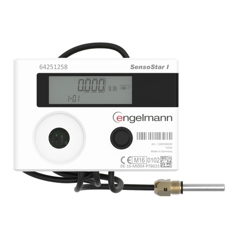
sewerin miniLec 4 User manual

Operating
Instructions

Measurable success by Sewerin equipment
Congratulations. You have chosen a quality instrument manufactured
by Hermann Sewerin GmbH.
Our equipment will provide you with the highest standards of perform-
ance, safety and efciency. They correspond with the national and in-
ternational guide-lines.
Please read and understand the following operating instructions before
using the equipment; they will help you to use the instrument quickly and
competently. If you have any queries we are available to offer advice
and assistance at any time.
Yours
Hermann Sewerin GmbH
Robert-Bosch-Straße 3
33334 Gütersloh, Germany
Tel.: +49 5241 934-0
Fax: +49 5241 934-444
www.sewerin.com
info@sewerin.com
SEWERIN SARL
17, rue Ampère – BP 211
67727 HOERDT CEDEX, France
Tél. : +33 3 88 68 15 15
Fax : +33 3 88 68 11 77
www.sewerin.fr
sewerin@sewerin.fr
Sewerin Ltd
Hertfordshire
UK
Phone: +44 1462-634363
www.sewerin.co.uk
info@sewerin.co.uk
SEWERIN IBERIA S.L.
Centro de Negocios “Eisenhower”
Avenida Sur del Aeropuerto
de Barajas 28, Of. 2.1 y 2.2
28042 Madrid, España
Tel.: +34 91 74807-57
Fax: +34 91 74807-58
www.sewerin.es
info@sewerin.es
Sewerin Sp.z o.o.
ul. Twórcza 79L/1
03-289 Warszawa, Polska
Tel.: +48 22 675 09 69
Tel. kom. +48 501 879 444
www.sewerin.pl
info@sewerin.pl

Illustration MiniLec 4 with full equipment (version HP)
Inlet for prelimi-
nary test
Inlet for
Main test,
Test of working
order and
Regulator
inspections
Buzzer
Keyboard
Outlet for Test of
working order
Suspension
Signal light/
infrared interface
LCD
Charging contacts

Overview
Operating keys
Switching the instrument on/off
(keep pressed for approx. 3 seconds)
Entries/conrming a selection (short pressing)
Changing between the operating menus
Selection of menu items
LCD
Test mode Type of gas
Battery state Flow rate
Unit
Pressure Unit

Operating Instructions
26.10.2016 – V3.XXX – 103999 – en
MiniLec® 4

Symbols used
CAUTION!
This symbol refers to important safety instructions.
Adhere strictly to these instructions to avoid material
damages!
Note:
This symbol refers to information and useful tips
which are exceeding the basic operating proce-
dures.
CAUTION! Danger of injuries!
This symbol refers to important safety instructions.
Adhere strictly to these instructions to avoid
injuries!

I
Contents Page
1 General information ................................................................1
1.1 Warranty....................................................................................1
1.2 Application purpose...................................................................2
1.3 Intended usage .........................................................................2
1.4 General safety instructions........................................................3
2 Equipment................................................................................4
2.1 Connections ..............................................................................4
2.2 Visual and audible signals.........................................................5
2.3 Infrared interface .......................................................................6
3 Operation .................................................................................7
3.1 Measuring mode .......................................................................7
3.1.1 General information regarding the measuring mode..............7
3.1.1.1 Switching on the device ......................................................7
3.1.1.2 User menu.........................................................................10
3.1.2 Setting the zero point ........................................................... 11
3.1.3 Test of working order............................................................12
3.1.3.1 Preparations......................................................................12
3.1.3.2 Execution ..........................................................................13
3.1.3.3 Analysis of working order..................................................14
3.1.4 Main test...............................................................................15
3.1.4.1 Preparations......................................................................15
3.1.4.2 Execution ..........................................................................16
3.1.5 Preliminary test ....................................................................17
3.1.5.1 Preparations:.....................................................................18
3.1.5.2 Execution ..........................................................................18
3.1.6 Regulator inspection ............................................................20
3.1.6.1 Preparations......................................................................20
3.1.6.2 Execution ..........................................................................20
3.1.6.3 Dynamic pressure .............................................................22
3.1.6.4 Static pressure ..................................................................22
3.1.6.5 Reaction pressure inspection............................................23
3.1.6.6 Zero shut-off......................................................................23
3.1.6.7 Low-pressure cut-off valve (Low ow safe).......................23
3.1.7 Start measurement/Stop measurement/Store......................24
3.1.8 Protocols ..............................................................................25

II
Contents Page
3.2 Extended settings ...................................................................27
3.2.1 Access..................................................................................27
3.2.2 Procedure.............................................................................29
3.2.3 Info menu .............................................................................31
3.2.3.1 Adjustment menu ..............................................................31
3.2.3.2 System menu ....................................................................32
3.2.3.3 Hardware menu.................................................................33
3.2.3.4 Parameters menu..............................................................35
3.2.3.5 Memory menu ...................................................................35
4 Charging and battery operation...........................................36
4.1 Operation with rechargeable nickel metal hydride
accumulators (NiMH) ..............................................................36
4.2 Operation with non-rechargeable alkaline batteries................39
5 Maintenance ..........................................................................40
5.1 Functional test/inspection........................................................40
5.2 Check to ensure the indication accuracy and leak-tightness
of the device ............................................................................40
5.3 Adjustment ..............................................................................41
5.4 Maintenance and repair ..........................................................41
6 Errors .....................................................................................42
7 Appendix................................................................................43
7.1 Equipment and permissible ranges of use ..............................43
7.2 Sensors ...................................................................................44
7.3 Connection and application options ........................................45
7.4 Entering a user name..............................................................50
7.5 Delivery variants and accessories...........................................52
7.5.1 Delivery variants...................................................................52
7.5.2 Accessories..........................................................................53
7.6 Declaration of conformity ........................................................58
7.7 Advice on disposal ..................................................................59
7.8 Terminology and abbreviations ...............................................60
8 Index.......................................................................................61

1
1 General information
1 General information
1.1 Warranty
To ensure proper functioning and safety, it is required to observe
the following notes.
Hermann Sewerin GmbH is not liable for damage caused by failure
to comply with these notes. The guarantee and liability conditions
of the sales and delivery conditions of Hermann Sewerin GmbH
are not extended by the following notes.
zThis product may only be taken into operation after reading
thoroughly the accompanying operating instructions.
zThis product may only be taken into operation by sufciently
qualied staff who is familiar with the legal requirements (in
Germany: TRGI).
zThis product may only be used as set forth in these operating
instructions.
zThis product is exclusively destined for industrial and com-
mercial applications.
zRepairs may only be performed by qualied experts or appro-
priately trained staff.
zModications and conversions may only be carried out with prior
written consent of Hermann Sewerin GmbH. The manufacturer
is not liable for damage resulting from arbitrary modications
of the product.
zOnly accessories manufactured by Hermann Sewerin GmbH
may be used in conjunction with the product.
zOnly spare parts which are approved by Hermann Sewerin
GmbH may be used for repairs.
zOnly approved or recommended battery types may be used.
zTechnical changes within the scope of further development
reserved.
Apart from the notes and instructions included in these operating
instructions, adhere also strictly to all generally valid safety and
accident prevention rules!

2
1 General information
1.2 Application purpose
MiniLec 4 is an electronic instrument for measuring the pressure
and the ow rate of low-pressure gas installations.
Apart from performing measurements, the instrument also permits
to store and record measurement data.
Note:
These operating instructions describe the function-
alities of rmware version 2.XXX.
Subject to changes!
The descriptions always refer to the default settings
of the instrument.
1.3 Intended usage
The instrument can be used for the following purposes:
zServiceability determinations (i. e. tests of working order) ac-
cording to DVGW worksheets G 600 (TRGI 2008) and G 624
[DGWV: German Technical and Scientic Association for Gas
and Water].
zMain tests according to DVGW worksheets G 600 (TRGI 2008)
and G 624.
zPreliminary tests according to DVGW worksheets G 600 (TRGI
2008) and G 624.
zRegulator inspections according to DVGW worksheets G 459-2
and G 495.

3
1 General information
1.4 General safety instructions
zThe MiniLec 4 instrument is constructed in accordance with the
European Ex protection standards CENELEC and ATEX 100a.
zThe instrument may only be used with the following gasses:
– Air
–Natural gas
– Methane (CH4)
–Propane (C3H8)
–Butane (C4H10)
– Town gas (TGas)
–Hydrogen (H2)
Note:
The instrument is prepared ex works for detecting
methane (CH4) as test gas. Measurements with air
or natural gas are also carried out with this setting.
It is not required to change the type of gas.
zIt is required to use supply tubes with hydrophobic lters to
protect the ow rate sensor (applies to Test of working order
[i. e. serviceability determinations] and Main test).
zThe maximum operating pressure must not be exceeded:
– Test mode Test of working order: max. 200 mbar
– Test mode Main test: max. 200 mbar
– Test mode Preliminary test: max. 2 bar
– Test mode Regulator inspection max. 200 mbar
zThe permissible operating temperature is -10 °C to +40 °C.
zThe permissible storage temperature is -20 °C to +70 °C.
zThe permissible humidity is 0% RH to 90% RH, non-condens-
ing.
zThe permissible ambient pressure is 860 hPa to 1100 hPa.

4
2 Equipment
2 Equipment
The instrument can be delivered in two versions:
zVersion HP (full equipment),
suitable for Preliminary test, Main test, Test of working order
(serviceability determinations) and Regulator inspection
zVersion LP (basic equipment),
suitable for Main test, Test of working order and Regulator
inspection.
2.1 Connections
CAUTION!
Only members of staff who are familiar with the legal
requirements (in Germany: TRGI) are permitted to
connect and operate the instrument.
The instrument can be connected to the gas installation with the
help of three quick-release connections (see illustration in the
appendix):
zInlet for Main test, Test of working order and Regulator inspec-
tion
zInlet for Preliminary test (not available for the LP version)
zOutlet for Test of working order.
Note:
The quick-release connections allow only are de-
signed in such a way that they allow only to con-
nect tubes which are suitable for the appropriate
test mode.

5
2 Equipment
2.2 Visual and audible signals
MiniLec 4 is equipped with two signalling instruments:
zred signal light on top of the instrument
zbuzzer at the front panel of the instrument.
Note:
These signalling instruments cannot be switched off.
Every touch of a key is conrmed by an audible signal:
zvery long tone indicates an error message
zlong tone switching off, menu change
zshort tone switchingon, conrming the selection,
navigation within a menu

6
2 Equipment
Receiving instrument
2.3 Infrared interface
The instrument is provided with an infrared interface (IrDA 1.0)
which can be used to transmit the readings to a PC or other in-
struments (e. g. printer, pocket PC, organizer). It is located on
the outer surface of the instrument, below the red signal light.
To ensure an optimum data transmission, you need to align
the MiniLec 4 instrument with the relevant interface of the PC,
printer, etc.
The following illustration shows how the instruments are properly
aligne:

7
3 Operation
3 Operation
The operation of the instrument is divided into two sections:
zMeasuring mode (see section 3.1)
Measurements are carried out in the measuring mode. The User
menu can be used to change the test mode, to store measure-
ment data and to call up protocols.
zExtended settings (see section 3.2)
The extended settings permit to change default measurement
settings and further instrument settings (such as “Adjustment”,
“System”, “Hardware”, etc.). It is not possible to carry out a
measurement when the extended settings are opened.
3.1 Measuring mode
3.1.1 General information regarding the measuring mode
3.1.1.1 Switching on the device
The instrument is switched off.
zPress the key for approx. three seconds.
The instrument is switched on. The two following start displays
appear:
Start display
Indication of:
- Instrument type (MiniLec)
- Firmware version (V3.000)
- Installed sensors
(10 l/h, 200 mbar, 2.00 bar)
Date/time
Indication of:
- Date (15.05.2008)
- Time (10:10)
- User data (example)
l/h
mbar
bar
10
200
2.00
MiniLec
V3.000
15.05.2008 10:10
City Council
Frank Smith
Leakage Delivery

8
3 Operation
The instrument enters the pre-set test mode.
Note:
The test mode to be enabled immediately after the
start-up can be changed in the extended settings
(see section 3.2). As default, the mode Test of
working order is set.
The following display data depend on the testing mode.
Test of working order
Measuring range
Indication of the test mode,
including information on the sen-
sors’ measurement range
Parameters
Indication of the measuring
specications, corresponding to
the selected test mode
Measuring data
Indication of measurement val-
ues
Working order
0...10 l/h
0..200 mbar
WO < 1.0 l/h
LWO 5.0 l/h<
NWO 5.0 l/h
≥
<
≥
W
CH4
0.0
Il/h
0.0 mbar

9
3 Operation
Main test
Measuring range
Indication of the test mode,
including information on the sen-
sors’ measurement range
Parameters
Indication of the measuring
specications, corresponding to
the selected test mode
Measuring data
Indication of measurement val-
ues
Preliminary test
Measuring range
Indication of the test mode,
including information on the sen-
sors’ measurement range
Parameters
Indication of the measuring
specications, corresponding to
the selected test mode
Measuring data
Indication of measurement val-
ues
While these displays are indicated, no entry is possible. If the
display Measuring data appears, the instrument has entered
the Measuring mode.
Main test
0..200 mbar
Meas.time 10 min
result WO
dp < 0.1 mbar
M
0.0
mbar
Pre test
0..2.00 bar
Batterie
Meas.time 10 min
result WO
dp <3mbar
P
0.000
barm

10
3 Operation
3.1.1.2 User menu
The measuring mode permits to use the following functions:
zZero point correction
zSelection of the test mode
zStart meas. resp. Store
zProtocols.
These functions can be called up via the User menu:
zPress the or key for approx. two seconds.
The User menu appears:
Zero point
Working order
Main test
Pre test
Regulator ins
Start meas.
Protocols
Exit
If the measurement time for the test of working order is zero, the
user menu displays the menu item Store instead of the menu
item Start meas..
The functions of the User menu are described in the chapters
3.1.2 to 3.1.8.
To change between the menu items:
zYou can move up or down in the menu by pressing the appro-
priate or arrow key.
zConrm the selection by pressing the key.
If the selection is not conrmed, the display returns to the mea-
suring mode after a couple of seconds.

11
3 Operation
3.1.2 Setting the zero point
Before the measurements are started, the instrument can be
adjusted to the ambient conditions by setting the zero point. At
that time, no tubes should be attached to the instrument. If the
zero point is incorrectly set, other values than zero are indicated
on the display after switching on the instrument.
Note:
The zero point must be set for every individual test
mode.
Perform the following steps to set the zero point of the instrument:
zPress the or key for approx. two seconds.
zUse the or keys to select the menu item.
zConrm the selection with the key.
The instrument returns to the Measuring mode. The display
shows zero.

12
3 Operation
3.1.3 Test of working order
CAUTION!
Test of working order (i. e. serviceability determina-
tions) may only be carried out by sufciently qualied
members of staff who are familiar with the prevailing
national regulations (in Germany, for example: TRGI).
All relevant safety procedures and accident preven-
tion regulations have to be taken into account.
Test of working order are carried out to determine and evaluate
the operational safety of low-pressure gas installations. A built-in
ow rate sensor is used to measure the amount of gas which is
streaming into the gas installation over a dened period of time
(leakage rate).
3.1.3.1 Preparations
There are different ways to install the instrument in the supply
system (see section 7.4):
–Flow measuring principle (at the location of the gas meter)
– Measuring principle of the return ow (at an arbitrary place of
the pipe)
–Check of non-metered pipes
–etc.
zSwitch the instrument on.
zConnect the instrument to the supply system. Use the corre-
sponding quick-release connections for this which are installed
on the instrument.
zApply the required testing pressure.
zCheck whether a Wfor the testing mode Test of working order
is visible in the upper left section of the display. If necessary,
adjust the testing mode Working order (see section 3.1.1.2).
Table of contents
Other sewerin Measuring Instrument manuals

sewerin
sewerin UT 9000 User manual
sewerin
sewerin SR2-EX-P User manual
sewerin
sewerin VARIOTEC 480 EX User manual

sewerin
sewerin SeCorrPhon AC 200 User manual
sewerin
sewerin EX-TEC Combi User manual
sewerin
sewerin COMBIPHON User manual
sewerin
sewerin Stethophon 04 User manual
sewerin
sewerin FLIS-EX User manual

sewerin
sewerin Multitec 540 User manual
sewerin
sewerin EX-TEC PM 4 User manual
