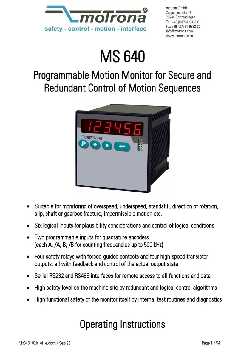
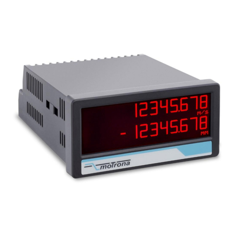
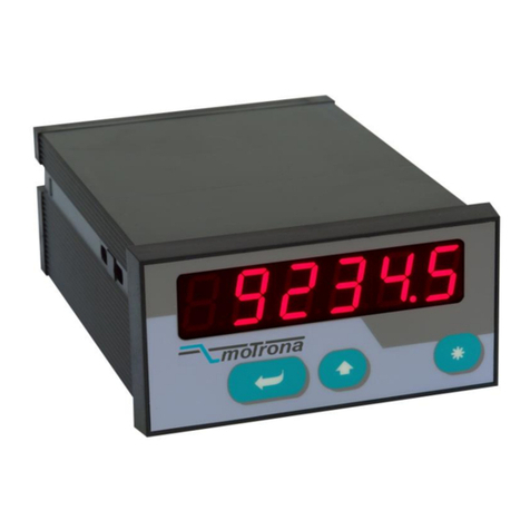
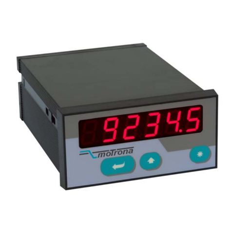
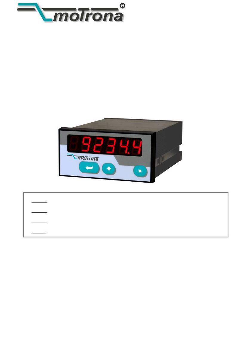
Motrona SD Series User manual

control – motion – interface
motrona GmbH
Zwischen den Wegen 32
78239 Rielasingen - Germany
Tel. +49 (0)7731-9332-0
Fax +49 (0)7731-9332-30
www.motrona.com
SD34002g_e.doc / Sep-13 Page 1 / 60
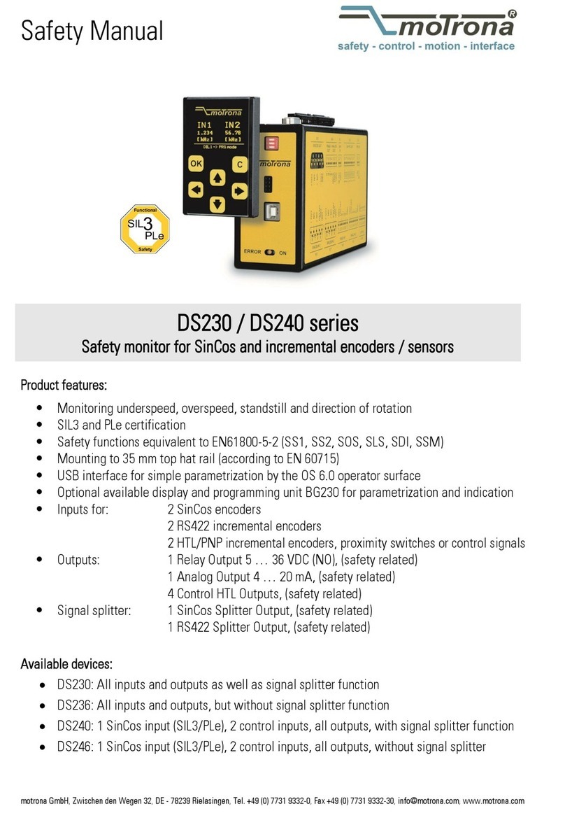
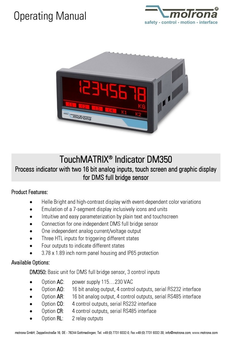
Series SD / SA / SR 330 - 644
Advanced Measurement of RPM, Speeds,
Baking and Processing Times, Speed Ratios,
Sum or Differential Speeds
Series SD: 4 programmable presets and outputs, RS 232 interface
Series SA: 4 programmable presets and outputs, RS 232 interface and analogue output
Series SR: 4 programmable presets and outputs, RS 232 interface and RS485 interface
Simultaneous measuring of two independent speeds by means of incremental
encoders, proximity switches or photocells
Two encoder inputs for use with 1 or 2 or 4 channels (A, /A, B, /B), each with
1 MHz of counting capability and individual scaling
Selectable operating modes for RPM, speed, baking time (reciprocal speed),
summing or differential speed, speed ratios and percentaged difference
4 speed presets with high-speed power transistor outputs
Models with relay outputs or front thumbwheel switches are available
Operating Instructions

SD34002g_e.doc / Sep-13 Page 2 / 60
Safety Instructions
This manual is an essential part of the unit and contains important hints about
function, correct handling and commissioning. Non-observance can result in
damage to the unit or the machine or even in injury to persons using the
equipment!
The unit must only be installed, connected and activated by a qualified electrician
It is a must to observe all general and also all country-specific and application-
specific safety standards
When this unit is used with applications where failure or maloperation could cause
damage to a machine or hazard to the operating staff, it is indispensable to meet
effective precautions in order to avoid such consequences
Regarding installation, wiring, environmental conditions, screening of cables and
earthing, you must follow the general standards of industrial automation industry
- Errors and omissions excepted –
General instructions for cabling, screening and grounding can be found in the
SUPPORT section of our website http://www.motrona.com
Version:
Description:
SD34002a/Mrz10/af/hk
First final sales version
SD34002b/Dez11
/sm
conformation
of the type designation
SD3
4
002c/Feb12/sm
Correction of the parameter
-
values and code listings
.
Parameter listing for SD/SA/SR x3x added.
S
D34002
d/June12/pp
Corrected images in chapter 1 and 8.2
S
D34002e
/
Sept
12/pp
Correction of examples
for parameter
F06.075
SD34002f/Jan13/af/nw
Correction of parameter
F03.030, F04.042
and F06.066
SD34002g/
S
ep
t
13/tj/nw
Extension: Advice for encoder inputs

SD34002g_e.doc / Sep-13 Page 3 / 60
Table of Contents
1. Available Models................................................................................................................4
2. Introduction.........................................................................................................................6
3. Electrical Connections.........................................................................................................7
3.1. Power Supply................................................................................................................................9
3.2. Auxiliary Outputs for Encoder Supply ..........................................................................................9
3.3. Impulse Inputs for Incremental Encoders.....................................................................................9
3.4. Control Inputs Cont.1 – Cont.4.....................................................................................................9
3.5. Switching Outputs K1 – K4 ........................................................................................................10
3.6. Serial Interface ...........................................................................................................................10
3.7. Fast Analogue Output (SA models only) ....................................................................................10
4. Operating Modes of the Counter.......................................................................................11
4.1. “Single Mode” (encoder 1 only): F02.004 = 0 ............................................................................13
4.2. Dual Mode (encoder1 and encoder 2 independently): F02.004 = 1...........................................14
4.3. Sum Mode (encoder 1 + encoder 2): F02.004 = 2 ......................................................................15
4.4. Differential Mode (encoder 1 - encoder 2): F02.004 = 3............................................................16
4.5. Product of Two Speeds (encoder 1 x encoder 2): F02.004 = 4...................................................17
4.6. Ratio of two Speeds: F02.004 = 5 or 6.......................................................................................18
4.7. Percentaged Speed Difference: F02.004 = 7 or 8 ......................................................................19
5. Keypad Operation .............................................................................................................20
5.1. Normal Operation .......................................................................................................................20
5.2. General Setup Procedure............................................................................................................20
5.3. Direct Fast Access to Presets.....................................................................................................21
5.4. Change of Parameter Values on the Numeric Level..................................................................22
5.5. Code Protection against Unauthorized Keypad Access.............................................................23
5.6. Return from the Programming Levels and Time-Out Function ..................................................23
5.7. Reset all Parameters to Factory Default Values........................................................................23
6. Menu Structure and Description of Parameters ................................................................24
6.1. Summary of the Menu................................................................................................................24
6.2. Description of the Parameters ...................................................................................................27
7. Practical Examples for Setup and Scaling .........................................................................44
7.1. Settings for the Example a) of Chapter 4.1 (Speed Display) .....................................................44
7.2. Settings for the Example b) of Chapter 4.1 (Baking Time).........................................................44
7.3. Settings for Example "Differential Speed" of Chapter 4.4 ........................................................45
7.4. Example for Use of the Filter......................................................................................................46
8. Appendix for models SD/SA/SR 6xx .................................................................................47
8.1. Relay Outputs .............................................................................................................................47
8.2. Front Thumbwheel Switches......................................................................................................47
8.3. Specific Parameters for Units with Thumbwheel Switches......................................................48
9. Appendix: Serial Communication Details ..........................................................................50
9.1. Setup of the Counter by PC ........................................................................................................50
9.2. Automatic and Cyclic Data Transmission ..................................................................................51
9.3. Communication Protocol.............................................................................................................51
9.4. Serial Register Codes .................................................................................................................53
10. Specifications ...................................................................................................................58
11. Dimensions.......................................................................................................................59
SD34002g_e.doc / Sep-13 Page 4 / 60
1. Available Models
The speed meters of this series include a range of models with similar functions and properties,
but with different housings, outputs and interfaces.
All models are equipped with 4 programmable presets and 4 fast-switching transistor outputs
as well as a serial RS232 interface.
SD models provide this basic configuration only.
SA models provide an additional high-speed analogue output
SR models provide an additional RS485 communication interface
All further properties of the models are fully identical. The range of available models also
includes units with relay outputs and front thumbwheel switches.
The following table explains the details of type designation and the possible options:
S = speed meter
D = display and RS232 interface
A = display, RS232 interface and analogue output
R = display, RS232 interface and RS485 interface
3 = housing 96 x 48 mm (3.780 x 1.890’’)
and 4 high-speed transistor outputs
6 = housing 96 x 96 mm (3.780 x 3.780’’)
with 4 high-speed transistor outputs
and 4 relay outputs
0 = no thumbwheel switches on front
2 = two thumbwheel sets (4 decades each) *)
4 = four thumbwheel sets (4 decades each) *)
SD 340
*) Other combinations are possible, see section 8.2

SD34002g_e.doc / Sep-13 Page 5 / 60
The following models are available:
SD 340, SA 340, SR 340
SD 640, SA 640, SR 640
SD 642, SA 642, SR 642
SD 644, SA 644, SR 644
Number and combination of front thumbwheels according to customer specification, see section 8.2

SD34002g_e.doc / Sep-13 Page 6 / 60
2. Introduction
Speed meters of series SD, SA and SR have been designed to close a gap with multiple speed
measuring applications, which cannot be accomplished by normal industrial tachometers.
A continual demand for increasing production speeds and higher precision at the same time
results in counting frequencies exceeding the conventional frequency range.
Particularly with fast running machines it is most important to also get fast response of the
switching outputs or the analogue output.
Many applications require to evaluate the signals of two incremental measuring systems, and
to compare the results with respect to the sum or the difference or the ratio of the two speeds.
The latter is e.g. required to indicate the diameter of a winding roll by sensing the line speed
and the roll rpm.
Other applications with food processing or process technology need to record the speed in a
reciprocal way (i.e. baking or processing time calculated from the actual speed)
And still there exist applications where the use of traditional thumbwheel switches offers real
advantages compared to keypad and menu operations.
These are some of the reasons why the new indicator series SD / SA / SR have been designed.
This manual at first provides all basic instructions for operation of the
counter models presented in the previous chapter
For operation of relay outputs and thumbwheel switches (if applicable)
please observe the supplementary instructions given in the appendix
For easy PC setup and PC communication with SD and SA counters,
please use our “OS32” operator software (free of charge, download from
our homepage www.motrona.com
Where you like to have free serial access to the unit by PLC or IPC or by a
remote operator terminal, please observe the serial protocol details
described in our separate manual “Serpro”
Subsequently the manual uses the expression SD340 as a replacement for
all available models. However, statements are fully valid for the other
models too, except where especially remarked.

SD34002g_e.doc / Sep-13 Page 7 / 60
3. Electrical Connections
17 18 19 20 21 23 24 25 26
27
28
29
30
31
32
1 2 3 4 5 6 7 8 9 10 11 12
13
14
15
16
G
N
D
G
N
D
G
N
D
G
N
D
G
N
D
+
V
i
n
+
5
,
2
V
a
u
x
.
o
u
t
+
5
,
2
V
a
u
x
.
o
u
t
+
2
4
V
a
u
x
.
o
u
t
+
2
4
V
a
u
x
.
o
u
t
E
n
c
o
d
e
r
2
B
E
n
c
o
d
e
r
2
A
E
n
c
o
d
e
r
1
B
E
n
c
o
d
e
r
1
A
E
n
c
o
d
e
r
1
/
A
E
n
c
o
d
e
r
1
/
B
E
n
c
o
d
e
r
2
/
A
E
n
c
o
d
e
r
2
/
B
K
2
o
u
t
K
1
o
u
t
K
3
o
u
t
K
4
o
u
t
Cont. 1
Cont. 2
C
o
n
t
.
4
C
o
n
t
.
3
Com+ (K1-K4)
TxD (RS232)
I
n
t
e
r
f
a
c
e
2
*
)
I
n
t
e
r
f
a
c
e
1
*
)
R
x
D
(
R
S
2
3
2
)
P
R
O
G
X1
X2
+5
-
A
/A
B
/B
+5
-
A
/A
B
/B
Encoder1*
Encoder 2*
Cont1
Cont2
Cont3
Cont4
Digital
Control
Inputs
RxD
TxD
GND
RS232
-
+
24 V DC
Power supply
Com+ (K1 - K4)
K1 out
K2 out
K3 out
K4 out
Fast
transistor
outputs
+24
+24
0V, GND
PROG
18
24
23
20
19
22
21
11
12
6
5
27
28
30
3
31
17
1
4
29
26
25
7
8
32
2
16
Interface 2 *)
15
14
13
10
9
24 V AC
*) Example shows wiring
for encoders with 5 volts
power supply and RS422
line driver output
Interface 1 *)
Series "SD"
Series "SA"
Series "SR"
*) Interface 1:
- n.c. - Analogue output 0/4 - 20 mA RS 485, B (-)
*) Interface 2:
- n.c. - Analogue output +/- 10 V RS 485, A (+)

SD34002g_e.doc / Sep-13 Page 8 / 60
Terminal
Name
Function
01
GND
Common Ground Potential (0V)
02
+5,2V out
Aux. output 5.2V/150 mA for encoder
supply
03
+24V out
Aux. output 24V/120 mA for encoder
supply
04
GND
Common Ground Potential (0V)
05
Encoder 2, /B
Encoder 2, chann
el /B (B inverted)
06
Encoder 2, /A
Encoder 2, channel /A (A inverted)
07
Encoder 1, /B
Encoder 1, channel /B (B inverted)
08
Encoder 1, /A
Encoder 1, channel /A (A inverted)
09
K4 out
Output K4, transistor PNP 30 volts, 350 mA
10
K3 out
Output K3, tr
ansistor PNP 30 volts, 350 mA
11
Cont.4
Digital control input
12
Cont.3
Digital control input
13
(PROG)
(for download of new firmware only, not for general use)
14
RxD
Serial RS232 interface, input (Receive Data)
15
Interface 1
SD 340: n.c. (no function)
SA 340: Analogue current output 0/4 - 20 mA
SR 340: Serial RS385 interface, line B (-)
16
Interface 2
SD 340: n.c. (no function)
SA 340: Analogue voltage output +/- 10 V
SR 340: Serial RS485 interface, line A (+)
17
+Vin
Power supply input, +17
–
40 VDC or 24 VAC
18
+5,2V out
Aux. output 5,2V/150 mA for encoder
supply
19
+24V out
Aux. output 24V/120 mA for encoder
supply
20
GND
Common Ground Potential (0V)
21
Encoder 2, B
Encoder 2, channel B (non
-
inverted
)
22
Encoder 2, A
Encoder 2, channe
l A (non
-
inverted
)
23
Encoder 1, B
Encoder 1, channel B (non
-
inverted
)
24
Encoder 1, A
Encoder 1, channel A (non
-
inverted
)
25
K2 out
Output K2, transistor PNP 30 volts, 350 mA
26
K1 out
Output K1, transistor PNP 30 volts, 350 mA
27
Cont.2
Digital cont
rol input
28
Cont.1
Digital control input
29
Com+ (K1
-
K4)
Common positive input for transistor outputs K1
-
K4
30
TxD
Serial RS232 interface, output (Transmit Data)
31
GND
Common Ground Potential (0V)
32
GND
Common Ground Potential (0V) for DC or AC pow
er supply
*) 120 mA and 150 mA are per encoder, i.e. total maximum currents are 240 mA and 300 mA

SD34002g_e.doc / Sep-13 Page 9 / 60
3.1. Power Supply
The SD340 counter accepts both, a 17 – 40 volts DC power or a 24 volts AC power (+/-10%)
for supply via terminals 17 and 1. The current consumption depends on the level of the input
voltage and some internal conditions; therefore it can vary in a range from 100 – 200 mA
(aux. currents taken from the unit for encoder supply not included).
3.2. Auxiliary Outputs for Encoder Supply
Terminals 2 and 18 provide an auxiliary output with approx. +5.2 volts DC (300 mA totally).
Terminals 3 and 19 provide an auxiliary output with approx. +24 volts DC (240 mA totally)
3.3. Impulse Inputs for Incremental Encoders
All input characteristics of the impulse inputs can be set by the parameter menu, for each of
the encoders separately. Depending on the application the unit can accept single channel
information (input A only without direction signal) or dual channel signals (A = step and B =
direction) or quadrature information (A / B, 90°). The following settings are possible:
Symmetric input (differential A, /A, B, /B) according to RS422 standard
TTL inputs at a level of 3.0 to 5 volts (differential, with inverted signal)
TTL inputs at a level of 3.0 to 5 volts (single-ended) *)
HTL signals at a 10 – 30 volts level
(alternatively differential with inverted signals A, /A, B, /B, or single-ended A, B only)
Impulses from photocells or proximity switches etc. providing a HTL level (10 – 30 volts)
Proximity switches according to NAMUR (2-wire) standard
(may need additional remote resistor)
*) requires special settings of the threshold parameters, see “Special parameters F08”
All encoder input lines are internally terminated by pull-down resistors ( 8,5 kΩ).
Where encoders with pure NPN outputs are used, corresponding pull-up resistors must be
available inside the encoder or externally to ensure proper function (1 kΩ... 3,3 kΩ).
3.4. Control Inputs Cont.1 – Cont.4
These inputs can be configured for various remote functions as described under 6.2.4.
All control inputs require HTL level. They can be individually set to either NPN (switch to -) or
PNP (switch to +) characteristics. For applications where edge-triggered action is needed, the
menu allows to set the active edge (rising or falling). Control inputs also accept signals with
Namur (2-wire) standard.
For reliable operation the minimum pulse width on the control inputs should be 50 µsec.

SD34002g_e.doc / Sep-13 Page 10 / 60
3.5. Switching Outputs K1 – K4
SD340 provides four presets and outputs with programmable switching characteristics.
K1 – K4 are fast-switching and short-circuit-proof transistor outputs with a switching capability
of 5 – 30 volts / 350 mA each. The switching voltage of the outputs must be applied remotely
to the Com+ input (terminal 29)
3.6. Serial Interface
The serial RS232/RS485 interfaces can be used for the following purposes:
Set-up of the unit by PC (if desirable), by means of the OS32 PC software
Change of parameters during operation
Readout of actual counter or other values by PLC or PC
The figure below explains how to connect the SD340 unit and a PC using the standard Sub-D-9
serial connector, and how to connect the RS485 terminals to a PLC.
Details about serial communication are shown in chapter 9.
2
3
5
RxD RxD
TxDTxD
GND
Screen
PC
SD 340
SA 340
SR 340
14
(Sub-D-9)
30
31
RS 232
PLC
SR 340 16
15
RS 485
A(+)
B(-)
A
B
Where both, RS232 and RS485 interface are in use, you can communicate by the one or
by the other, but not by both interfaces at the same time
3.7. Fast Analogue Output (SA models only)
An analogue output is available with all SA models, providing a voltage output of +/- 10 volts
(Load = 2 mA), and a current output of 0 – 20 mA or 4 – 20 mA (load = 0 – 270 Ohms). All output
characteristics like beginning of conversion range, output swing etc. are freely programmable
via menu. The response time of the analogue output depends on the mode of measuring and
the sampling times used. The analogue resolution is 14 bits.
Please note that extensive serial communication with the unit may temporary increase the
analogue response time.

SD34002g_e.doc / Sep-13 Page 11 / 60
4. Operating Modes of the Counter
For best survey, all parameters of the unit are arranged in 13 expedient groups, named
“F01” - “F13”. Depending on the application, only a few of these groups may be important,
while all other groups may be irrelevant for your specific application.
All details about configuration and function of the parameters can be founds in chapter 6.
Practical examples for settings are shown in chapter 7.
This section describes possible applications and operating modes of the unit.
The operation mode can be set under parameter group F02, parameter # F02.004.
It is possible to cycle the display between all reading modes shown in the following
function tables, by pressing one of the front keys or by using one of the control inputs
(you must have assigned the "display scrolling function" to one of the keys or the
inputs under menu F05 to activate the scrolling of the display).
LED L1 (red) and L2 (yellow) indicate which of the values is actually visible in display
L1 on: the speed of encoder 1 is displayed
L2 on: the speed of encoder 2 is displayed
L1 and L2 on: the combined value [encoder1]*[encoder2] is displayed.
LEDs shining continuously indicate: actual measuring value.
LEDs blinking slowly indicate: minimum value
(since last reset of the min/max memory).
LEDs blinking fast indicate: maximum value (since last reset of the min/max memory).
Scrolling of the display from one reading mode to another will not affect the function
of the preselection outputs K1 – K4
The analogue output (models SA) can be assigned to any of the readings accessible in
the display, by a special parameter. Scrolling of the display from one reading mode to
another will not affect the analogue output.
With all operating modes the evaluation of the input frequencies occurs fully
separately with use of individual scaling factors. Please observe that only integer
results after the scaling operations, but no decimal positions will appear in the
display. Where you like to display your result with decimals, please scale your value
correspondingly higher (by factor 10, 100 or 1000) and then use a decimal point to
receive the desired display value (see examples under 7.1)
With all encoders providing information about the direction of rotation
(e.g. quadrature encoders A/B/90°), the unit will also display a sign (positive with
A leading B and negative with B leading A). Preselection values can be set for
response to absolute values only (no consideration of the actual sign), or for response
to the signed value. With models SA the analogue output will also change the
+/- polarity in accordance with the actual sign.
All combinations [encoder1] * [encoder2] are calculated straightaway according to the
individual operating mode and the scaling factor of each channel. Please take care
that the results to combine are scaled with proper and compatible dimensions
(don't compare apples and oranges)

SD34002g_e.doc / Sep-13 Page 12 / 60
You can choose from the following operating modes:
Operating Mode
F02.004 Measuring Function of the unit
0
Single mode, evaluation of encoder 1 only
1
Dual mode, individual evaluation of encoder 1 and encoder 2
2
Sum mode, [speed of encoder1] + [speed of encoder2]
3
Differential mode, [speed of encoder1]
-
[speed of encoder2]
4
Multipl
ication mode, [speed of encoder1] x [speed of encoder2]
5
Ratio mode, [speed of encoder1] : [speed of encoder2]
6
Inverse ratio mode, [speed of encoder2] : [speed of encoder1]
7
Percentage mode, [encoder1
-
encoder2] : [encoder2] x 100%
8
Inverse perce
ntage mode, [encoder2
-
encoder1] : [encoder1] x 100%
Your choice of operating mode will decide how in general the two encoder frequencies have to
be treated. It will not affect the scaling or the measuring characteristics or the final
presentation of the result.

SD34002g_e.doc / Sep-13 Page 13 / 60
4.1. “Single Mode” (encoder 1 only): F02.004 = 0
Only the inputs of encoder 1 are active, signals on the encoder 2 inputs will not be evaluated.
Besides the actual counter value, the unit also records minimum and maximum values, with
regard to the last Reset of the Min/Max memory.
All 4 presets are related to the actual measuring value.
Display
L1 (red)
L2 (yellow)
1
Actual measuring value of encoder 1
statically ON
--
2
Minimum value since last min/max reset
blinking slow
--
3
Maximum value s
ince last min/max reset
blinking fast
--
Measuring wheel
Encoder
Encoder 1
- 3 4 5 6
Cont.1 Cont.4
Encoder 2
Remote control signals
f1
Example a): Measuring of RPM or speed *)
Proximity
sensor
°C
Tunnel furnace
Speed-variable
motor
Calculated baking time
Example b): Measuring of baking time or processing time (reciprocal speed) *)
*) For these applications you can find concrete examples of parameter settings in chapter 7.

SD34002g_e.doc / Sep-13 Page 14 / 60
4.2. Dual Mode (encoder1 and encoder 2 independently): F02.004 = 1
Both, encoder input 1 and encoder input 2 are active and the frequencies are evaluated
independently,
Besides the actual measuring values the unit also records the minimum and maximum values of
both channels, with regard to the last Reset of the Min/Max memory.
Presets K1 and K2 refer always to the measuring result of encoder 1.
Presets K3 and K4 refer always to the measuring result of encoder 2.
Display
L1 (red)
L2 (yellow)
1
Actual measuring value of encoder 1
statically ON
2
Minimum value encoder 1 since last min/max reset
blinking slow
3
Maximum value encoder 1 since last min/max reset
blinking fast
4
Actual measuring value of encoder 2
statically ON
5
Minimum value encoder 2 since last min/max reset
blinking slow
6
Maximum value encoder 2 since last min/max reset
blinking fast
Geber 1
1 2 3 4 5 6
Cont.1 Cont.4
Geber 2
---
Remote control functions
Products per minute (p)Motor speed (rpm)
Example: Dual speed application with selectable display of motor speed (rpm) and product throughput (p)

SD34002g_e.doc / Sep-13 Page 15 / 60
4.3. Sum Mode (encoder 1 + encoder 2): F02.004 = 2
Both inputs, encoder 1 and encoder 2, are active. From both values the unit forms the sum, with
consideration of the individual scaling of each channel. The final result can once more be
scaled into user-friendly engineering units by means of the special scaling parameters in
parameter group F02.
Besides the actual speeds and the sum value, the unit also records minimum and maximum
values of the sum.
Preset K1 is related to the absolute speed of encoder 1.
Preset K2 is related to the absolute speed of encoder 2.
Presets K3 and K4 are related to the actual sum of the speeds (encoder 1 + encoder 2)
Display
L1 (red)
L2 (ye
llow)
1
Actual sum [speed encoder1] + [speed encoder2]
statically ON
statically ON
2
Minimum sum value since last min/max reset
blinking slow
blinking slow
3
Maximum sum value since last min/max reset
blinking fast
blinking fast
4
Actual measuring valu
e of encoder 1
statically ON
---
5
Actual measuring value of encoder 2
---
statically ON
Encoder 1 Encoder 2
123456
2 x incremental flow sensors
Q1Q2
Example: Summing flow Q1+ Q2(liters per minute) of two incremental rotary flow sensors

SD34002g_e.doc / Sep-13 Page 16 / 60
4.4. Differential Mode (encoder 1 - encoder 2): F02.004 = 3
Both inputs, encoder 1 and encoder 2, are active. From both values the unit forms the
difference, with consideration of the individual scaling of each channel. The final result can
once more be scaled into user-friendly engineering units by means of the special scaling
parameters in parameter group F02.
Besides the actual speeds and the differential value, the unit also records minimum and
maximum values of the speed difference.
Preset K1 is related to the absolute speed of encoder 1.
Preset K2 is related to the absolute speed of encoder 2.
Presets K3 and K4 are related to the actual differential speed (encoder 1 - encoder 2)
Display
L1 (red)
L2 (yellow)
1
Speed difference [speed encoder1]
-
[speed encoder2]
statically
ON
statically ON
2
Minimum difference since last min/max reset
blinking slow
blinking slow
3
Maximum difference since last min/max reset
blinking fast
blinking fast
4
Actual measuring value of encoder 1
statically ON
---
5
Actual measuring value of enc
oder 2
---
statically ON
Encoder 1
- 3 4 .5 6
Cont.1 Cont.4
Encoder 2
Remote control functions
speed 1 speed 2
Example: Differential speed of two belt conveyors

SD34002g_e.doc / Sep-13 Page 17 / 60
4.5. Product of Two Speeds (encoder 1 x encoder 2): F02.004 = 4
Both inputs, encoder 1 and encoder 2, are active. Both speeds are multiplied to form the
product, with consideration of the individual scaling of each channel. The final result can once
more be scaled into user-friendly engineering units by means of the special scaling parameters
in parameter group F02.
Besides the actual speeds and the multiplication result, the unit also records minimum and
maximum values of the product.
Preset K1 is related to the absolute speed of encoder 1.
Preset K2 is related to the absolute speed of encoder 2.
Presets K3 and K4 are related to the product of both speeds (encoder 1 x encoder 2)
Display
L1 (red)
L2 (yellow)
1
Speed product [speed encoder1] x [speed encoder2]
statically ON
statically ON
2
Minimum product since last min/max reset
blinking slow
blinking slow
3
Maximum product sin
ce last min/max reset
blinking fast
blinking fast
4
Actual measuring value of encoder 1
statically ON
---
5
Actual measuring value of encoder 2
---
statically ON
v (speed)
m
(mass)
Geber 1
Cont.1 Cont.4
Geber 2
W = 1/2 m v
2
Example: Direct measurement of the kinetic energy "W" of a moving body with the mass "m"

SD34002g_e.doc / Sep-13 Page 18 / 60
4.6. Ratio of two Speeds: F02.004 = 5 or 6
Both inputs, encoder 1 and encoder 2, are active. The unit calculates the ratio of the two
speeds, with consideration of the individual scaling of each channel. The final result can once
more be scaled into user-friendly engineering units by means of the special scaling parameters
in parameter group F02 (conversion factor K = F02.09 : F02.08), see figure below*).
F02.004 = 5 calculates [encoder1] : [encoder2]
F02.004 = 6 calculates [encoder2] : [encoder1]
Besides the actual speeds and the ratio the unit also records minimum and maximum values of
the ratio.
Preset K1 is related to the absolute speed of encoder 1.
Preset K2 is related to the absolute speed of encoder 2.
Presets K3 and K4 are related to the ratio of both speeds
Display
L1 (red)
L2 (yellow)
1
Speed ratio [encoder
(1 or 2)
] : [encoder
(2 or 1)
] *)
statically ON
statically ON
2
Minimum ratio since last min/max reset
blinking slow
blinking slow
3
Maximum rat
io since last min/max reset
blinking fast
blinking fast
4
Actual speed of encoder 1
statically ON
---
5
Actual speed of encoder 2
---
statically ON
Encoder 1
1 2 3 4 5 6
Cont.1 Cont.4
Encoder 2
Remote control functions
d
Roll diameter
f1f2d = K x f2
f1
Example: Calculation of the roll diameter "d" from the ratio of infeed speed and roll rpm
*) The unit presents the ratio of the two speeds as an integer number only, e.g. if both speeds are equal,
the unit would just display "1". To display a ratio with decimal positions like 1.0 or 1.00 or 1.000 etc. it
is necessary to follow one of these hints:
a. scale the speed used as numerator by a factor of 10 or 100 or 1000 higher than the denominator, or
b. set parameters F02.009 (multiplier) and F02.008 (divider) with a ratio of 10, 100 or 1000

SD34002g_e.doc / Sep-13 Page 19 / 60
4.7. Percentaged Speed Difference: F02.004 = 7 or 8
Both encoder inputs "encoder1" and "encoder2" are active. With consideration of the individual
scaling of each channel the unit calculates the percentaged difference as shown below:
F02.004 = 7:
Display =
[ speed of encoder 1 ] -
[ speed ofencoder 2 ]
[ speed of encoder 2 ] x 100%
F02.004 = 8:
Display =
[ speed of encoder 2 ] -
[ speed ofencoder 1 ]
[ speed of encoder 1 ] x 100%
Parameter „Percent Format“ (F02.018) determines the number of decimal positions of the result:
0 = display range -999999 to + 9999999 % 1 = display range -99999,9 to +99999,9 %
2 = display range -9999,99 to +9999,99 % 3 = display range -999,999 to +999,999 %
The final percentage result can once more be scaled into user-friendly engineering units by
means of the special scaling parameters in parameter group F02
Besides the actual speeds and the ratio the unit also records minimum and maximum values of
the ratio.
Preset K1 is related to the absolute speed of encoder 1.
Preset K2 is related to the absolute speed of encoder 2.
Presets K3 and K4 are related to the percentaged difference of both speeds
Display
L1 (red)
L2 (yellow)
1
Actual percentage difference
statically ON
statically ON
2
Minimum percentage since last min/max reset
blinking slow
blinking slow
3
Maximum percentage since last min/max reset
blinking fast
blinking fast
4
Actual speed
of encoder 1
statically ON
---
5
Actual speed of encoder 2
---
statically ON
Encoder 1
Cont.1 Cont.4
Encoder 2
Remote control functions
f
1
f
2
tension
speed 1
speed 2
speed 2 > speed 1
Example: stretching of material by building up tension

SD34002g_e.doc / Sep-13 Page 20 / 60
5. Keypad Operation
An overview of all parameters and explanations can be found under section 6.
The menu of the unit uses four keys, hereinafter named as follows:
PROG
UP
DOWN
ENTER
Key functions depend on the actual operating state of the unit. Essentially we have to describe
three basic states:
Normal operation
General setup procedure
Direct fast access to presets and set values
5.1. Normal Operation
In this mode the unit operates as a counter according to the settings defined upon setup. All
front keys may have customer-defined functions according to the specifications met in the
keypad definition menu F05 (e.g. scrolling of the display, Reset, Inhibit etc.)
5.2. General Setup Procedure
The unit changes over from normal operation to setup level when keeping the key down
for at least 2 seconds. Thereafter you can select one of the parameter groups F01 to F13.
Inside the group you can now select the desired parameter and set the value according to need.
After this you can either set more parameters or return to the normal operation.
The adjoining sequence of key operations explains how to change
Parameter number 060 of group F06 from the original value of 0 to 8
P
This manual suits for next models
17
Table of contents
Other Motrona Measuring Instrument manuals

Motrona
Motrona DX350 User manual

Motrona
Motrona AX 342 User manual

Motrona
Motrona AX020 User manual

Motrona
Motrona AX 346 User manual

Motrona
Motrona IX 345 User manual

Motrona
Motrona AX320 User manual

Motrona
Motrona IX348 User manual

Motrona
Motrona touchMATRIX MX350 User manual

Motrona
Motrona DS230 Series User guide

Motrona
Motrona touchMATRIX DP350 User manual