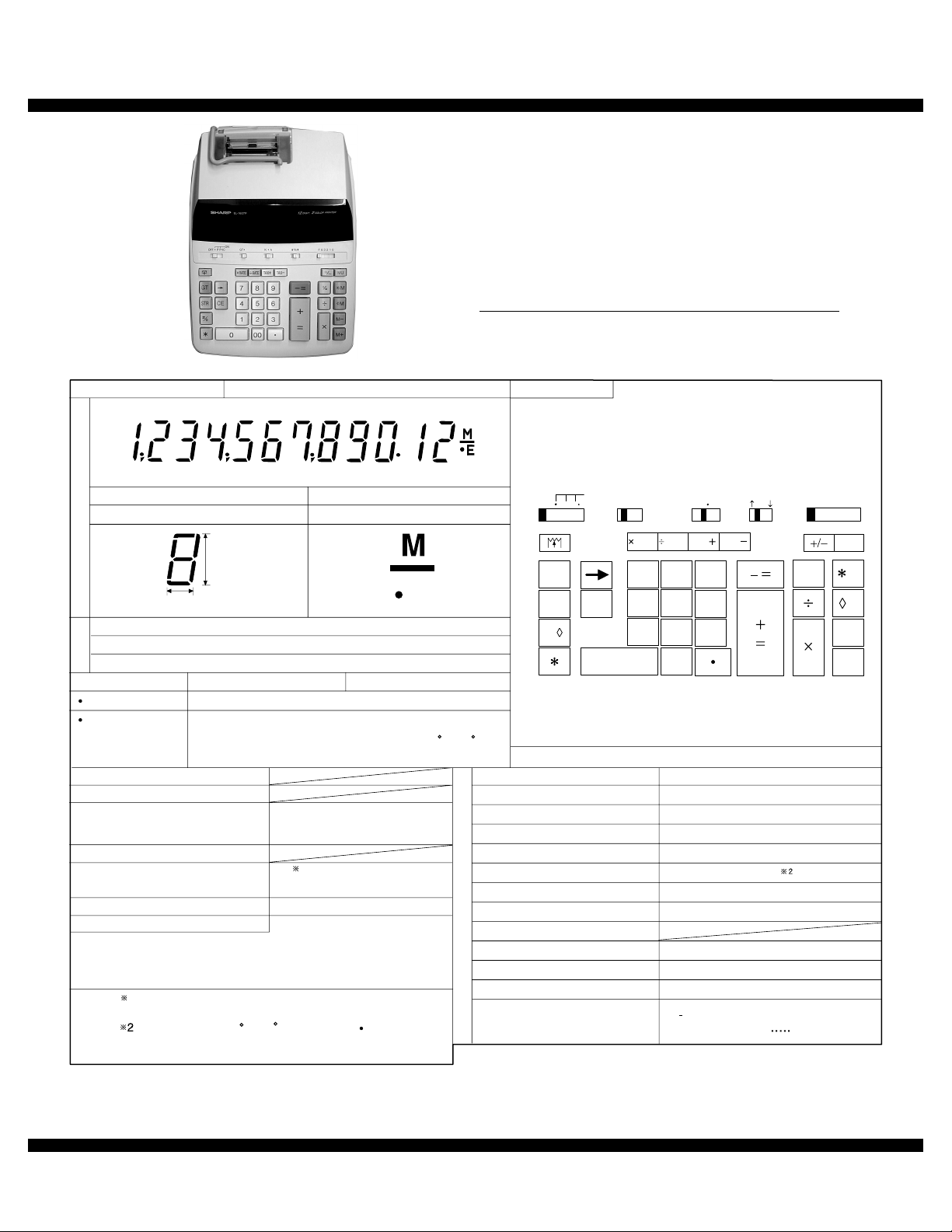
Sharp EL-1607P User manual

CODE : 00ZCODE : 00Z
qSERVICE MANUAL
Parts marked with "!" are important for maintaining the safety of the set. Be sure to replace these parts with specified
ones for maintaining the safety and performance of the set.
SHARP CORPORATION
This document has been published to be used for
after sales service only.
The contents are subject to change without notice.
EL1607P/2E
MODEL EL-1607P
STANDARD FUNCTION 12 digits 1 M
ELEMENT: Display tube
NUMERAL: 12
Name : U3866-ZE731
Type : COB
Pin : 76 Pins
PARTS NAME:
SYMBOL: 1 digit (s)
D
I
S
P
L
A
Y
S
E
C
T
I
O
N
P
R
I
N
T
E
R
S
E
C
T
I
O
N
L
S
I
POWER SUPPLY
AC ADAPTOR
RECHARGEABLE BATTERY
POWER CONSUMPTION
AUTO POWER OFF TIME
MEMORY PROTECT
MODEL NAME
PRINTING SYSTEM
PRINTING CAPACITY
CHARACTER DIMENSION
INPUT BUFFER
PRINTING SPEED
PAPER FEED SPEED
PAPER RELEASE MECHANISM
INK RIBBON
INK ROLLER (OPTION)
INK LIFE
PAPER
PTMFL87 (KI-OB1078CCZZ)
Serial print type
19 digits
1.6 (W) 3.5 (H) mm
12 stages
Approx. 3.0 lines/sec
Approx. 8.5 lines/sec
Yes (Forward only)
Plain paper
58 mm (W), 80 mm in diameter
DPAPR1004CSZZ 5rolls/pack
PAPER SIZE (Roll paper)
DIMENSIONS (mm)
Yes 1
(TAX/Discount rate/Conversion rate)
220 (W) 303 (D) 71.5 (H)
220-230V: 48mA
230-240V: 48mA
Multi : 8.1W
CALCULATIONS
BATTERY TYPE AC only
CR2032 x 1pc
Approx. 2 years. (tested and confirmed at 25 C (77 F);
may change due to usage environment)
MEMORY
PROTECTION
BATTERY
(ACO only)
AC: oDC: u
Four arithmetic calculations, Constant calculation, Power
calculation, Chain calculation, Reciprocal calculation, %
calculation, Add-on (discount) calculation. Grand total
calculation, etc.
Note) 1: Enable only when power is supplied from
the power cord or the backup battery.
E
KEY LAYOUT
KEY SYSTEM: Resin key Top + Rubber
(mm)
12.0
4.1
+0
1
digits
13-LT-47GN
5/4
3210
FA
6
GT
OFF P P IC
ON
8
00
2
5
9
3
6
0
1
4
7
CE
GT
STR
#/
%M
M
−
M
+
M
KA
MU
RATE TA X TA X
RATE
At temperature 25 C (77 F), when "951 +" is printed.
The printing speed will vary with the number of rows
and the figure types to be printed.
:
Black : EA-781R-BK, Red : EA-781R-RD
200 thousand characters
(AAC,ACO,ABC,TRC)

EL-1607P Block diagram
– 2 –
1. Block diagram 2. Power voltage
*Measure with the rated AC input voltage.
• MEASURING PIN POSITION
3. Ink roller replacement
If printing is blurry even when the ink roller is in the proper position,
replace the roller.
Ink roller:Type EA-781R-BK (Black)
Type EA-781R-RD (Red)
WARNING:
1. Set the power switch to OFF.
2. Remove the printer cover.
3. Remove the ink roller by turning it counterclockwise and pulling it
upward.
4. Install the correct color new ink roller and press it in the correct
position. Make sure that the ink roller is securely in place.
㧔㧦Power supply line㧕
㧔㧦Signal line㧕
L S I KEY/SL-SW
PRINTER
Display tube
AC input
VFD DRIVER
AC
transfomer
Power supply
Circuit
P/H DRIVER
( )BATT.
()ACO only
*
*
Measurement point Power voltage
F1 - F2 4.0 VAC ~ 4.4 VAC
VSS - VDD
VSS - VCC 4.5 VDC ~ 5.5 VDC
F2
F1
F1
VCCVSSVDD
F2
APPLYING INK TO WORN INK ROLLER OR USE OF UNAP-
PROVED INK ROLLER MAY CAUSE SERIOUS DAMAGE TO
PRINTER.
Blac
k
Red

EL-1607P Paper roll replacement
–3 –
5. Put back the printer cover.
Cleaning the printing mechanism
If the print become dull after long time usage, clean the printing
wheel according to the following procedures:
1. Remove the printer cover and the ink roller.
2. Install the paper roll and feed it until it comes out of the front of the
printing mechanism.
3. Put a small brush (like a tooth brush) lightly to the printing
wheel and clean it by pressing .
4. Put back the ink roller and the printer cover.
Note: •Never attempt to turn the printing belt or restrict its movement
while printing. This may cause incorrect printing.
•Do not rotate the printing mechanism manually, this may dam-
age the printer.
4. Paper roll replacement
Never insert paper roll if torn. Doing so will cause paper to jam.
Always cut leading edge with scissors first.
1. Insert the leading edge of the paper roll into the opening.
2. Turn the power on and feed the paper by pressing .
3. Lift the attached metal paper holder up and insert the paper roll to
the paper holder.
5. Replacement of battery for memory
protection (for EL-1607P (ACO))
Time for battery replacement
Replace with a new battery once 2 year.
Method of battery replacement
Use one lithium battery (CR2032).
Note: When replacing the battery, the set tax/discount rate and conver-
sion rate, the memory contents will be lost.
You may want to write down the tax/discount rate and conver-
sion rate, other important numbers on a sheet of paper.
1. Turn the power switch “OFF”and unplug the power supply plug
from the outlet.
2. Remove the battery cover on the back of the unit. (Fig. 1)
3. Remove the exhausted battery and install one new lithium battery.
Wipe the battery well with a dry cloth and place the plus “+”side
upward. (Fig. 2)
4. Replace the battery cover by reversing the removal procedure.
5. Press the RESET switch on the back of the unit.
After battery replacement
•Connect the power supply plug to an outlet and turn the power switch
“ON”.
Check that “0.”is displayed. If “0.”is not displayed, remove the bat-
tery, reinstall it, and check the display again.
•Reset the tax/discount rate and conversion rate.
•On the battery replacement date label found on the back of the unit,
write down the month and year when the battery is replaced, as a ref-
erence for the next battery replacement.
Precautions on battery use
•Do not leave an exhausted battery in the equipment.
•Do not expose the battery to water or flame, and do not take it apart.
•Store batteries out of the reach of small children.
Notes for handling Lithium batteries:
DO NOT PULL PAPER BACKWARDS AS THIS MAY CAUSE DAMAGE
TO PRINTING MECHANISM.
CAUTION
Danger of explosion if battery is incorrectly replaced.
Replace only with the same or equivalent type recommended by the
manufacturer.
Dispose of used batteries according to the manufacture’s instructions.
Fig. 1
1
2
Fig. 2

EL-1607P Resetting the unit (for EL-1607P (ACO))
– 4 –
6. Resetting the unit
(for EL-1607P (ACO))
Strong impacts, exposure to electrical fields, or other unusual condi-
tions may render the unit inoperative, and pressing the keys will have
no effect. If this occurs, you will have to press the RESET switch on the
bottom of the unit. The RESET switch should be pressed only when:
• an abnormal event occurs and all keys are disabled.
• you install or replace the battery.
Note:
• Pressing the RESET switch will clear the stored tax/discount rate
and conversion rate, other data stored in the memory.
• Use only a ballpoint pen to press the RESET switch. Do not use
anything breakable or anything with a sharp tip, such as a needle.
• After pressing the RESET switch, connect the power supply plug to
an outlet. Turn the power switch “ON” and check that “0.” is dis-
played.
7. Servicing
(1) Apply grease to the upper case key hole.
At first, spray the silicon spray to keyboard of upper case from back side
(All keys).
• Grease application to one position: – = (1 key)
• Grease application to two positions: 0, u(2 keys in total)
• Grease application to three positions: (1 key)
(2) Apply grease to key and 0 key finger.
(3) Insertion of SL-SW roller into the shaft
*When inserting the ass’y into the SL-SW slider, allow a clearance
between the rib and the SL-SW roller. (Refer to the figure above.)
(4) UL tape attachment
Attach the UL tape as shown in the figure below in order to protect the
flat cable from the screw head on the key PWB.
PART NAME PART CODE
GREASE “EM-10L“ UKOG-1014CCZZ
Apply Moricoat
grease"EM-10L"
Key top side
Upper case rib
Key finger
Upper case rib
Key top side
Main PWB
Flat cable
Key PWB
Attach the UL tape so that
the flat cable is insulated
from the screw.
UL tape

EL-1607P Servicing
–5 –
(5) Wiring of the secondary side of the transformer
Pass the lead wire of the secondary side of the transformer through the
slit section of the rib on the upper cabinet, and attach UL tape to the slit
section to fix the lead wire.
(6) Protection tube
(6)-1. EL-1607P (AAC, ACO, ABC)
Insulate between the transformer and the AC cord connector with pro-
tection tubes (2 pcs u2 positions).
(6)-2. EL-1607P (TRC)
The EL-1607P (TRC) uses 14 protection tubes in total (that is, 2 pcs u7
positions) as shown bellow.
( 7) Ferrite core •••(for EL-1607P (AAC, ACO, ABC))
(7)-1.
Wind the AC cord around the ferrite core so that the size is as shown in
the figure below.
Wind every AC cord three times around the ferrite core.
(7) -2. Fix the ferrite core to the cabinet
Fix the ferrite core by hot melt as shown in the figure below.
Cross section of the lower cabinet
Upper cabinet
Rib
Attach UL tape to keep the
lead wire inside the groove.
Lead wire
Lead wire
UL tape
Transformer
Protection tube (2 pcs)
Protection
tube (2 pcs)
Protection tube
(Heat contraction tube)
2 pcs/position
5 positions
[VOLTAGE SELECTOR]
Protection tube
(One: Outside)
Protection tube
(One: Inside)
Use two protection tubes at
every one position.
[FUSE HOLDER]
Fuse
holder
Protection tube
(2 pcs)
Protection tube
(2 pcs)
ATransformer side 3
A'
40mm
A-A'
cross sectional view

EL-1607P EL-1607P Circuit diagram
–6 –
(JUMPER WIRE)
ACO
USE
AAC, ACO, ABC
ACO
ACO
ACO
JUMPER
WIRE
JUMPER
WIRE
8. EL-1607P Circuit diagram

EL-1607P EL-1607P main PWB parts position
–7 –
9. EL-1607P main PWB parts position
Plug shape
1
(AAC)
0GS5420481////
2
(ACO)
0GS5420450////
3
(ABC)
0GS5420590////
0GS5420160////
QPLGA1023CCZZ
3
2
4
P
1
AC cord (Blue)
P: Plug change adaptor
(as an accessory)
Red (240V)
Red
White
Brown
Blue
1:
2:
3:
4:
White (110V) Brown (127V)
Blue (220V)
Blue
Black Brown
(TRC)
10
8
76
9
(Bottom view)

EL-1607P Plug shape
–8 –
List of destinations (Destinations are determined by the name plate voltage and the plug shape.)
AC cord
Destination To identify destination Major shipping country Remarks
Name plate voltage (V) Plug shape No.
AAC 220-230 1 U.K.
ACO 220-230 2 SEEG
ABC 230-240 3 SCA
TRC Multi (110/127/220/240) 6 and 7 Agent
NO. PARTS CODE PRICE
RANK
Type of Lead
DESCRIPTION
MODEL NAME
2 LEAD 3 LEAD EL-1607P
(AAC)
EL-1607P
(ACO)
EL-1607P
(ABC)
EL-1607P
(TRC)
10GS5420481//// AY oAC cord AAC o
20GS5420450//// AR oAC cord ACO o
30GS5420590//// AM oAC cord ABC o
4
5
60GS5420160//// AP oAC cord TRC o
7QPLGA1023CCZZ AG ——Plug change adaptor TRC o
80GS6174280//// AD ——Fuse holder TRC o
90GS5253340//// AN ——Voltage selector TRC o
10 0GS3610270//// AD ——Fuse (T125mA) TRC o

EL-1607PV
– 1 –
■PARTS GUIDE
1
2
3
4
5
5
6
6
6
7
8
8
8
8
9
9
910
11
12
13
14
15
42
16
17
17
17
17 17
17
17
17
CCP00321
19
20
21
22
23
23
24
25
26
27
28
28
28
29
30
31
32
33
34
35
36
37 38
36
39
37
40
40
41
(ACO) (AAC,ABC,TRC)
18
3
2
4
P
1
AC cord
P:
Plug change adaptor
(as an accessory)
White (110V)
White
Yellow
Orange
Brown
1:
2:
3:
4:
Yellow (127V)
Orange (220V)
Brown (240V)
Blue
Black Brown
(TRC)
47
48
15
43 10
45
46
44
49
49 49

EL-1607PV
– 2 –
1Exteriors
NO. PARTS CODE PRICE
RANK NEW
MARK PART
RANK DESCRIPTION
10GS6140311//// AL D Display panel
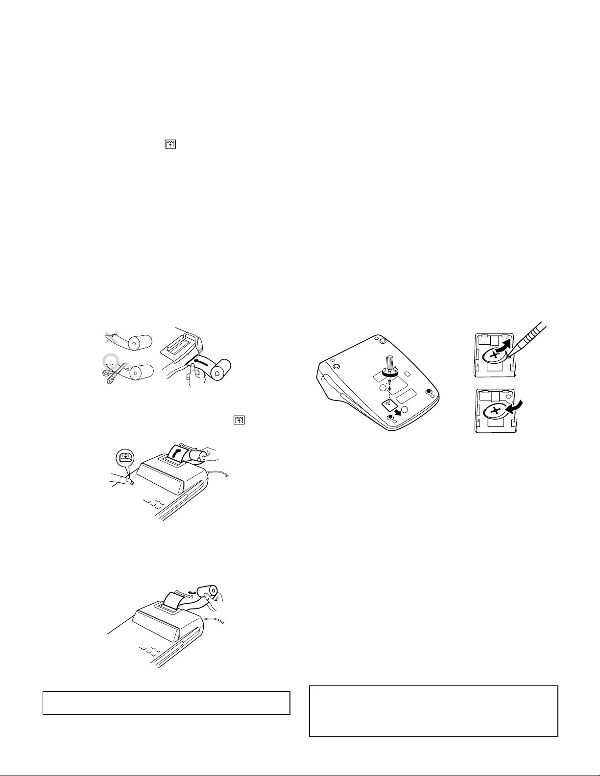
20GS6346000//// AK C Paper holder
30GS6150670//// AE C Paper cutter
40GS6118150//// AY D Upper case(ABS(PA765A))
50GS6311310//// AC C SL-SW mask(SMALL)
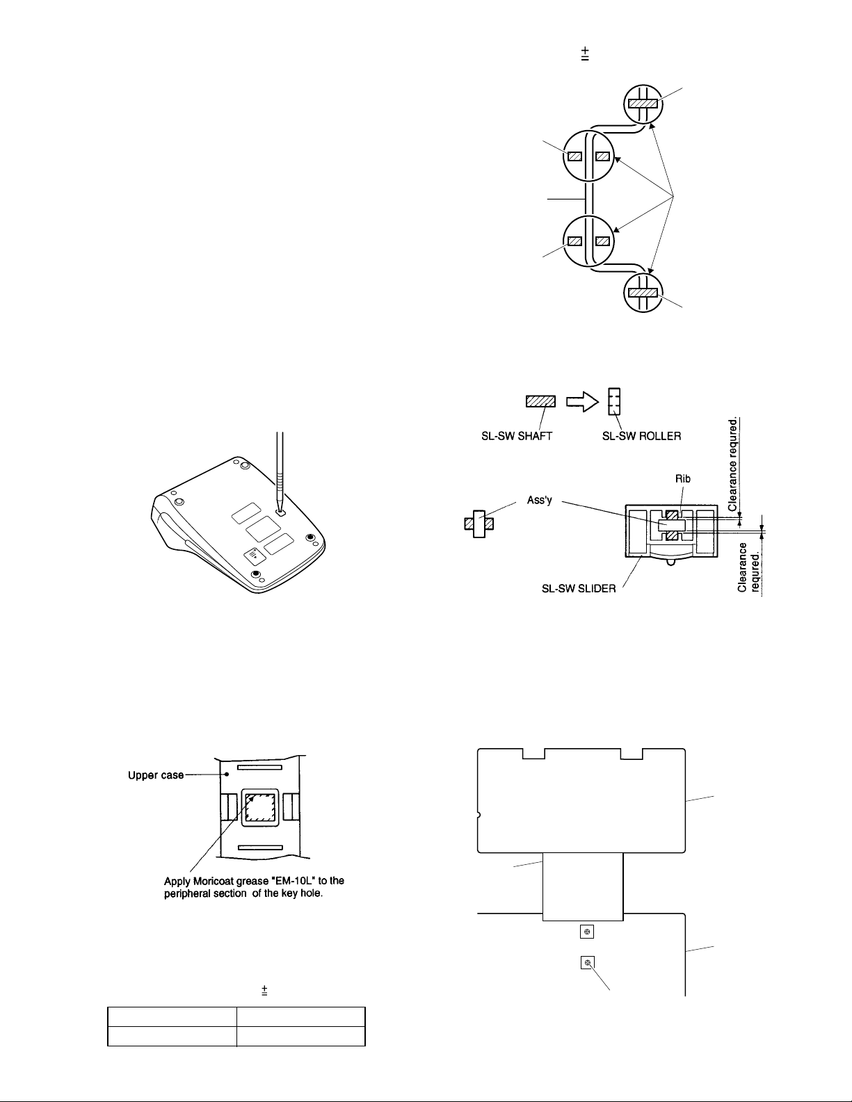
60GS6155630//// AC C SL-SW knob
70GS6311300//// AC C SL-SW mask(LARGE)
80GS6344460//// AC C SL-SW shaft
90GS6173770//// AC C SL-SW roller
!
10
0GS5420481//// AY B Power cord [AAC]
!0GS5420450//// AR B Power cord [ACO]
!0GS5420590//// AM N B Power cord(AUSTRALIA) [ABC]
!0GS5420160//// AP B Power cord(CEE TYPE) [TRC]
11 UBNDA1008CCZZ AA C Cord band
12 KI-OB1078CCZZ BC E Printer unit(MFL87)
13 0GS3110130//// AL C Ferrite core [AAC,ACO,ABC]
14 PTUBU1004CCZZ AA C Protection tube(M4) [AAC,ACO,ABC]
!
15
0GS3120620//// AV B Transformer(230V) [AAC,ACO]
!0GS3120640//// AR N B Transformer(240V) [ABC]
!0GS3120670//// AR N B Transformer(MULTI) [TRC]
16 0GS4510970//// BA B Display tube(13LT47GN)
17 XUBSD26P06000 AA C Screw(2.6×6) [for PWB,P/H]
18 0GS5111080//// AF C Flat cable(K/B+M/B)
19 0GS6346010//// AD C Key finger(for +KEY)
20 0GS6346020//// AC C Key finger(for 0KEY)
21 0GS5533910//// AM C Key rubber
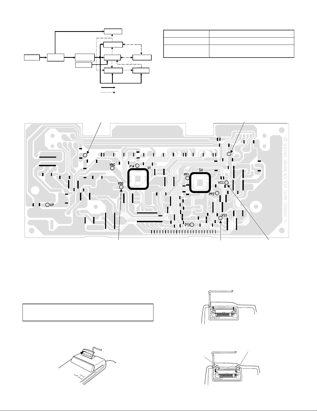
22 0GS5624810//// AS E PWB(KEY BOARD)
23
0GS6127580//// AX D Lower case(ABS(without Back-up)) [AAC,ABC]
0GS6127860//// AX D Lower case(ABS(with Back-up)) [ACO]
0GS6127876//// AX D Lower case(With hole for V/S) [TRC]
24 0GS6314680//// AC C Cushion(FOR TRANSFORMER)
25 0GS6311350//// AA C Cushion(FOR Display tube)
26 0GS5533930//// AC C Reset rubber [ACO]
27 0GS6316021//// AA C Reset sheet [ACO]
28 XUPSN30P10000 AB C Screw(3×10) [for CABINET]
29 0GS6320580//// AB D Rubber foot
30 0GS6315990//// AE C Ring spacer [ACO]
31 0GS6510870//// AB C Screw [for BATTERY COVER][ACO]
32 0GS6132460//// AE D Battery cover [ACO]
33 0GS9435250//// AA D Date code label [ACO]
34 0GS6345980//// AD C Battery contact platec[ACO]
35 0GS6345991//// AD C Battery contact plated[ACO]
36 0GS6150640M/// AM C Key unit-2(5key tops)(*M,M,M-,M+,GT)
37 0GS6150690A2// AC C Key unit-4(P/F,XRATE,÷RATE,+/-,MU)
38 0GS6150640T/// AG C Key unit-3(2key tops)(TAX+,TAX-)
39 0GS6150640S/// AE C Key unit(1key top)(-=)
40 0GS6150690B2// AC C Key unit-6(STR,#/,*,→,CE,+=,%,÷,X)
41 0GS6150640N/// AT C Key unit-1(12key tops)(0,1,2,3,4,5,6,7,8,9,00,n)
42
0GSEL1607P30AA BK E PWB unit(PWB Unit = Main PWB + all parts except the printer unit,transformer,key PWB and
cables.) [AAC]
0GSEL1607P30AC BK E PWB unit(PWB Unit = Main PWB + all parts except the printer unit,transformer,key PWB and
cables.) [ACO]
0GSEL1607P30AB BK NEPWB unit(PWB Unit = Main PWB + all parts except the printer unit,transformer,key PWB and
cables.) [ABC]
0GSEL1607P30TR BK NEPWB unit(PWB Unit = Main PWB + all parts except the printer unit,transformer,key PWB and
cables.) [TRC]
!43 QPLGA1023CCZZ AG B Plug change adaptor [TRC]
44 TCAUA1213CCZZ AA D V/S caution tag B(for AC CORD) [TRC]
45 XUPSN30P10000 AB C Screw(3×10) [TRC]
46 0GS5253340//// AN B Voltage selector(ROTARY SWITCH) [TRC]
!47 0GS3610270//// AD A Fuse(T125mA) [TRC]
48 0GS6174280//// AD C Fuse holder [TRC]
49 PTUBU1004CCZZ AA C Protection tube(M4) [TRC]
50 TCAUA1210CCZZ AB D V/S caution label B(for LOWER CASE) [TRC]
51 0GS9469290//// AB D Fuse label(T125mA) [TRC]
101 0GS6150690//// BA C Key top set

EL-1607PV
–3 –
2Packing material &Accessories
3PWB unit
NO. PARTS CODE PRICE
RANK NEW
MARK PART
RANK DESCRIPTION
1
0GS9202820//// AD D Manual(E/F/S) [AAC]
0GS9202830//// AD D Manual(E/G/F/S/I/N/SW/FI) [ACO]
0GS9202831//// AN N D Manual(E/G/F/S/I/N/SW/FI)Å{Russia) [ACO]
0GS9202990//// AD N D Manual(E/F/S) [ABC]
0GS9203000//// AD N D Manual(E/F/S) [TRC]
20GS9183920//// AC D Warning leaflet for battery [ACO]
3
0GS9303280//// AP D Gift box [AAC]
0GS9303290//// AP D Gift box [ACO]
0GS9303550//// AN N D Gift box [ABC,TRC]
40GS9411801//// AC D P.E.bag [for AC CORD]
50GS9428740//// AP D Pulp mold(L)
60GS9428750//// AP D Pulp mold(R)
70GS9413720//// AE D P.E.bag (for UNIT)[AAC,ACO]
80GS9413830//// AA D P.E.bag (for Manual)[ACO]
90GS9413820//// AA D P.E.bag (for BATTERY)[ACO]
NO. PARTS CODE PRICE
RANK NEW
MARK PART
RANK DESCRIPTION
1VCEAGU1HW227M AC C Capacitor(50WV 220µF) [C21]
20GS223383700WE AH C Capacitor(3300µF/16V) [C22]
3VCEAGU1HW106M AB C Capacitor(50WV 10µF) [C16,C19]
4VCEAGU1HW335M AA C Capacitor(50WV 3.3µF) (ACO)[C20]
5VCEAGU1HW105M AA C Capacitor(50WV 1.0µF) [C8]
6VCKYPU1HB103K AA C Capacitor(50WV 0.01µF) [C3,C7,C25]
70GS2510467//// AE C Capacitor(0.1µ/50V) [C2,C9,C15,C17,C18,C23]
8VCKYPU1HB102K AA C Capacitor(50WV 1000pF) [C11,C12,C13,C24,C26]
9VCKYPU1HB181K AA C Capacitor(50WV 180pF) [C27]
10 VCKYPU1HB101K AA C Capacitor(50WV 100PF) [C10,C14]
11 VCKYPU1HB470K AA C Resistor(47pF/50V) [C4,C5,C6]
12 VRD-HT2EY563J AA C Resistor(1/4W 56KΩ±5%) [R1,R12]
VRD-HT2EY563J AA C Resistor(1/4W 56KΩ±5%) (ACO)[R28]
13 VRD-HT2EY682J AA C Resistor(1/4W 6.8KΩ±5%) [R3]
14 VRD-HT2EY333J AA C Resistor(1/4W 33KΩ±5%) [R4]
15 VRD-HT2EY104J AA C Resistor(1/4W 100KΩ±5%) [R5]
16 VRD-HT2EY104J AA C Resistor(1/4W 100KΩ±5%) (AAC,ABC,TRC)[R30]
17 VRD-HT2EY1R0J AA C Resistor(1/4W 1Ω±5%) (AAC,ACO)[R6,R7,R14]
18 VRD-HT2EY102J AA C Resistor(1/4W 1KΩ±5%) [R8,R9,R10,R11]
19 VRD-HT2EY243J AA C Resistor(1/4W 24KΩ±5%) [R13]
20 VRD-HT2EY244J AA C Resistor(1/4W 240KΩ±5%) [R15,R16,R17]
21 VRD-HT2EY104G AA C Resistor(1/4W 100KΩ±2%) [R18]
22 VRD-HT2EY204J AA C Resistor(1/4W 200KΩ±5%) [R19,R31,R32,R33,R34,R35,R36,R37]
23 0GS102256G//// AA C Resistor(1/4W 2.2MΩ,±2%) [R20]
24 VRD-HT2EY472J AA C Resistor(1/4W 4.7KΩ±5%) [R21]
25 VRD-HT2EY103J AA C Resistor(1/4W 10KΩ±5%) (ACO)[R22,R23]
26 VRD-HT2EY362J AA C Resistor(1/4W 3.6KΩ±5%) [R24]
27 VRD-HT2EY332J AA C Resistor(1/4W 3.3KΩ±5%) [R25]
28 0GS1901610//// AC C Resistor(1W 1.8kΩ,±5%) [R26]
29 VRD-HT2HY182J AA C Resistor(1/2W 1.8KΩ±5%) [R27,R29]
30 VRD-HT2HY101J AA C Resistor(1/2W 100Ω±5%) [R38]
31 VHEHZ5C1///-1 AB B Zener diode(HZ5C1) (AAC,ABC,TRC)[ZD1]
VHEHZ6B1///-1 AB B Zener diode(HZ6B1) (ACO)[ZD1]
32 0GS4151491//// AE B Zener diode(HZ5B1) [ZD2]
33 VHEHZ7A2///-1 AC B Zener diode(HZ7A2) [ZD3]
34 VHD10E1N///-1 AB B Diode(10E1N) [D1,D2,D3,D4,D10,D13]
35
VHDDSS131//-1 AA B Diode(DSS131) [D5,D6,D7,D8,D9]
VHDDSS131//-1 AA B Diode(DSS131) [D17,D18,D20]
VHDDSS131//-1 AA B Diode(DSS131) (ACO)[D11,D12,D14]
36 0GS4140640//// AC B Diode(SD103A) [D19]
0GS4140640//// AC B Diode(SD103A) (ACO)[D15,D16]
37 VS2SA1015-Y-1 AB B Transistor(2SA1015Y) [Q1,Q2]
38 VS2SC3068-/-1 AD B Transistor(2SC3068) [Q3]
39 VS2SD2396JK-1 AE B Transistor(2SD2396) [Q4]
40 VS2SC1815-GRC AB B Transistor(2SC1815-GRC) (ACO)[Q5]
41 0GS1911030//// AD C Resistor(1/8W 10kΩ×4,±5%) [RP1]
42 0GS4151480//// AD B Zener diode(HZ18-3) (TRC)[ZD4,ZD5,ZD6]
(Unit)
901
0GSEL1607P30AA BK E PWB unit(PWB Unit = Main PWB + all parts except the printer unit,transformer,key PWB and
cables.) [AAC]
0GSEL1607P30AC BK E PWB unit(PWB Unit = Main PWB + all parts except the printer unit,transformer,key PWB and
cables.) [ACO]
0GSEL1607P30AB BK NEPWB unit(PWB Unit = Main PWB + all parts except the printer unit,transformer,key PWB and
cables.) [ABC]
0GSEL1607P30TR BK NEPWB unit(PWB Unit = Main PWB + all parts except the printer unit,transformer,key PWB and
cables.) [TRC]

q
COPYRIGHT 2004 BY SHARP CORPORATION
All rights reserved.
Printed in Japan.
No part of this publication may be reproduced,
stored in a retrieval system, or transmitted.
In any form or by any means,
electronic, mechanical, photocopying, recording, or otherwise,
without prior written permission of the publisher.
SHARP CORPORATION
Digital Document Systems Group
Products Quality Assurance Department
Yamatokoriyama, Nara 639-1186, Japan
2004 February Printed in Japan t
Other manuals for EL-1607P
4
This manual suits for next models
4
Table of contents
Other Sharp Cash Register manuals

Sharp
Sharp ER-1017 User manual

Sharp
Sharp ER-A310 Owner's manual

Sharp
Sharp ER-A320 User manual

Sharp
Sharp XE-A106 User manual

Sharp
Sharp ER-A347 User manual

Sharp
Sharp XE-A407 User manual

Sharp
Sharp XE-A407 User manual

Sharp
Sharp ER-A411 User manual

Sharp
Sharp XE-A101 User manual

Sharp
Sharp ER-A610 User manual

Sharp
Sharp ER-A460 Owner's manual

Sharp
Sharp ER-A330 User manual

Sharp
Sharp ER-A310 User manual

Sharp
Sharp XE-A406 Parts list manual

Sharp
Sharp XE-A101 User manual

Sharp
Sharp XE-A201 User manual

Sharp
Sharp ER-A520 User manual

Sharp
Sharp XE-A130 User manual

Sharp
Sharp ER-A460 User manual

Sharp
Sharp UP-800F User manual