CHAPTER 1. GENERAL
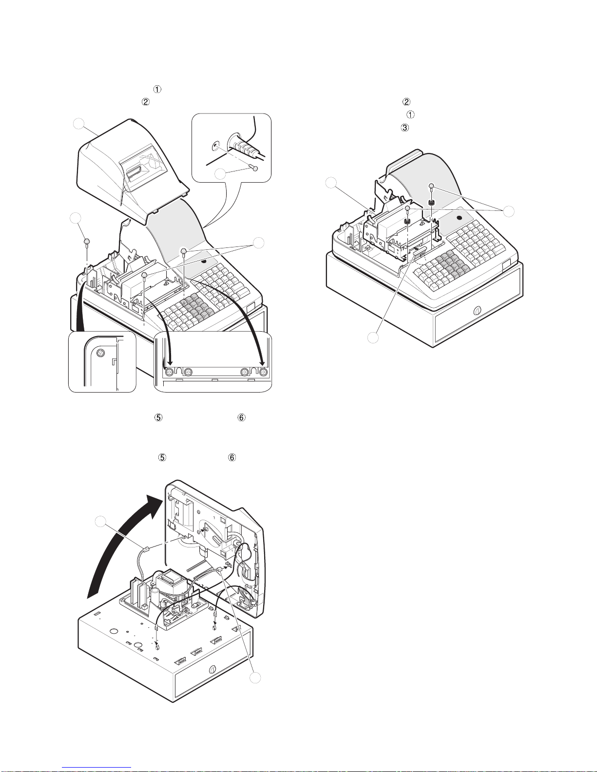
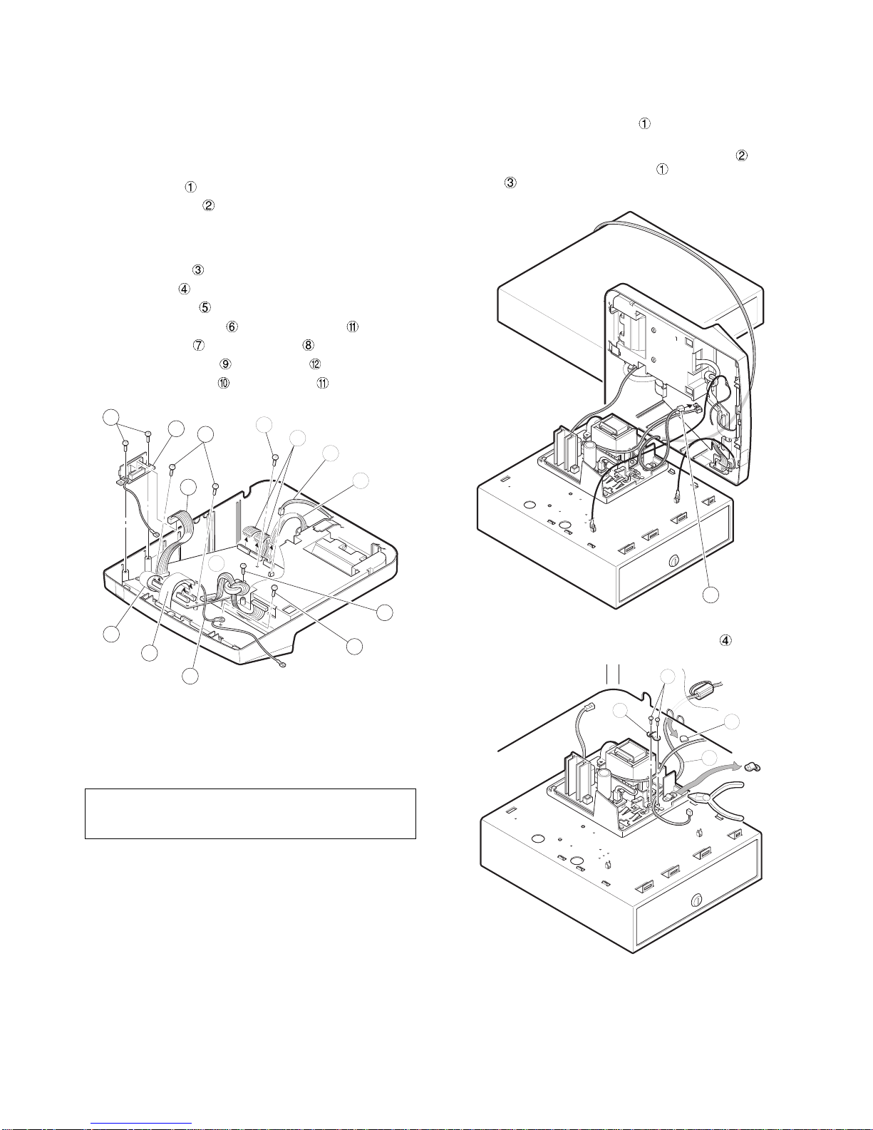
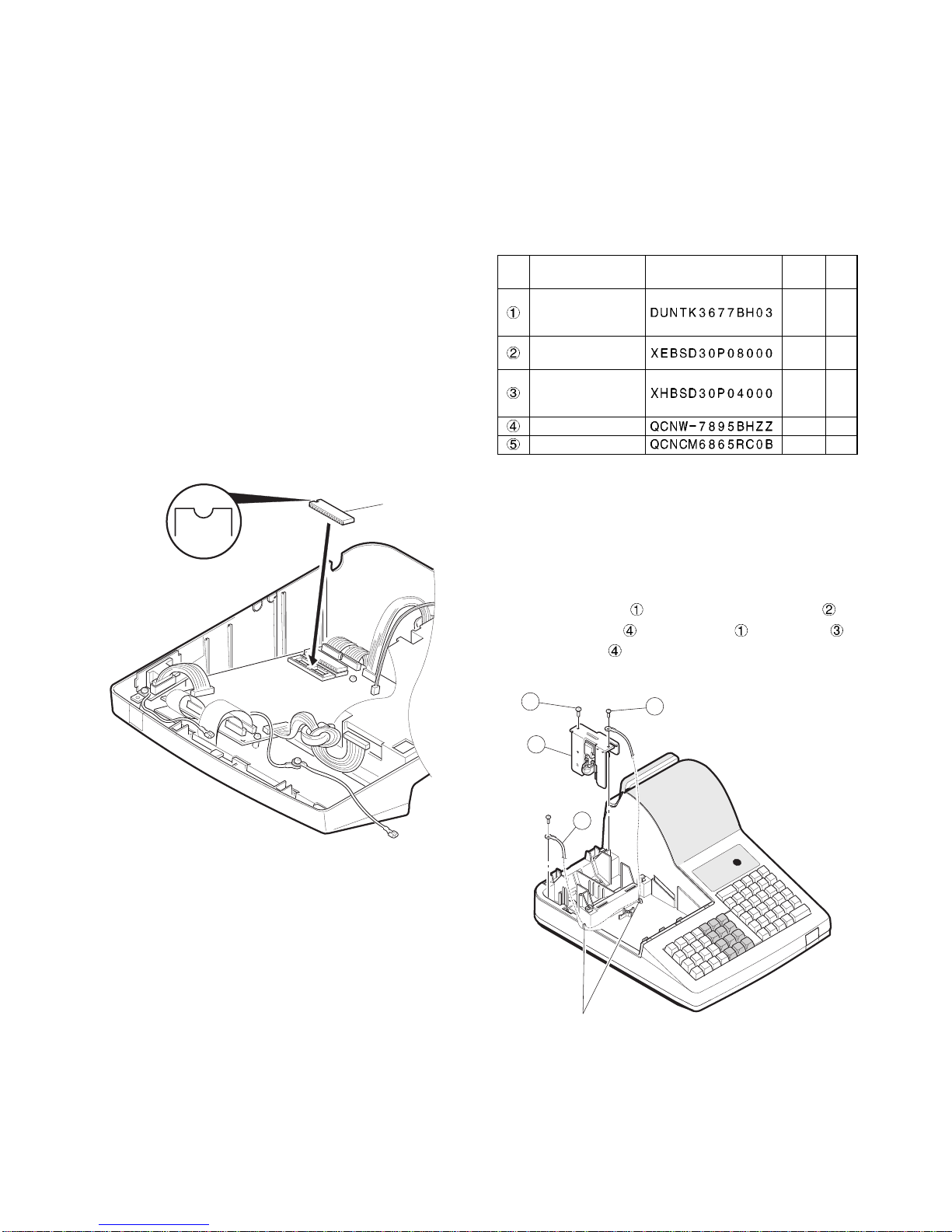
This manual describes the ER-A440 disassembly procedures and the
option attachment procedures. For assembly procedures, reverse the
disassembly procedures. For attachment of options which do not re-
quire special descriptions, descriptions are omitted.
Note for operations
•Before operation, ground the operator’s body and perform other
necessary measure against static electricity.
•During operations, disconnect the AC cord from the outlet.
•After completion of operations, connect the connectors.
•After completion of operations, be sure to perform the master re-
set.
1. SRV. reset (Program Loop Reset)
Used to return the machine back to its operational state after a lock-
up has occurred.
Procedure
•Method 1
1) Unplug the AC cord from the wall outlet.
2) Set the mode switch to (SRV′) position.
3) Plug in the AC cord to the wall outlet.
4) Turn to (SRV) position from (SRV′) position.
•Method 2
1) Set the mode switch to PGM2 position.
2) Turn off the AC switch.
3) While holding down JOURNAL FEED key and RECEIPT FEED
key, Turn on the AC switch.
Note: When disassembling and reassembling always power up us-
ing method 1 only. Method 2 will not reset the CKDC8.
Note: SRV programming job#926-B must be set to "4" to allow PGM
program loop reset.
2. Master reset (All memory clear)
There are two possible methods to perform a master reset.
•MRS-1
Used to clear all memory contents and return machine back to its
initial settings and return keyboard back to default keyboard layout.
Procedure
1) Unplug the AC cord from the wall outlet.
2) Set the MODE switch to the (SRV′) position.
3) Plug in the AC cord to the wall outlet.
4) While holding down JOURNAL FEED key, turn to (SRV) position
from (SRV′) position.
•MRS-2
Used to clear all memory and keyboard contents.
This reset returns all programming back to defaults. The keyboard
must be entered by hand.
This reset is used if an application needs different keyboard layout
other than that supplied by a normal MRS-1.
Procedure
1) Unplug the AC cord from the wall outlet.
2) Set the MODE switch to the (SRV′) position.
3) Plug in the AC cord to the wall outlet.
4) While holding down JOURNAL FEED key and RECEIPT FEED
key, turn to (SRV) position from (SRV′) position.
5) Key position assignment:
After the execution of MRS-2, only the RECEIPT FEED and
JOURNAL FEED keys can remain effective on key assignment.
Any key can be assigned on any key position on the main key-
board.
[key setup procedure]
NOTES:
1: When the 0 key is pressed, the key of the key number on
display is disabled.
2: Push the key on the position to be assigned. With this, the key
of the key number on display is assigned to that key position.
Key number Key name Key number Key name
1 Numeric key "0" 10 Numeric key "9"
2 Numeric key "1" 11 Numeric key "00"
3 Numeric key "2" 12 Numeric key "000"
4 Numeric key "3" 13 Decimal point key
5 Numeric key "4" 14 CL key
6 Numeric key "5" 15 @/FOR key
7 Numeric key "6" 16 SBTL key
8 Numeric key "7" 17 CA/AT key
9 Numeric key "8"
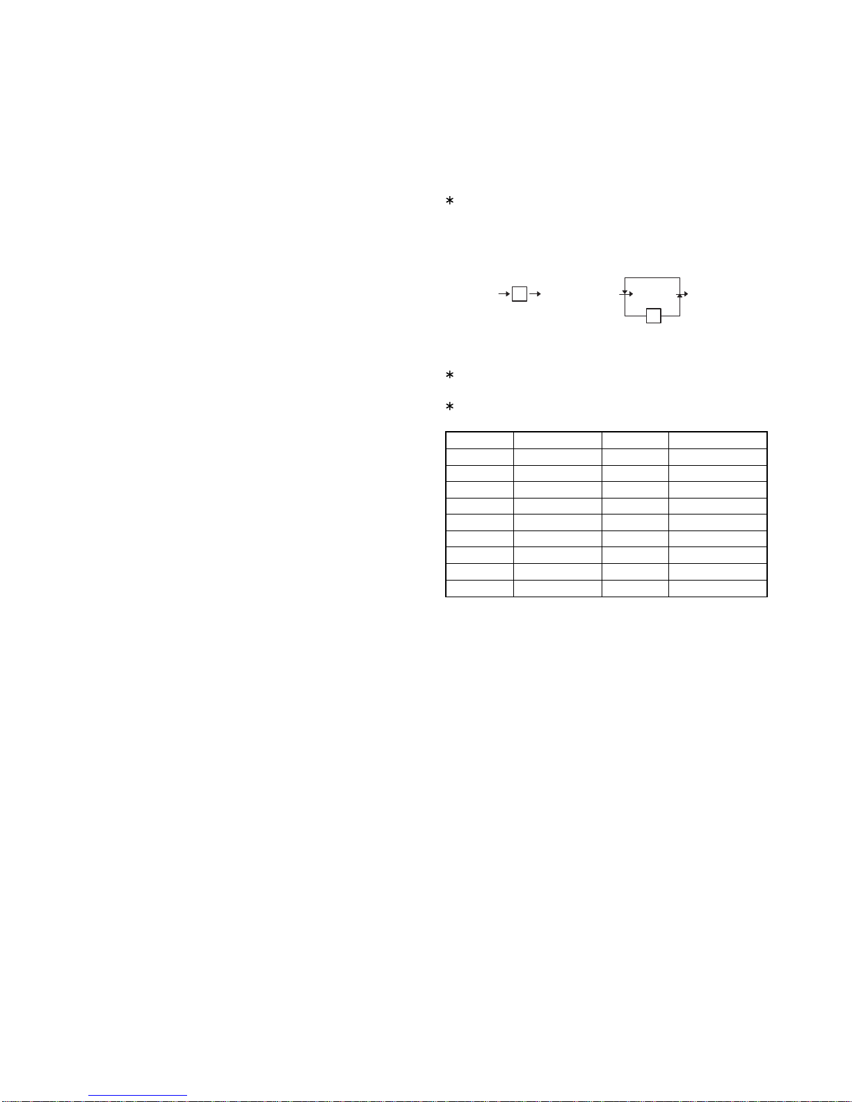
MRS-2
executed 0 Key position set Free key Free key setup
complete.
0
Disable
*1
*2
– 1 –