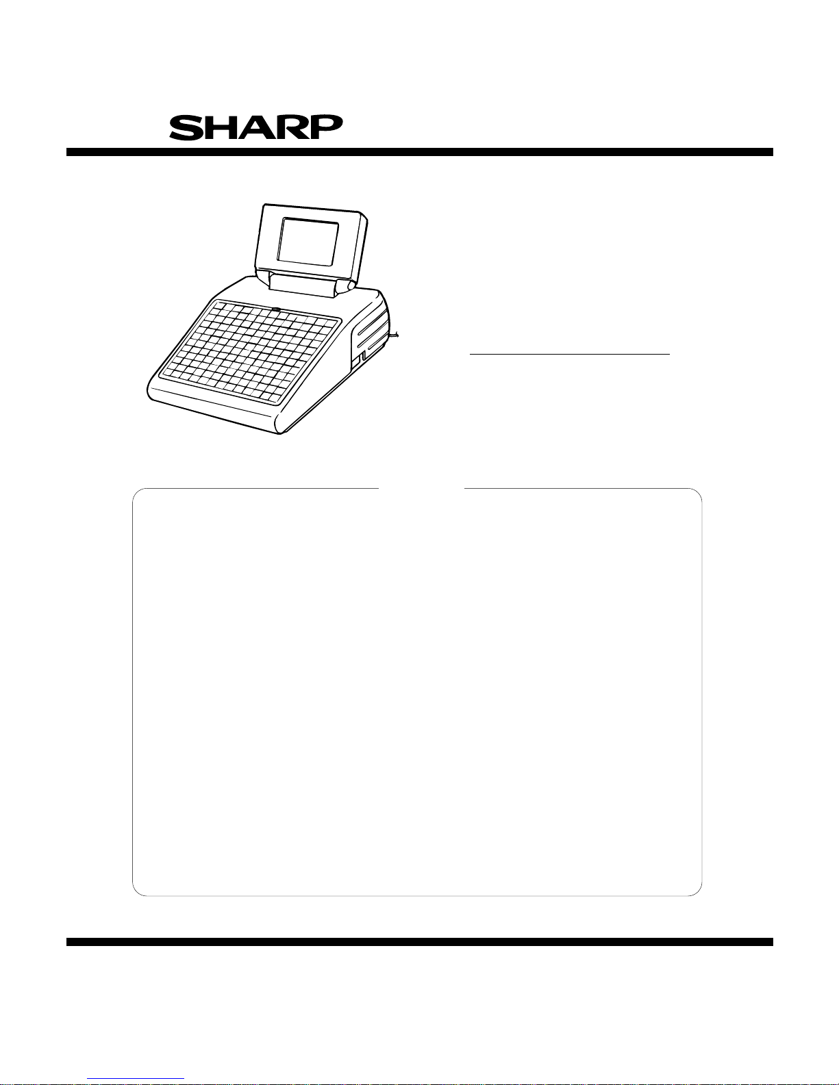
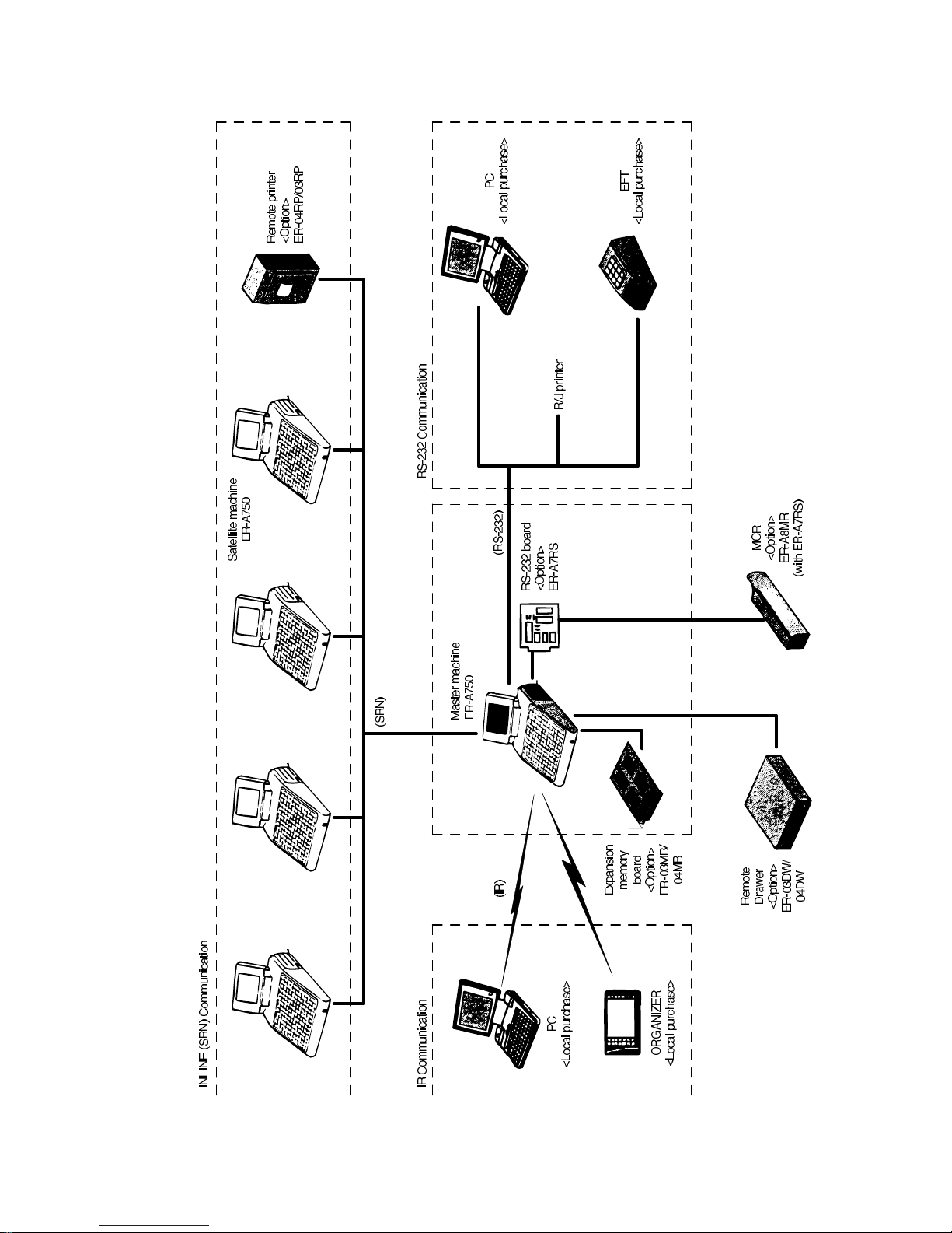
Sharp ER-A750 User manual

SERVICE MANUAL
CODE: 00ZERA750USME
MODEL ER-A750
(For"U"&"A"version)
CHAPTER 1. SPECIFICATIONS . . . . . . . . . . . . . . . . . . . . . . . . . . . . . . . . . . . . . . . . . . . . . . . . .1-1
CHAPTER 2. OPTIONS . . . . . . . . . . . . . . . . . . . . . . . . . . . . . . . . . . . . . . . . . . . . . . . . . . . . . . . .2-1
CHAPTER 3. SERVICE PRECAUTION . . . . . . . . . . . . . . . . . . . . . . . . . . . . . . . . . . . . . . . . . . .3-1
CHAPTER 4. SRV RESET (Program Loop Reset) and switch to SRVmode . . . . . . . . . . . . . .4-1
CHAPTER 5. MASTER RESET . . . . . . . . . . . . . . . . . . . . . . . . . . . . . . . . . . . . . . . . . . . . . . . . . .5-1
CHAPTER 6. DIAGNOSTICS . . . . . . . . . . . . . . . . . . . . . . . . . . . . . . . . . . . . . . . . . . . . . . . . . .6-1
CHAPTER 7. CIRCUITDESCRIPTION . . . . . . . . . . . . . . . . . . . . . . . . . . . . . . . . . . . . . . . . . . . .7-1
CHAPTER 8. PWB LAYOUT . . . . . . . . . . . . . . . . . . . . . . . . . . . . . . . . . . . . . . . . . . . . . . . . . . . .8-1
CHAPTER 9. CIRCUITDIAGRAMS . . . . . . . . . . . . . . . . . . . . . . . . . . . . . . . . . . . . . . . . . . . . . . .9-1
PARTS GUIDE
CONTENTS
SHARP CORPORATION This document has been published to be
used for after sales service only. The con-
tents are subject to change without notice.
Parts marked with "!" is important for maintaining the safety of the set. Be sure to replace these parts with specified ones for
maintaining the safety and performance of the set.

TheRBRCTM Seal
TheRBRCTM Seal on the easily removable nickel-cadmium battery pack contained
in our product indicates that SHARP is voluntarily participating in an industry program to
collect and recycle these battery packs at the end of their useful life, when taken out of
service within the United States. The RBRCTM program provides a convenient alternative to
placing spent nickel-cadmium battery packs into the trash or municipal waste stream,
which is illegal in some areas.
SHARP’spaymentstoRBRCTM makes it easy for you to drop off the spent battery pack at local retailers of
replacement nickel-cadmium batteries, or at authorized SHARP product service centers. You may also contact
your local recycling center for information on where to return the spent battery pack. SHARP’s involvement in this
program is part of its commitment to protecting our environment and conserving natural resources.
(RBRCTM is a trademark of the Rechargeable Battery Recycling Corporation.)


CHAPTER 1. SPECIFICATION
1. Apearance
Externalview
Frontview
Rear view
2. Rating
External dimensions 11.4 ×14.4 ×10.3 in. (290 ×365 ×262
mm)
Weight 11.2 lbs. (5.1 kg)
Power source 120VAC ±10% 60 Hz
Power consumption Stand-by: 22W
Operating: 25W (max.)
Working temperatures 32 to 104˚F (0 to 40˚C)
3. Keyboard
1) Standardkeyboardlayout
2) Key top name
1 Standard key top
KEYTOP DESCRIPTION
0 ∼9,00 Numeric keys
• Decimal point key
CL Clear key
@/FOR Multiplication / Split-pricing key
RCPT Receipt print key
RPSEND Remote printer send key
d 1 Discount 1 key
%1 Percent 1 key
TAX1SHIFT
TAX2SHIFT Tax 1 and 2 shift keys
RFND Refund key
VOID Void key
PASTVOID Past void key
SBTLVOID Subtotal void key
RTN Return key
PLU/SUB Price lookup / Subdepartment key
1 ∼99 Direct price look up key
LEVEL 1 ∼5 PLUlevel shift 1 ∼5 keys
SRVC Servicekey
FINAL Final key
BAL Balance key
DRVNC New check 2 key (For drive-through)
DRVGLU Gest look up 2 key (For drive-through)
SERV# Server code entry key
EMP# Employee code entry key
MISCFUNC Miscellaneous function key
MODE Mode key
ENTER Enter key
AUTO1,2 Automatic sequencing 1 and 2 keys
CH# Charge menu key
CHK# Check menu key
TRAYSBTL Tray subtotal key
MDSESBTL Merchandise subtotal key
Operator display
Keyboard
AC cord
Power switch in
sure that the power
switch is placed in the
OFF position prior to
connecting AC power
Left side of
the machine
IR receiver cover Brightness
control
Contrast control
Power switch
Customer
Display
Rear cover
91
82
73
64
55
46
38
30
22
14
7
1
92
83
74
65
56
47
31
23
39
15
8
2
93
84
75
66
57
48
40
32
24
16
9
3
94
85
76
67
58
49
41
33
25
17
10
4
95
86
77
68
59
50
42
34
26
18
11
5
96
87
78
69
60
51
43
35
27
19
12
6
97
88
79
70
61
52
44
36
28
20
13
89
80
71
62
53
45
90
81
72
63
54
37
29
21
ENTER
CANCEL
PAGE
VOID
PAGE
UP
DOWN
LEVEL
2
LEVEL
1
LEVEL
3
LEVEL
4
LEVEL
5
MISC
FUNC
TEX1
SHIFT
RP
SEND
RCPT
1
NDSE
PAST
SERV
#
SBTL
VOID
7
4
1
0
8
5
2
00
9
6
3
TEX2
SHIFT
AUTO
1
MODE
EMP
#
BAL
1%
CHK
#
SBTL
@/
VOID
FOR
AUTO
2
RFND
RTN
CH
#
PLU/
SUB
CL
DRV
NC
DRV
GLU
SRVC
FINAL
TRAY
SBTL
$5
$10
$20
SBTL
CA/AT
1–1

KEYTOP DESCRIPTION
SBTL Subtotal key
CA/AT Cash / Amount tendered key
$5,$10,$20 Speed tender key
(Used for AUTO8,9,and 10 key)
PAGEUP Page up key
PAGEDOWN Page down key
→Cursor right key
←Cursor left key
↑Cursor up key
↓Cursor down key
CANCEL Cancel key
2 Optional key top
KEYTOP DESCRIPTION
000 000 key
98 ∼135 Direct price look up keys
1 ∼50 Department keys
%2 ∼%9 Percent 2 ∼9 keys
d 2∼d 9 keys Discount 2 ∼9 keys
CH1 ∼CH8 Charge 1 ∼8 keys
CA2 Cash 2 key
CONV1 ∼CONV4 Conversion 1 ∼4 keys
RA1,RA2 Received on account 1 and 2 keys
PO1,PO2 Paid out 1 and 2 keys
AUTO3 ∼AUTO7 Automatic sequencing 3 ∼7 keys
CHK1 ∼CHK4 Check 1 ∼4 keys
BT Bill totalize / Bill transfer key (CHECK-
ADD)
TRANSOUT Transfer out key
TRANSIN Transfer in key
CASHTIP Cash tip key
CHARGETIP Charge tip key
TIPPAID Tip paid key
EAT IN 1 ∼EAT IN 3 Eat in 1 ∼3 keys
TAX3SHIFT
TAX4SHIFT Tax 3 and 4 shift keys
DEPOSIT Deposit key
DEPOSITRF Deposit refund key
TAX Manual tax key
GRTEX Gratuity exempt key
COVERCNT Cover count entry key
BILL Bill print key
CONV# Currency conversion menu key
SHIFT1 ∼SHIFT5 Pricelevel shift 1 ∼5 keys
BACKSPACE Backspace key
DELETE Delete key
NC New check key
GLU Guest look up key
# Non-add code entry key
NS No-sale key
MGR# Manager code entry key
OPENTARE Tare entry Key
REPEAT Repeat entry key
PERSON# Person number entry key
IND.PAYMENT Individual payment key
EMPL.SALES Employee sales key
RCPSW Receipt ON / OFF key
KEYTOP DESCRIPTION
SCALE Scale entry key
3) Textprogrammingkeysheetlayout
4) Blank key sheet layout
(ENTER)
PAGE
(DC)
PAGE
UP
DOWN
1
7
4
1
0
8
5
2
00
9
6
3
(MODE)
=
1%
@/
FOR
CL
(INS)
BACK
SBTL
CA/AT
!
Q
A
@
W
S
#
E
D
$
R
F
%
T
G
^
Y
H
&
U
J
*
I
K
(
O
L
Z
X
CVBNM
,
P
/
.
(
((
(
(CANCEL)
(
(
(RECALL)
N
_
-
}{
+
][
?
,,,
><
(DEL)
SPACE
NEXT
PECORD
(
(SHIFT)
(SPACE) (SPACE) (SPACE) (SPACE) (SPACE)
~
1–2

3. Display
1) Operatordisplay
•Screen example 1 (REG mode)
•Screen example 2 (PGM mode)
Mode name
Merchandise subtotal excluding taxes
Tax amounts
Sales amount including taxes
Time
Sentinel mark (X):
Appears in the lower comer of the
screen when the cash in drawer exceeds a
programmed sentinel amount. The sentinel
check is performed for the total cash in
drawer.
Menu level shift indicator (L1):
Shows the menu level currently selected.
Price level shift indicator (P1):
Shows the PLU price level currently selected.
Numeric entry:Entered figures appear at the cursor position.
Received media type
Window
In the REG mode, it shows sales information you have just entered such as items, tax amounts
and media types.
Server name
Receipt ON/OFF status:
Stock alarm lamp
Receipt OFF:R
Receipt ON:Blank
Time
Mode name
Casp lock indicator(A/a):
The upeer-case letter "A" appears when
Caps Lock is on, and the lower-case
letter "a" appears when Caps Lock is off
during text programming.
Double-size character mode indicator(W):
Apperars when the double-size character
mode is selected during text programming.
Window
In the PGM mode,
programmable items are listed.
Items remain bottom of the window
1–3

Device type LCD display
Dot format 320(W)×240(H) Full dot
Dot size 0.33 ×0.33 mm
Dot space 0.03 mm
Dot color White
Back color Dark blue
Weight 180 g
2) Customerdisplay
ST: Lights up when a subtotal is displayed.
CG: Lights up when the change due amount appears in the dis-
play or when the total sale amount is negative.
TL: Lights up when you finalize a transaction by pressing the
CA/AT , CA2 , CHK
1throuth
CHK
4or
CH
1through
CH
8
without any amount tendered entry.
VOID: Lights up when the VOID key or PAST
VOID key is pressed or
when an item void entry is made.
RFND: Lights up when the RFND key is pressed or when a refund
item entry is made.
Device type 7 segment display tube
Number of lines 1 line
Number of positions 7 positions numeric display
Color of display Green
Character size 13(H) ×6(W) mm
3) Displayadjustment
You can adjust the brightness and contrast of the display by using
the corresponding controls.
ST CG
TL
VOID
RFND
Machine state
indicator lamps
Amount
Contrast control
Turning the control backwards
darkens the display and turning
it forwards lightens the display.
Brightness control
Turning the control backwards
darkensthe display and turning it
forwards brightens the display.
1–4

CHAPTER2. OPTIONS
1. System configuration
2–1

2. Options
No. NAME MODEL DESCRIPTION
1 ON-LINESYSTEM ER-A7RS 2 port RS232 I/F
MCRI/F
2 EXPANSION
MEMORYBOARD ER-03MB 1MBPS-RAM
ER-04MB 2MBPS-RAM
3 REMOTEPRINTER ER-03RP
ER-04RP
4 MCR
(Magnet Card Reader) ER-A8MR
5 DATABACKUP
SYSTEM ER-02FD FD unit
CE-IR2 WirelessI/Ffor IR
comunication
CE-IR4
3. Service tools
No. NAME PARTSCODE PRICE
RANK DESCRIPTION
1 TERMINATOR(50Ω) QCNCM7145RCZZ AZ For SRN in-line system
2 EXPANSIONPWB CKOG-6724BHZZ BX
3 MCR test card UKOG-6718RCZZ BE ForER-A8MR
4 RS232LOOPBACKCONNECTOR UKOG-6705RCZZ BC For RS232 connector
4. Supplies
No. NAME PARTSCODE PRICE
RANK DESCRIPTION
1 STANDARDKEYSHEET PSHEK6849BHZZ AS
2 PROGRAMMINGKEYSHEET PSHEK6850BHZZ AH
3 BLANKKEYSHEET PSHEK6818BHZZ AQ
2–2

5. How to use service tools
5-1. ExpansionPWB:CKOG-6724BHZZ
•Extrenal view
•Plain view
•Connection diagram
5-2. MCR test card: UKOG-6718RCZZ
•Used when executing the diagnostics of the ER-A8MR.
•External view
Test pins : Used to check the bus signals.
Bus connector : Used to check the bus signals.
Connected to the ER-A750 Mother PWB.
ER-A750 bus connector
ER-A7RS
2–3

CHAPTER 3. SERVICE PRECAUTION
1. Adjustment for SRN (IN-LINE) interface
circuit
If transistor Q10 in the transmitter/receiver section has been re-
placed or if the SRN level requires readjustment, the following align-
ment is required:
1) Tools and Instruments Required
1 Oscilloscope (50MHz or better) . . . . . . . . . . . . . . . . . . . . . . . . . . . 1
2 ER-A750 . . . . . . . . . . . . . . . . . . . . . . . . . . . . . . . . . . . . . . . . . . . . 1
2)DummyNetworkSpecifications
Fig. 1 Dummy network
The oscillator should be connected to the points indicated by ⊕and
$.
⊕: Connect the positive side of the oscillator.
$: Connect the negative side of the oscillator.
3) Connections
Fig. 2
Attach the BNC connector to the SRN connector (CON 15) on the
main PWB.
4)AlignmentProcedure
1When Using an Oscillator
a) Checking the 1MHz oscillator output
Using an oscilloscope check the 1MHz oscillator’s output waveform.
Fig. 3 1MHz oscillator output waveform
NOTE: The oscillator used should have an output impedance of
50Ω.
b) Connecting the oscillator and its adjustment
Connect a dummy network or branch-trunk network to the output of
the SRN connector (CON 15), and connect the oscillator to the
dummy or branch-trunk network.
* Waveform adjustment
Adjust VR4 until the signal waveform as shown in Fig. 5 is obtained
across IC34 (pin 1 of the 75115) and GND pin.
Turning VR4 clockwise extends the interval of T1.
Fig. 5 Receiver regeneration waveform (with dummy network)
Fig. 6 Board location
2When the Branch Trunk Network and Two POS’S are Available.
a) Connecting terminals
Both ends of the network must be terminated with a 50Ωterminator.
If only two active terminals are tested and left on the network, dis-
connect all other terminals from the network. (In this case as well,
both ends of the trunk network must be terminated with 50Ω).
Fig. 7 Terminal connection
R1 100
Ω
J (1/4W carbon)
R2 150
Ω
J (1/4W carbon)
C1 0.01µ F (mylar firm)
C1
R1
R2
BNC connector
Main PWB
5V
0V
0.5µ S 0.5µ S
VOH
VOL
T1 = 580 to 620ms
T2 = 380 to 420ms
T1 T2
Main PWB
VR4
IC34 Q10
Pin No.1
R4 CON15
A
ER-A750
R50
Ω
R50
Ω
ER-A750
3–1

b) Receive level adjustment
i) Turn on both the receiver terminal and the transmitter terminal.
ii) Run the diagnostic program "Flag send check" on the transmitter
terminal to send a flag.
iii) Checking transmitter terminals’ output waveform
Using an oscilloscope, check the transmitter terminal’s output
signal waveform.
Fig. 8 Transmitter terminal’s output waveform
(at transmitter output)
At the receiver terminal, the transmitter terminal’s output wave-
form is subject to attenuation and distortion due to the length of
the trunk cable (this depends on the characteristics of the cable
itself).
Fig. 9 Example of distorted signal waveform at the receiver terminal
(RG58/U400m)
Adjust the receiver terminal adjust VR4 (20kΩ) on the main PWB
until the waveform as shown in Fig. 10 is obtained at IC34 (pin 1
of the 75115). (For the location of VR4, see Fig. 6 Board location
of this subsection).
Clockwise rotation of VR4 extends the High level pulse width of
the signal at IC34 (pin 1 of the 75115).
Fig. 10 Waveform at IC34 (pin 1 of the 75115 IC in the receiver
terminal)
5) Other Checks (These Checks should be done
AftertheReceiveLevelAdjustmentis
Completed).
1Line driver bias control circuit
Make sure that the voltage at the A-side lead of the R4 resistor
(150Ω, 3W) shown in Fig. 6 is properly switched.
Procedure:
i) Connect a terminating resistor or read network to the BNC con-
nector,QCNW-6856RCZZ(Fig.2).
ii) Run the diagnostic program "Data send check", and make sure
that the voltage at point A (in Fig. 6) is switched as shown in Fig.
11.
Fig. 11 bias circuit switching waveform
iii) If the waveform as shown in Fig. 11 is not obtained, it is most
probable that transistor Q10 (2SC4699) is defective.
2For the other check items, refer to DIAGNOSTICS
SPECIFICATIONS
2. Battery label
The battery label is attached to the main chassis on the back surface
of the set.
The battery label has the column to show the battery replacement
date. Put down the date in the following cases:
(The battery life is about 3 years after replacement.)
•When the set is installed.
•When the battery is replaced after installation.
CAUTION:
When the time written below comes, ask your dealer for a
replacement of the battery.
VORSICHT:
Wenn die untenbenannte Zeit erreicht wird, ersuchen Sie bitte
Ihren Fachhändler um den Austausch der Batterie.
PRECAUTION:
Lorsque le temps écrit ci-après arrive, demander à votre
revendeur local de remplacer la batterie par une nouvelle.
ADVERTENCIA:
Cuando se alcance el tiempo indicado abajo, solicite a su
distribuidor que reemplace la batería.
Time to replace :
Austauschzeit :
Le temps de la remplacer :
Tiempo de reemplazo :
______________________
______________________
______________________
3. Precautions in installing optional RAM
PWBs
1) Background
The ER-A750 can use the ER-03MB or the ER-04MB as an optional
RAM PWB. The ER-03MB and the ER-04MB are available in two
versions according to the difference in access time of the pseudo-
SRAM.
(1) 150 ns access time version (Not marked with "| "; manufactured
before June, 1996; shipped only to North America and Europe)
(2) 120 ns access time version (Marked with "| "); manufactured
after July, 1996 These two versions can be identified, one from
the other, by whether or not the "| " mark is stamped on the
white background as shown in Fig. 1 and by the marking on the
case. (See Fig. 1.)
1µ S 1µ S
3.8V
0.8V
1µ S 1µ S
12V
0V
4.3ms
17ms
3–2

PWB marking
Packing case
2) Cautions to be exercised when using the RAM
PWBswiththeER-A750
When using the above-mentioned RAM PWB version (1) with the
ER-A750, it is necessary to correct the RAM access timing. Use of
the above-mentioned RAM PWB version (2) does not require the
correction of the RAM access timing. For this purpose, a hardware
jumper (JP1), designed to judge to determine whether or not to
correct the RAM access timing, is located on the main PWB of the
ER-A750 (Fig. 2). Before installing an optional RAM PWB, check its
version by referring to the description given in the above-mentioned
(1) and (2) and set the jumper as shown below. (The ER-A750 has
been factory-set for 150ns access time and TP cycle inserted.)
Fig. 3 Setting of the JP1 on the main PWB of the ER-A750
(1) Setting when the ER-03MB or the ER-04MB is not marked with
"| "
(Position to which the ER-A750 has been factory-set)
(2) Setting when the ER-03MB or the ER-04MB is marked with "| "
(ER-03MB/04MB PWB Face side)
Imprint " " on this white area.
C
E
Imprint " " on the right side of the
model rabel.
Indivi dual case
E
C
Imprint " " under the model label.
Colleclive case
E
C
B
3 2 1
MAIN PWB
+C17
Q6
IC27
1
3
JP1
ZD4
1
IC16
Short position
IN case of (1)
IN case of (2)
13
13
3–3

3) Difference in operation according to the setting
of the jumper
Only when the ER-03MB or the ER-04MB is used in the above setting
state (1) will one cycle (i.e., cycle for generating pre-charge time of
the quasi-SRAM: TP cycle) of access be additionally inserted into the
CPU, thereby delaying the CPU speed slightly.
4) Factory-settingoftheER-A750
The ER-A750 has been factory-set so that the JP1 is in the setting
state (1) (TP cycle inserted). However, if it has neither the ER-03MB
or the ER-04MB installed to it, this is automatically detected by soft-
ware, so the additional insertion of the TP cycle is not performed.
Note:
When installing the ER-03MB or the ER-04MB, check the position
of the jumper by referring to Fig. 3.
Improper setting of the jumper may result in malfunction.
4. IR module (PRM-850) soldering
conditions
When replacing the IR module (IC1), observe the following condi-
tions.
Solder the IR module with the solder tip temperature at 280 degrees
C within 3 sec.
5. IPL (Initial Program Loading) function
1) Introduction
The application software of the ER-A750 is written in the flash ROM
(IC6: VHILH80S01-1). In the following cases, writing procedure of
the application software into the flash ROM is required:
•When the flash ROM (IC6: VHILH80S01-1) is replaced with new
one. The service part flash ROM does not include the application
software in it.
•When IPL writing is required because of change in the application
software.
* The service part of the main PWB unit (CPWBX7510BH01) in-
cludes the flash ROM (IC6: VHILH80S01-1) with the application
software written in it, and there is no need for writing the applica-
tion software when replacing the main PWB unit.
2) IPLprocedure
There are two ways of IPL procedures.
•IPLfromP-ROMviaER-A7RS
•IPL from PC via IR (infrared) communication
The detailed descriptions on the above procedures are given below.
3) IPL from P-ROM via ER-A7RS
(1) Install the master ROM to the IC socket (IC12) on the ER-A7RS.
MasterROM:Partcode:VHI27801RAA1A
(2) IPL switch on the ER-A7RS: Set the IPL SW to ON position.
(3) InstalltheER-A7RStothe ER-A750.(The ER-A750power should
be turned OFF.)
(4) Turn on the power of the ER-A750.
(5) The following display is shown and the IPL procedure is started.
When the procedure is completed, the message of "Com-
pleted." is shown. LCDDISPLAY
IPL from PROM
C0 C1 C2 C3 C4 C5 C6 C7
C8 C9 CA CB CC CD CE CF
Completed.
Main PWB
Location No.IC1
Part code: VHIRPM850CB-1
P-ROM
IC12
IPL SW
OFF
ON
ER-A7RS
ER-A750
(SIDE VIEW)
3–4

(6) Turn off the power of the ER-A750.
(7) Removethe ER-A7RSfrom theER-A750.
(8) Perform the master reset. (Refer to CHAPTER 4.)
4) IPL from PC via IR (infrared) communication
(1) IR communication between the ER-A750 and PC is as follows:
(2) Procedures on the PC side and on the ER-A750 side are as
follows:
RS-232C
CE-IR4
PC
without IR
ER-A750
ER-A750
PC with IR
1. PC+CE-IR4 system
2. PC only system
No Procedure on P.C. side No ProcedureonER-A750 side
1 Copy “A7IPL.EXE” and S-type ROM object file
(ex. “A750_0A.ROM) into your Personal Computer (P.C.).
* “A7IPL.EXE” and S-type ROM object file is separately
supplied. 2 Turn OFF the power.
3 Select IPL Receiving Mode.
Set IPL switch “ON”.
1 Open the IR cover of the ER-A750.
2 IPL switch: Set the IPLIR SW to the left side when
viewed from the front.
4 Turn ON the power.
5 Starting of IPL Receiving Mode.
ER-A750shows
“IPL from IR”
IPL from IR
6 ConnectP.C.and ER-A750viaIR.
ER-A750
(SIDE VIEW)
IR unit
IPLIR SW
IPLIR SW
3–5

7 Execute“A7IPL.EXE”on P.C.
Operation:
> A7IPL A750_0A.ROM
(“A750_0A.ROM” is file name of S-type ROM object.)
8 Program data is sent to ER-A750 automatically. 8 Program data is received from P.C. automatically.
IPL from IR
ConnectedIRDA115200
C1 C2 C3 C4 C5 C6 C7 C8
C9 CA CB CC CD CE CF
9 “A7IPL.EXE” is completed. 9
P.C.shows ER-A750shows
“Completed.” “Completed.”
IPL from IR
ConnectedIRDA115200
C1 C2 C3 C4 C5 C6 C7 C8
C9 CA CB CC CD CE CF
Completed.
10 Turn OFF the power.
11 Select Normal Mode.
Set IPL switch “OFF”.
12 Execute “Master reset” on ER-A750.
End
3–6

CHAPTER 4. SRV RESET (Program
Loop Reset) and
switch to SRV mode
In the ER-A750, the following reset switch (location No.: S2) is used
to switch to the service (SRV) mode and to reset.
SRV. reset
Used to return the machine back to its operation state after a lock up
has occurred.
PROCEDURE
1) Turn off the AC switch.
2) Set the reset switch to “OFF” position
3) Turn on the AC switch.
4) Turn to “ON” the reset switch.
5) The SRV mode is displayed as shown below.
DISPLAY:
Reset
switch
1Side(Rear side):"ON" position(Reset state)
3Side(Front side):"OFF" position(Reset cancel)
4–1

CHAPTER 5. MASTER RESET
(All Memory Clear)
There are two possible methods to perform a master reset.
MRS-1 (Master resetting 1)
Used to clear all memory contents and return machine back to its
initial settings.
Return keyboard back to default for default kyeboard layout.
PROCEDURE
1) Turn off the AC switch.
2) Set the reset switch to “OFF” position
3) Turn on the AC switch.
4) While holding down MRS-1 key , turn to “ON” the reset switch.
* MRS-1key: The key located on Left upper corner of the key-
board.
Keyboard layout
5) Enter the password key operation
DISPLAY:
ENTERPASSWORD
Password input procedure: Press the four corners of the key-
board in the sequence of a, b, c, and
d.
Keyboard layout
6) Master reset is started.
DISPLAY:
MASTER RESET
7) After completion of the master reset, the buzzer sounds three
times and the following SRV mode display is shown.
DISPLAY:
MRS-1 Key
a
c
db
5–1

MRS-2 (Master resetting 2)
Used to clear all memory and keyboard contents. This reset returns
all programming back to defaults.
The keyboard must be entered by hand. This reset is used if an
application needs different keyboard layout other than that supplied
by a normal MRS-1.
PROCEDURE
1) Turn off the AC switch.
2) Set the reset switch to “OFF” position
3) Turn on the AC switch.
4) While holding down MRS-2 key , turn to “ON” the reset switch.
* MRS-2key: The key located on Right upper corner of the
keyboard.
Keyboard layout
5) Enter the password key operation
DISPLAY:
ENTERPASSWORD
Password input procedure: Press the four corners of the key-
board in the sequence of a, b, c, and
d.
Keyboard layout
6) Set the fixed keys in the table below. (Start from the zero “0” key,
The keys are displayed sequentially.)
DISPLAY:
ENTER 0 KEY
[Key setup procedure]
MRS-2
executed 0Key
position set Freekey Setup
complete
0
Disable
NOTES:
*1: When the 0 key is pressed, the key of the key number on
display is disabled.
*2: Push the key on the position to be assigned. With this, the
key of the key number on display is assigned to that key
position.
*3: When relocating the keyboard, the PGM 1/2 mode use stan-
dard key layout.
Key
No. Key name Key
No. Key name Key
No. Key name
001 “0” key 011 “00” key 022 “CANCEL” key
002 “1” key 013 Decimal point “•”
key 023 “ENTER” key
003 “2” key 014 “CL” key 024 “CA/AT” key
004 “3” key 015 “@/FOR” key
005 “4” key 016 “SBTL” key
006 “5” key 017 “MODE” key
007 “6” key 018 UP “↑” key
008 “7” key 019 DOWN “↓” key
009 “8” key 020 LEFT “←” key
010 “9” key 021 RIGHT“→” key
7) Master reset is started.
DISPLAY:
MASTER RESET
8) After completion of the master reset, the buzzer sounds three
times and the following SRV mode display is shown.
DISPLAY:
MRS-2 Key
a
c
db
5–2

CHAPTER 6. DIAGNOSTICS
SPECIFICATIONS
CONTENTS
1. General..........................................................................................1
2. System configuration .....................................................................1
2-1. Test system.........................................................................1
3. Diagnostics ....................................................................................1
1) Master reset procedure..................................................1
2) Program reset (service reset) procedure.......................1
3-1. Execution of diagnostics .....................................................1
3-2. RAM Diagnostics.................................................................2
1) Standard RAM Check ...................................................2
2) VRAM Check ................................................................2
3) ER-03MB Check ...........................................................3
4) ER-04MB Check............................................................3
3-3. ROM & SSP Diagnostics.....................................................4
1) Standard ROM Check....................................................4
2) SERVICE ROM Check ..................................................4
3) SSP Check ...................................................................4
3-4. Timer & Keyboard & Clerk Switch Diagnostics ...................5
1) Timer Check .................................................................5
2) Keyboard Check ...........................................................5
3) Clerk SW Check ...........................................................5
3-5. RS232 I/F Diagnostics ........................................................5
1) CHANNEL Check ..........................................................5
2) CH1 Check ....................................................................6
3) CH2 Check ....................................................................6
4) CH3 Check ....................................................................6
5) CH4 Check ....................................................................6
6) CH5 Check ....................................................................6
7) CH6 Check ....................................................................6
8) CH7 Check ....................................................................6
3-6. Liquid Crystal Display Diagnostics ......................................7
1) Liquid Crystal Display Check ........................................7
3-7. Rear Display Diagnostics ....................................................7
1) Rear Display Check ......................................................7
3-8. SHARP Retail Network Diagnostics....................................8
1) SRN Self Check.............................................................8
2) SRN Flag Send Check...................................................9
3) SRN Data Send Check..................................................9
4) Data Transmission Check .............................................9
3-9. IrDA & ASK Diagnostics....................................................10
1) IrDA & ASK Check.......................................................10
2) IrDA & ASK Check (checker mode).............................10
3) Data Transmission Check (Receive mode) .................10
4) Data Transmission Check (Send mode)......................11
3-10. Magnetic Card Reader Diagnostics ..................................11
1) Magnetic Card Reader Check ....................................11
3-11. Drawer Diagnostics...........................................................11
1) Drawer 1 Check...........................................................11
2) Drawer 2 Check...........................................................11
1. General
This diagnostics program is used for simplified check of the ER-A750
series operations in servicing.
The diagnostics program is built in the standard ROM.
2. System configuration
2-1. Test system
ER-A750 only
3. Diagnostics
Starting the diagnostics
This diagnostics program is written in the external ROM and executed
by the CPU (H8/510). To operate this program, the following condi-
tions must be satisfied.
1 The power for the logic system is proper.
(+5V, VRAM, VCKDC, POFF, +24V)
2 The input/output pins and the internal logic of the CPU are normal.
In addition, CKDC7, MPCA7, the system bus, and the standard
ROM/RAM are normal.
To start the machine for the first time, perform the master reset.
In order to add an option unit when the machine is normally operat-
ing, perform the program reset.
1) Master reset procedure
1 Turn off the power.
2 Set the CKDC reset switch to RESET position.
3 Turn on the power.
4 While pressing the specified key, set the CKDC reset switch to the
normal position.
2) Program reset (service reset) procedure
1 Turn off the power.
2 Set the CKDC reset switch to RESET position.
3 Turn on the power.
4 Set the CKDC reset switch to the normal position. (Do not press
any key.)
3-1. Execution of diagnostics
To start the diagnostics, select "DIAGNOSTICS" with the cursor in the
menu selection in SRV mode, and press the enter key.
The DIAG MAIN MENU is started and the following menu screen is
display. The cursor position is highlighted. Use ↑key and ↓key to
move the cursor. Move the cursor to the process you desire and
press the enter key. The selected individual diagnostics program is
executed. When the individual diagnostics program is completed, the
display returns to the menu screen. To terminate the diagnostics,
press the CANCEL key. Then the display returns to the SRV mode
menu screen.
ER-A750
6 – 1
Other manuals for ER-A750
3
Table of contents
Other Sharp Cash Register manuals

Sharp
Sharp XE-A203A User manual

Sharp
Sharp ER-1920 User manual

Sharp
Sharp XE-A42S User manual

Sharp
Sharp XE-A404 User manual

Sharp
Sharp XE-A207 User manual

Sharp
Sharp XE-A20S User manual

Sharp
Sharp XE-A303 User manual

Sharp
Sharp XE-A207W Operating and maintenance manual

Sharp
Sharp TINSZ2601RCZZ User manual

Sharp
Sharp UP-600 User manual

Sharp
Sharp XE-A120 User manual

Sharp
Sharp XE-A212 User manual

Sharp
Sharp XEA102 - Cash Register User manual

Sharp
Sharp XE-A302 User manual

Sharp
Sharp XE-A307 User manual

Sharp
Sharp XE-A201 User manual

Sharp
Sharp ER-A520 User manual

Sharp
Sharp XE-A207W Operating and maintenance manual

Sharp
Sharp er-3100 User manual

Sharp
Sharp EL-1607P User manual