Anden SURNA S320V1 User manual

DEHUMIDIFER CONTROL
ON/OFF BUTTON
USED TO TURN
DEHUMIDIFIER ON
AND OFF
UP/DOWN
BUTTONS USED TO
CHANGE HUMIDITY
SETTING
MODE BUTTON
USED FOR
OPTIONAL FEATURES
INLET
FILTER
OUTLET
SAFETY INSTRUCTIONS
WARNING
1. High voltage may cause serious injury from electric shock. Disconnect electrical power before starting installation or servicing. Leave power
disconnected until installation/service is completed.
2. Sharp edges may cause serious injury from cuts. Use care when cutting plenum openings and handling duct work.
3. Dropping may cause personal injury or equipment damage. Handle with care and follow installation instructions.
CAUTION
1. Read all instructions before beginning installation.
2. This appliance is not intended for use by persons (including children) with reduced physical, sensory or mental capabilities, or lack of
experience and knowledge, unless they have been given supervision or instruction concerning use of the appliance by a person responsible
for their safety. Children should be supervised to ensure that they do not play with the appliance.
3. Do not use in pool applications. Pool chemicals can damage the dehumidifier.
4. Do not use solvents or cleaners on or near the circuit board. Chemicals can damage circuit board components.
5. Wait 24 hours before running the unit if it was not shipped or stored in the upright position
6. If the supply cord is damaged, it must be replaced by the manufacturer, its service agent or similarly qualified persons in order to avoid a hazard.
READ AND SAVE THESE INSTRUCTIONS
Model S320V1 and S320V3 Dehumidifier
Installation and Operating Instructions
9.19 English 1

TABLE OF CONTENTS
SAFETY INSTRUCTIONS � � � � � � � � � � � � � � � � � � � � � � � � � � � � � � � � � � � � � � � � � � � � � � � � � � � � � � � � � � � � � � � � � � � � � � � � � � � � � � � � � � � � � � � � � � � � � � � � � � � � � � � � � � � � � � � � � � 1
SPECIFICATIONS � � � � � � � � � � � � � � � � � � � � � � � � � � � � � � � � � � � � � � � � � � � � � � � � � � � � � � � � � � � � � � � � � � � � � � � � � � � � � � � � � � � � � � � � � � � � � � � � � � � � � � � � � � � � � � � � � � � � � � � � �3
UNPACKING THE DEHUMIDIFIER � � � � � � � � � � � � � � � � � � � � � � � � � � � � � � � � � � � � � � � � � � � � � � � � � � � � � � � � � � � � � � � � � � � � � � � � � � � � � � � � � � � � � � � � � � � � � � � � � � � � � � � � � 4
LOCATION CONSIDERATIONS � � � � � � � � � � � � � � � � � � � � � � � � � � � � � � � � � � � � � � � � � � � � � � � � � � � � � � � � � � � � � � � � � � � � � � � � � � � � � � � � � � � � � � � � � � � � � � � � � � � � � � � � � � � � 4
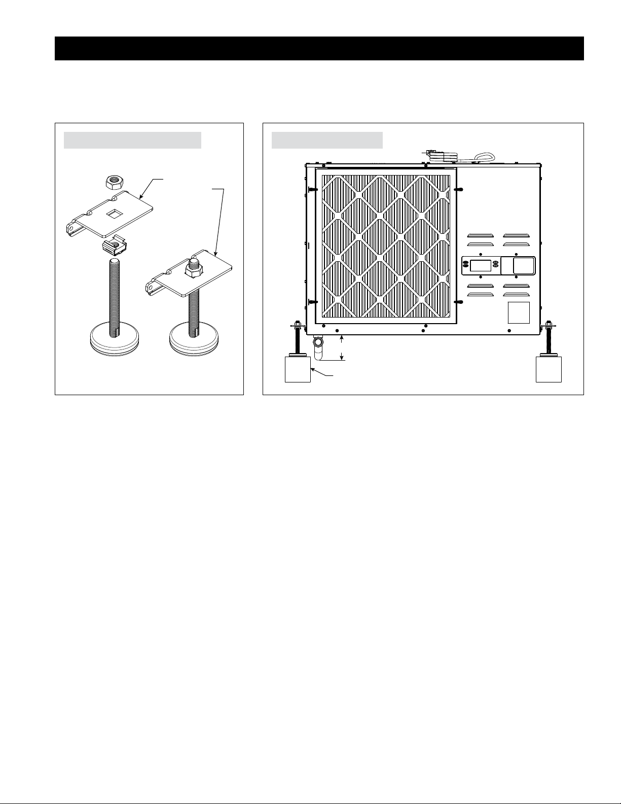
FLOOR MOUNTING � � � � � � � � � � � � � � � � � � � � � � � � � � � � � � � � � � � � � � � � � � � � � � � � � � � � � � � � � � � � � � � � � � � � � � � � � � � � � � � � � � � � � � � � � � � � � � � � � � � � � � � � � � � � � � � � � � � � � � �5
SUSPENDING THE DEHUMIDIFIER � � � � � � � � � � � � � � � � � � � � � � � � � � � � � � � � � � � � � � � � � � � � � � � � � � � � � � � � � � � � � � � � � � � � � � � � � � � � � � � � � � � � � � � � � � � � � � � � � � � � � � � � 6
Install Brackets for Suspending Unit � � � � � � � � � � � � � � � � � � � � � � � � � � � � � � � � � � � � � � � � � � � � � � � � � � � � � � � � � � � � � � � � � � � � � � � � � � � � � � � � � � � � � � � � � � � � � � � � � � � � � 6
Hanging the Dehumidifier� � � � � � � � � � � � � � � � � � � � � � � � � � � � � � � � � � � � � � � � � � � � � � � � � � � � � � � � � � � � � � � � � � � � � � � � � � � � � � � � � � � � � � � � � � � � � � � � � � � � � � � � � � � � � � 6
Ducting� � � � � � � � � � � � � � � � � � � � � � � � � � � � � � � � � � � � � � � � � � � � � � � � � � � � � � � � � � � � � � � � � � � � � � � � � � � � � � � � � � � � � � � � � � � � � � � � � � � � � � � � � � � � � � � � � � � � � � � � � � � � � � � 6
DRAIN INSTALLATION � � � � � � � � � � � � � � � � � � � � � � � � � � � � � � � � � � � � � � � � � � � � � � � � � � � � � � � � � � � � � � � � � � � � � � � � � � � � � � � � � � � � � � � � � � � � � � � � � � � � � � � � � � � � � � � � � � � �7
Condensate Pan, Condensate Pump and Float Switch � � � � � � � � � � � � � � � � � � � � � � � � � � � � � � � � � � � � � � � � � � � � � � � � � � � � � � � � � � � � � � � � � � � � � � � � � � � � � � � � � � � � � �7
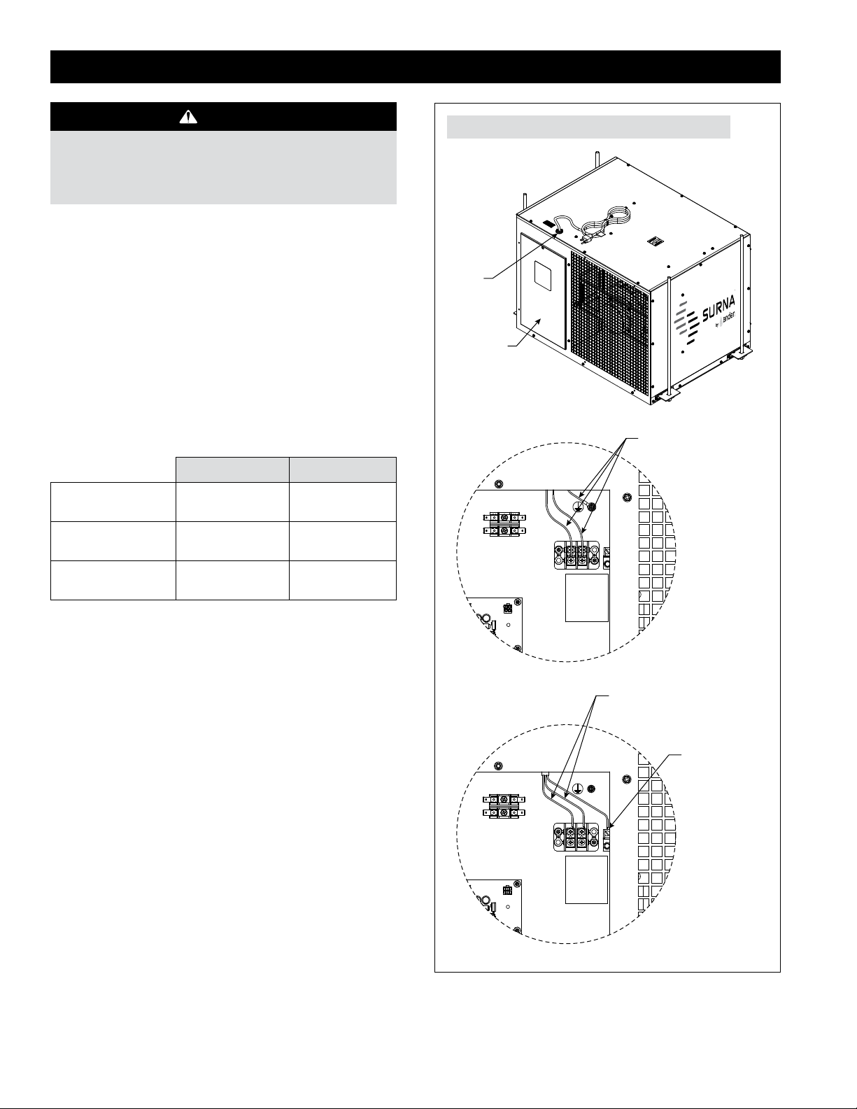
HARD WIRING – LINE VOLTAGE� � � � � � � � � � � � � � � � � � � � � � � � � � � � � � � � � � � � � � � � � � � � � � � � � � � � � � � � � � � � � � � � � � � � � � � � � � � � � � � � � � � � � � � � � � � � � � � � � � � � � � � � � � 8
MODEL S77 – REMOTE CONTROL AND WIRING � � � � � � � � � � � � � � � � � � � � � � � � � � � � � � � � � � � � � � � � � � � � � � � � � � � � � � � � � � � � � � � � � � � � � � � � � � � � � � � � � � � � � � � � � � � 9
Alternate External Controls � � � � � � � � � � � � � � � � � � � � � � � � � � � � � � � � � � � � � � � � � � � � � � � � � � � � � � � � � � � � � � � � � � � � � � � � � � � � � � � � � � � � � � � � � � � � � � � � � � � � � � � � � � � � � 9
SYSTEM SET UP & CHECKOUT � � � � � � � � � � � � � � � � � � � � � � � � � � � � � � � � � � � � � � � � � � � � � � � � � � � � � � � � � � � � � � � � � � � � � � � � � � � � � � � � � � � � � � � � � � � � � � � � � � � � � � � � � � � �10
Installer Test Mode� � � � � � � � � � � � � � � � � � � � � � � � � � � � � � � � � � � � � � � � � � � � � � � � � � � � � � � � � � � � � � � � � � � � � � � � � � � � � � � � � � � � � � � � � � � � � � � � � � � � � � � � � � � � � � � � � � � � � 11
START UP AND SEQUENCE OF OPERATION � � � � � � � � � � � � � � � � � � � � � � � � � � � � � � � � � � � � � � � � � � � � � � � � � � � � � � � � � � � � � � � � � � � � � � � � � � � � � � � � � � � � � � � � � � � � � � � 12
Using the Dehumidifier Control � � � � � � � � � � � � � � � � � � � � � � � � � � � � � � � � � � � � � � � � � � � � � � � � � � � � � � � � � � � � � � � � � � � � � � � � � � � � � � � � � � � � � � � � � � � � � � � � � � � � � � � � �12
Using Model S77 Control � � � � � � � � � � � � � � � � � � � � � � � � � � � � � � � � � � � � � � � � � � � � � � � � � � � � � � � � � � � � � � � � � � � � � � � � � � � � � � � � � � � � � � � � � � � � � � � � � � � � � � � � � � � � � � �12
TROUBLESHOOTING � � � � � � � � � � � � � � � � � � � � � � � � � � � � � � � � � � � � � � � � � � � � � � � � � � � � � � � � � � � � � � � � � � � � � � � � � � � � � � � � � � � � � � � � � � � � � � � � � � � � � � � � � � � � � � � � � � � �13
Table 1 – Diagnostic Codes � � � � � � � � � � � � � � � � � � � � � � � � � � � � � � � � � � � � � � � � � � � � � � � � � � � � � � � � � � � � � � � � � � � � � � � � � � � � � � � � � � � � � � � � � � � � � � � � � � � � � � � � � � � � �13
Table 2 – Troubleshooting Guide � � � � � � � � � � � � � � � � � � � � � � � � � � � � � � � � � � � � � � � � � � � � � � � � � � � � � � � � � � � � � � � � � � � � � � � � � � � � � � � � � � � � � � � � � � � � � � � � � � � � � � � �14
SERVICE PARTS � � � � � � � � � � � � � � � � � � � � � � � � � � � � � � � � � � � � � � � � � � � � � � � � � � � � � � � � � � � � � � � � � � � � � � � � � � � � � � � � � � � � � � � � � � � � � � � � � � � � � � � � � � � � � � � � � � � � � � � � �15
LIMITED WARRANTY � � � � � � � � � � � � � � � � � � � � � � � � � � � � � � � � � � � � � � � � � � � � � � � � � � � � � � � � � � � � � � � � � � � � � � � � � � � � � � � � � � � � � � � � � � � � � � � � � � � � � � � � � � � � � � � � � � � �16
2 English

SPECIFICATIONS
Ø 3/4" FNPT DRAIN
17-5/8
1-11/16
4-7/16
32-11/16
35
37
25 UP TO 1/2" DIAMETER ROD
24
FIGURE 1 – DIMENSIONS (INCHES)
ELECTRICAL S320V1 S320V3
Voltage 208-240 VAC (~), 1ø, 60 HZ 277 VAC (~), 1ø, 60 HZ
Operating Current 11�1A @ 80°F, 60% RH 9�1A @ 80°F, 60% RH
Efficiency 2�9 L/kW-hr (6�0 pints/kW-hr)
@ 80°F, 60% RH
2�6 L/kW-hr (5�5 pints/kW-hr)
@ 80°F, 60% RH
ENVIRONMENTAL
Operating Temperature Range 65°F – 85°F
Operating Dew Point 40°F – 75°F
MECHANICAL
Weight 180 lbs (without packaging)
Drain Size 3/4" FNPT
Capacity 320 PPD @ 80°F, 60% RH
Filter MERV 11
Airflow 830 CFM (free flow)
DIMENSIONS
English 3

UNPACKING THE DEHUMIDIFIER
Use the cut line on the carton to pulll carton off dehumidfier�
INCLUDED IN THE CARTON
• Dehumidifier
• Installation manual
• Hanging brackets
• Model S77 control
• 3/4" P-Trap
• 3/4" MNPT x 3/4" hose barb fitting
• 3/4" MNPT x 3/4" female pipe
• 3/4" FNPT x 3/4" female pipe
• 10 feet of 3/4" clear PVC flexible drain hose
• Terminal screwdriver
• 30 feet of thermostat cable
• MERV 11 filter
6"
MIN.
INLET SIDE
ELECTRICAL
SERVICE PANEL
FIGURE 2 – SPACE CLEARANCES
LOCATION CONSIDERATIONS
This appliance is classified as to not be accessible to the general public�
The dehumidifiers should be spaced evenly throughout the area to be
dehumidified with the following recommendations:
1. Avoid placement where the discharge of one dehumidifier is
pointing toward the inlet of another�
2. Avoid locating the dehumidifier inlet too near a supply register�
Space is not usually available to totally avoid this, but minimizing
the amount of cold air that is discharged to the dehumidifier inlet
will improve moisture removal performance of the dehumidifier�
3. Account for handling dehumidifier condensate by considering drain
or sump pump locations�
4. Leave appropriate room on the drain side of the dehumidifier for
wiring and service�
5. Allow sufficient space near the inlet (6" minimum) to be able to
remove/install a filter� More space ensures no loss of airflow due to
restriction at the inlet�
4 English

INCLUDED WITH
DEHUMIDIFIER
3-1/2"
BLOCKING MUST BE USED FOR P-TRAP CLEARANCE
FIGURE 3 – LEVELING FEET ASSEMBLY FIGURE 4 – FLOOR MOUNTING
FLOOR MOUNTING
The 5789 leveling feet kit (not included) is required for floor mounting� The drain hose must continuously slope downward toward the drain� Use solid
supports as needed to elevate the unit enough to allow for continuous drain slope� Use the adjustable feet to level the unit right to left and front to
back so that unit drains properly�
English 5

SUSPENDING THE DEHUMIDIFIER
INSTALL BRACKETS FOR SUSPENDING UNIT
The brackets are designed to accommodate up to 1/2" threaded rod�
1. Insert bracket into slots on the base� See FIGURE 5�
2. Rotate the bracket up toward the dehumidifier and secure the bracket to the side of the dehumidifier using #12 sheet metal screws (provided)�
See FIGURE 6�
3. Repeat for remaining three brackets�
HANGING THE DEHUMIDIFIER
Use the threaded rod to suspend the unit
from appropriate ceiling structure� The unit
weight is 180 lbs� Install vibration isolators
if located in an area where noise could be
a concern� Level unit right to left and front
to back so that unit drains properly�
DUCTING
Use duct kit part number 5807 for
installing ductwork to the dehumidifier�
Maximum external static pressure is
0�2"w�c�
INSERT BRACKET INTO
OPENINGS ON BOTTOM
OF UNIT – 4 PLACES
ROTATE BRACKET
INTO PLACE AND SECURE
WITH SCREWS PROVIDED
4X VIBRATION
ISOLATORS
(OPTIONAL)
FIGURE 5 – INSTALL MOUNTING BRACKET IN BASE FIGURE 6 – SECURE BRACKET TO DEHUMIDIFIER
FIGURE 7 – SUSPENSION
6 English

DRAIN INSTALLATION
The blower draws air through the
dehumidifier, putting the cabinet under
negative pressure� As a result, the included
P-trap is required for proper draining� The
installed drain fitting on the dehumidifier
is 3/4" FNPT� Use the included fittings to
trap and install the drain� See FIGURE 8�
The drain tubing can be hard pipe or clear
flexible tubing� NOTE: PTFE thread seal
tape is recommended for the threaded
connections and hand tighten only�
Use PVC primer and cement for all slip
fit connections to prevent leaks� After
installing the drain connections, trap, and
tubing, pour enough water (about 2 pints)
into the dehumidifier drain pan to prime
the trap�
CONDENSATE PAN, CONDENSATE PUMP AND FLOAT SWITCH
A condensate pan is recommended when suspending
the dehumidifier over finished areas or product� Adhere
to local codes regarding draining of the condensate
pan� If a condensate pump is needed, install it in the
condensate pan as well�
Install a condensate overflow safety switch (i�e� float
switch) in the condensate pan, remove the factory
installed jumper wire between the Float Switch
terminals on the control and wire the float switch to the
dehumidifier as shown in FIGURE 9� Overflow safety
switches on condensate pumps can be wired to the
Float Switch terminals in a similar fashion�
3/4" MNPT x 3/4" BARB
(INCLUDED)
3/4" FEMALE PIPE x 3/4" FNPT
(INCLUDED)
3/4" MNPT x 3/4" FEMALE PIPE
(INCLUDED)
3/4" FLEXIBLE TUBE
(INCLUDED)
FLOAT
Switch
DH DH
NORMALLY CLOSED
FLOAT SWITCH
FIGURE 8 – DRAIN ASSEMBLY
FIGURE 9 – FLOAT SWITCH WIRING
PVC HARD PIPE
(NOT INCLUDED)
3/4" PIPE x 3/4" PIPE COUPLING
(NOT INCLUDED)
3/4" MNPT x 3/4" FEMALE PIPE
(INCLUDED)
English 7

HARD WIRING – LINE VOLTAGE
CAUTION
If the supply cord is damaged, it must be replaced by the
manufacturer, its service agent or similarly qualified persons in
order to avoid a hazard.
The S320V1 dehumidifier comes with a power cord that has a NEMA
6-20P plug that can simply be plugged into a corresponding NEMA
6-20R receptacle� The S320V3 dehumidifier comes with a power
cord that has a NEMA L7-20P plug that can simply be plugged into a
corresponding NEMA L7-20R receptacle� The plug can be removed and
replaced by hard-wired electrical service if desired�
United States Installation: Make all electrical connections in accordance
with the current edition of the NEC ANSI/NFPA 70 and any local codes
or ordinances that may apply�
Canada Installation: Make all electrical connections in accordance with
the current edition of the Canadian Electrical Code CSA C22�1 and any
local codes or ordinances that may apply�
Model S320V1 Model S320V3
Voltage 208-240 VAC (~),
single phase, 60 Hz
277 VAC (~), single
phase, 60 Hz
Minimum Circuit
Ampacity 15A 15A
Maximum Fuse or
Circuit Breaker Size 25A 25A
1. Disconnect electrical service at the main fuse or circuit breaker�
2. Run electrical service to where the dehumidifier is to be installed
following all required local and national codes and standards�
3. Remove the side panel from the dehumidifier�
4. Loosen the terminal screws securing the power cord wires to the
terminal blocks and ground lug�
5. Use channellock pliers to remove the strain relief and power cord
from the unit� Pinch the side of the strain relief to release it from the
opening in the sheet metal and pull it away from the dehumidifier�
6. Route the service wires through the opening in the dehumidifier and
secure the cable or conduit to the opening in the dehumidifier using
fittings/clamps intended for the conduit/cable used�
7. Insert the black service wire into the L1 terminal and the white
service wire into the L2 terminal� Secure the wires into the terminals
by tightening the terminal screws�
8. Insert the ground wire (bare or green) of the electrical service into
the ground lug and secure it in place by tightening the ground lug
screw�
9. Reattach the side panel to the dehumidifier�
10. Restore electrical service at the fuse or circuit breaker�
CONNECT THE
BARE OR GREEN
GROUND WIRE
TO THE GROUND
LUG AS SHOWN
CONNECT THE LINE (BLK) AND
NUETRAL WIRE (WHT) WIRES
TO THE POWER BLOCK AS SHOWN
DISCONNECT POWER
CORD WIRES
L1 L2 G
ELECTRICAL
SERVICE PANEL
HARD
WIRING
ACCESS
L1 L2 G
FIGURE 10 – HARD WIRING TO REPLACE THE POWER CORD
8 English

MODEL S77 – REMOTE CONTROL AND WIRING
NOTE: Use 18-22 AWG wire for control wiring�
Humidity can be controlled using the internal dehumidifier control, a
Model S77 control or a different external control like a thermostat�
Without an external control, the dehumidifier will turn on its blower for
three minutes every 15, 30 or 45 minutes depending on how often the
unit is set to sample the air� The dehumidifier can also be set to sample
the air continuously (see AIR SAMPLING on page 11)� The blower is
turned on to get a representative reading of the room relative humidity�
A shorter sampling period reduces the duration of any humidity spikes
that might occur when neither the air conditioning nor the dehumidifier
are running� To reduce energy consumption the sampling time can be
set to a longer period�
Installing an external control eliminates the need to run the dehumidifier
blower for sampling as the control is constantly measuring the humidity
close to the canopy� When the humidity level rises above the setting,
the dehumidifier is turned on�
To install the Model S77 control:
1. Unplug the dehumidifier or turn off power to the circuit at the
breaker or fuse�
2. Run a 4-wire thermostat cable (use 18–22 AWG wire) from the Model S77 to the control of the dehumidifier�
3. Trim about 1/4" of insulation from the end of the wires on each end� Insert the wire into the terminals as shown in FIGURE 11 and tighten to
secure�
4. Restore dehumidifier power� There is a delay of three minutes after restoring power before the dehumidifier will respond to the control�
5. Go to REMOTE CONTROL on page 10 to configure the dehumidifier control to respond to the Model S77�
The Model S77 will measure the relative humidity and turn the dehumidifier on and off to control the humidity level to the desired setting� The
humidity setting can be adjusted from the control while the display allows easy access and monitoring of the humidity level in the space� It is
recommended that the Model S77 be mounted at/near canopy height� Shield the Model S77 from direct exposure to HPS or LPS lighting�
Press the ON button on the Model AS77 to turn on the control� The UP/DOWN arrow buttons are used to set the desired humidity setting� At all other
times, the Model S77 will display the measured humidity level� Reference the Model S77 Installation and Operating Instructions for set-up�
ALTERNATE EXTERNAL CONTROLS
An 8800 Series thermostat can be used to control the HVAC equipment, and for dehumidifier control in place of the Model S77� The 8800 Series
thermostat has Wi-Fi capability so the conditions in the room can be monitored at any time from any location� Additionally, up to four remote sensors
can be mounted near the canopy and connected to a single thermostat� The four humidity measurements can be averaged and the thermostat will
turn on the dehumidifier based on the averaged value�
Reference the thermostat Installation Instructions and Owner’s Manual for wiring, set-up and operating details�
+ - A B ODT
SensorRemote
Gh Rf Cf Gs YW
HVAC EQUIP.
DH
DH
R/+
C/-
B
A
MODEL S77 CONTROL
FIGURE 11 – MODEL S77 REMOTE CONTROL WIRING
English 9

SYSTEM SET-UP & CHECKOUT
Skip set up and proceed to INSTALLER TEST MODE on page 11 unless:
• A Model S77 or other external control is to be installed
• changing the air sampling rate
1. Check all wiring�
2. Make sure the wire access cover has been snapped back onto the
on-board control�
3. Plug unit in and turn power switch to ON�
4. The on-board control screen should display OFF�
90-1854
NOTE: If the display backlight is not on, the first button press (any
button) will only turn on the backlight� Press the button a second time
to achieve function�
5. Hold the MODE button on the on-board control for 3 seconds to
enter the Installer Set-up Menu�
6. Navigate through the following screens to set up the dehumidifier
for the installed application�
Use the UP or DOWN arrows to select items and use MODE to
switch to the next set-up option� To exit installer set-up, all options
must be scrolled through using the MODE button�
7. After the installer set up options have been completed, DONE will
blink for 3 seconds and the control will return to the OFF screen�
90-1854
90-1854
REMOTE CONTROL
90-1854
If not installing a Model S77, leave
DISABLED and press MODE to go
to the next screen�
90-1854
If installing a Model S77, press the
UP or DOWN button to change to
ENABLED and then press MODE to
go to the next screen
EXTERNAL CONTROL
90-1854
If using the dehumidifier on-board
control, leave DISABLED and press
MODE to go to the next screen�
90-1854
If using an 8800 Series thermostat
as an external control, use the UP
or DOWN button to select
ENABLED, then press MODE to go
to the next screen�
10 English

AIR SAMPLING
90-1854
Use the UP or DOWN button to
adjust how frequently the
dehumidifier samples the air to
determine whether or not to
dehumidify� Fewer minutes means
the dehumidifier will sample more
frequently to minimize humidity swings, but increases cost to operate
due to more frequent fan operation� Press MODE when done to move to
the next screen�
RH OFFSET
90-1854
An offset can be applied to the
on-board humidity reading to
avoid discrepancies with other
humidity measuring devices in the
home� Use the UP/DOWN arrows
to select an offset from -5% to 5%�
Press MODE to exit the installer
set-up screens�
INSTALLER TEST MODE
If everything is properly wired, the dehumidifier and all of the
wired components will turn on and off during Installer Test
Mode to demonstrate that all are properly operating� Installer
Test Mode lasts for four (4) minutes� If the ON/OFF button is
pressed during test mode, the dehumidifier will exit Installer
Test Mode and return to the OFF screen�
DEHUMIDIFICATION ONLY
90-1854
If the dehumidifier is not
already OFF, press the ON/
OFF button to turn it off�
90-1854
Press and hold the ON/
OFF button and MODE
buttons for 3 seconds� The
measured humidity, AIR
SAMPLING and TEST will
show on the display�
90-1854
After three (3) minutes the
dehumidifier compressor
will turn on and
DEHUMIDIFYING will
replace AIR SAMPLING on
the control screen�
90-1854
After one minute of
compressor operation, all
outputs will turn off and
DONE will blink for 3
seconds and then return to
the OFF screen�
90-1854
English 11

START UP AND SEQUENCE OF OPERATION
USING THE DEHUMIDIFIER CONTROL
1. Press the ON/OFF button to turn the dehumidifier control ON� The display will show the current setting, and the dehumidifier blower will turn on
to start sampling the air�
The setting will be replaced by the measured humidity and “AIR SAMPLING” will show on the display�
2. Use the UP or DOWN button to adjust the humidity setting as desired�
3. After three (3) minutes of sampling, the measured humidity will be compared to the setting:
a. If the humidity is above the setting, the dehumidifier compressor turns on and “AIR SAMPLING” will be replaced by “DEHUMIDIFYING”� The
compressor remains on until the measured humidity falls 3% RH below the setting�
b. If the measured humidity is below the setting, the blowers turn off and the display returns to showing the RH setting�
4. The dehumidifier will sample again after the number of minutes selected during the Air Sampling portion of the System Set Up (see page 11), or
any time the humidity setting is lowered�
USING THE MODEL S77 CONTROL
1. Press the ON/OFF button to turn the dehumidifier control ON� “REMOTE” will show on the display to indicate that an external control is wired to
the dehumidifier�
2. At the Model S77, press the ON button; the Model S77 will display the measured RH�
3. Use the UP or DOWN button on the Model S77 to adjust the humidity setting as desired�
4. If the RH measured by the Model S77 rises above the setting, the dehumidifier will turn on� “DEHUMIDIFYING” will appear on the dehumidifier
control display to show that the Model S77 is calling for dehumidification� The dehumidifier will turn off when the RH measured by the Model S77
drops 3% RH below the setting�
12 English

TABLE 1 – DIAGNOSTIC CODES
Diagnostic
Code Failure Mode Action Reset
E1 Internal Humidity or
Temperature Sensor
Open or Shorted
1. If connection okay, replace User Interface, Part No� 5738� Cycle Power
E3 Model S77
Remote Control
Communication Loss
1. Check connections between Model S77 and dehumidifier control board� Terminals should be fully
inserted and secured in the control board and Model S77 control terminals�
2. If connections are correct and secure, turn off the dehumidifier and remove the Model S77� Use a
short section of 4-wire cable to reconnect the Model S77 to the control board� Turn the dehumidifier
back on and increase the dryness level setting on the Model S77� If the dehumidifier turns on, the
problem is with the wiring between the dehumidifier and control�
3. If the dehumidifier does not turn on, call Technical Support�
Self-Correcting
E4 Insufficient Capacity 1. Check the frost sensor connection at the power board� Terminal should be fully seated on the power
board pins�
2. Remove the side access panel and verify that the sensor is secured to the suction line�
3. If the sensor is connected and secured to the refrigeration line proceed to the next step�
4. Reset the fault by cycling power to the dehumidifier�
5. Turn the humidity setting down (below room/home humidity level) to make a dehumidification call�
6. Allow the fan and compressor to run for approximately 10-15 minutes and then enter diagnostic
test mode by simultaneously pressing the UP ARROW and MODE buttons for 3 seconds� The LCD
will display the temperature measured by the internal sensor while also displaying AIR SAMPLING
and ON, the humidity measured by the internal sensor while also displaying %RH and ON, and the
frost sensor temperature while also displaying ON� Scroll through these values and by using the UP/
DOWN arrow buttons�
7. Record values and call Technical Support�
Cycle Power
E5 High Temperature
Thermistor Failure
1. Check the high temperature sensor connection at the power board� Terminal should be fully seated
on the power board pins�
2. Remove the side access panel and verify the sensor is not damaged and connected to the
refrigeration line coming from the compressor�
3. If the sensor is connected and secured to the refrigeration line, it may need to be replaced with Part
No� 5456 – contact Technical Support to confirm�
Cycle Power
E6 Low Temperature
Thermistor Failure
1. Check the low temperature sensor connection at the power board�
2. Remove the side access panel and verify the sensor is not damaged and connected to the suction line�
3. If the sensor is connected and secured to the refrigeration line, it may need to be replaced with Part
No� 5455 – contact Technical Support to confirm�
Self-Correcting
E7 Float Switch Open 1. Empty the condensate pan�
2. Check the float switch connection at the control board�
3. If not using a float switch, verify jumper is between float switch terminals on dehumidifier control board�
4. If the problem persists, replace the float switch�
Self-Correcting
E8 Inlet Air Temperature
Out of 50°F – 104°F
Range or Dew Point
Below 40°F
1. Verify all ductwork is properly sealed�
2. If no signs of leak points, contact Technical Support�
Self-Correcting
TROUBLESHOOTING
Technical Support is available Monday through Friday, 7:00 a�m� to 5:00 p�m� CST, at (800) 972-3710� Use the guides on the following pages to identify
and correct system faults� Contact Technical Support before replacing the unit or any components and for additional troubleshooting�
DIAGNOSTIC CODES
When an error occurs, the Diagnostic Code along with SERVICE REQUIRED will be displayed on the control
screen� If a 5818 Alert Light is used, the light will turn on when an error occurs�
90-1854
English 13

TABLE 2 – TROUBLESHOOTING GUIDE
Symptom Possible Reason Troubleshooting Procedure
Dehumidifier does not
turn on/run�
No power to unit� • Check that the dehumidifier is plugged in�
• Check that the power switch is turned ON�
• Check that the control is turned ON�
• Check that the circuit breaker has not tripped�
Dehumidifier blower is
running but with little or
no airflow�
Pressure drop across
dehumidifier is too high�
• Check dehumidifier air filter and replace if necessary�
• Check for blocked duct work and clear�
Dehumidifier blower is
running but compressor
is not�
Float switch open� • If float switch installed, check connections at control board and empty condensate pan�
• If no float switch installed check that the jumper is installed at the float switch terminals on the control
board�
Coil frosting – defrost� • Lack of or reduced airflow� Check dehumidifier air filter and replace if necessary�
• Check for blocked duct work�
• Inlet air conditions below 60°F� Increase the humidity setting�
Inlet air temperature is
outside of the 50°F –
104°F range or the dew
point is below 40°F and
there is a demand for
dehumidification�
• Verify all ductwork is properly sealed�
Dehumidifier is not
draining properly�
Drain line blocked or unit
not level�
• Verify that the unit is level�
• Check the drain line blockages and for a continuous downward slope�
Dehumidifier is
producing hot air�
Normal function� • Air is reheated across the condenser coil, resulting in a temperature rise between inlet and outlet, this is
normal�
14 English

SERVICE PARTS
No. Part Description Part No.
1Transformer, 40VA, 240V (V1) 5784
Transformer, 40VA, 277V (V3) 5808
2Fuse, 1A, Slow-Blow 5785
3Internal Power PCB 5444
4Compressor Contactor 5714
5Compressor Run Capacitor (45MFD, 370VAC) (V1) 5458
Compressor Run Capacitor (60MFD, 370VAC) (V3) 5809
6Fan Relay 5787
7Fan Assembly 5810
8Cord, SJT 12/3, 6-20P (V1) 5811
Cord, SJT 12/3, L7-20P (V3) 5812
9Filter, MERV 11 5813
No. Part Description Part No.
10 User Interface 5738
11 Low Temperature Sensor 5814
12 High Temperature Sensor 5815
Not Shown
Digital Dehumidifier Control S77
P-Trap Kit 5816
Fitting, 3/4" MNPT x 3/4" BARB, PVC 5693
Drain Tubing, 3/4" ID x 10' L 5740
Duct Kit 5807
Leveling Feet 5789
Alert Light 5818
Hanging Bracket Kit 5819
71
2
3
4
8
56
12
11
10
9
English 15

surna.com
1780 55th Street
Boulder, CO 80301
+1 (303) 993-5271
LIMITED WARRANTY
Your Research Products Corporation Anden™ Dehumidifier is expressly warranted for five (5) years from date of installation to be free from defects in materials or workmanship�
Research Products Corporation’s exclusive obligation under this warranty shall be to supply, without charge, a replacement for any component which is found to be defective within such
five (5) year period and which is returned not later than thirty (30) days after said five (5) year period by you to either your original supplier or to Research Products Corporation, Madison,
Wisconsin 53701, together with the model number and installation date of the dehumidifier�
THIS WARRANTY SHALL NOT OBLIGATE RESEARCH PRODUCTS CORPORATION FOR ANY LABOR COSTS AND SHALL NOT APPLY TO DEFECTS IN WORKMANSHIP OR MATERIALS
FURNISHED BY YOUR INSTALLER AS CONTRASTED TO DEFECTS IN THE DEHUMIDIFIER ITSELF�
IMPLIED WARRANTIES OF MERCHANTABILITY OR FITNESS FOR A PARTICULAR PURPOSE SHALL BE LIMITED IN DURATION TO THE AFORESAID FIVE YEAR PERIOD� RESEARCH PRODUCTS
CORPORATION’S LIABILITY FOR INCIDENTAL OR CONSEQUENTIAL DAMAGES, OTHER THAN DAMAGES FOR PERSONAL INJURIES, RESULTING FROM ANY BREACH OF THE AFORESAID
IMPLIED WARRANTIES OR THE ABOVE LIMITED WARRANTY IS EXPRESSLY EXCLUDED� THIS LIMITED WARRANTY IS VOID IF DEFECT(S) RESULT FROM FAILURE TO HAVE THIS UNIT
INSTALLED BY A QUALIFIED HEATING AND AIR CONDITIONING CONTRACTOR� IF THE LIMITED WARRANTY IS VOID DUE TO FAILURE TO USE A QUALIFIED CONTRACTOR, ALL DISCLAIMERS
OF IMPLIED WARRANTIES SHALL BE EFFECTIVE UPON INSTALLATION�
Some states do not allow limitations on how long an implied warranty lasts or the exclusion or limitation of incidental or consequential damages so the above exclusion or limitations may
not apply to you�
This warranty gives you specific legal rights and you may also have other rights which vary from state to state�
WARRANTY REGISTRATION
Visit us online at anden.com to register your Anden product� If you do not have online access, please mail a postcard with your name, address, phone number, email address, product
purchased, model number, date of purchase, and dealer name and address to: Research Products Corporation, P�O� Box 1467, Madison, WI 53701�
Your warranty registration information will not be sold or shared outside of this company.
16 English

COMMANDE DU DÉSHUMIDIFICATEUR
ADMISSION
FILTRE
SORTIE
BOUTON ON/OFF (MARCHE/
ARRÊT) POUR METTRE EN
MARCHE ET ÉTEINDRE LE
DÉSHUMIDIFICATEUR
BOUTONS UP/DOWN
(FLÈCHES VERS LE HAUT
ET VERS LE BAS) POUR
AJUSTER LE RÉGLAGE
DE L’HUMIDITÉ
BOUTON MODE POUR
LES OPTIONS
DIRECTIVES RELATIVES À LA SÉCURITÉ
AVERTISSEMENT
1. La tension élevée peut causer des blessures graves en raison d'un choc électrique. Débranchez l’alimentation électrique avant de commencer
l’installation ou l’entretien. Laissez l’alimentation débranchée jusqu’à ce que l’installation ou l’entretien soit terminé(e).
2. Les bords acérés peuvent causer des coupures graves. Restez prudent pendant la découpe des ouvertures de la chambre de répartition d’air
et le travail sur les gaines d’interconnexion.
3. Le fait de laisser tomber l’appareil peut causer des blessures ou des dommages matériels. Manipulez avec précaution et respectez les
directives d’installation.
MISE EN GARDE
1. Lisez les directives au complet avant de commencer l’installation.
2. Cet appareil n’est pas prévu pour être utilisé par des personnes (y compris des enfants) dont les capacités physiques, sensorielles ou
mentales sont diminuées ou n’ayant ni l’expérience ni les connaissances requises, à moins qu’ils ne soient étroitement surveillés ou qu’ils
aient reçu des consignes concernant l’usage sécuritaire de l’appareil par la personne chargée de leur sécurité. Faites en sorte de surveiller les
enfants pour vous assurer qu’ils ne jouent pas avec cet appareil.
3. N’utilisez pas cet appareil près de piscines. Les produits chimiques utilisés dans les piscines pourraient endommager le déshumidificateur.
4. N’utilisez ni solvants, ni produits de nettoyage sur ou à proximité de la carte de circuits imprimés. Les produits chimiques pourraient
endommager ses composants.
5. Veuillez attendre 24 heures après réception avant de mettre l’appareil en marche s’il n’a pas été expédié ou rangé en position debout.
6. Si le cordon d’alimentation a été endommagé, il doit être remplacé par le fabricant, un de ses prestataires de service ou des personnes
également qualifiées pour éviter tout danger.
LIRE ET CONSERVER CES DIRECTIVES
Déshumidificateur
Modèle S320V1 et Modèle S320V3
Directives d’installation et mode d’emploi
9.19 Français 1

TABLE DES MATIÈRES
DIRECTIVES RELATIVES À LA SÉCURITÉ � � � � � � � � � � � � � � � � � � � � � � � � � � � � � � � � � � � � � � � � � � � � � � � � � � � � � � � � � � � � � � � � � � � � � � � � � � � � � � � � � � � � � � � � � � � � � � � � � � � 1
SPÉCIFICATIONS � � � � � � � � � � � � � � � � � � � � � � � � � � � � � � � � � � � � � � � � � � � � � � � � � � � � � � � � � � � � � � � � � � � � � � � � � � � � � � � � � � � � � � � � � � � � � � � � � � � � � � � � � � � � � � � � � � � � � � � � �3
RETRAIT DE L’EMBALLAGE DU DÉSHUMIDIFICATEUR� � � � � � � � � � � � � � � � � � � � � � � � � � � � � � � � � � � � � � � � � � � � � � � � � � � � � � � � � � � � � � � � � � � � � � � � � � � � � � � � � � � � � � 4
CONSIDÉRATIONS RELATIVES À L’EMPLACEMENT� � � � � � � � � � � � � � � � � � � � � � � � � � � � � � � � � � � � � � � � � � � � � � � � � � � � � � � � � � � � � � � � � � � � � � � � � � � � � � � � � � � � � � � � � 4
FIXATION SUR LE SOL � � � � � � � � � � � � � � � � � � � � � � � � � � � � � � � � � � � � � � � � � � � � � � � � � � � � � � � � � � � � � � � � � � � � � � � � � � � � � � � � � � � � � � � � � � � � � � � � � � � � � � � � � � � � � � � � � � � �5
SUSPENDRE LE DÉSHUMIDIFICATEUR � � � � � � � � � � � � � � � � � � � � � � � � � � � � � � � � � � � � � � � � � � � � � � � � � � � � � � � � � � � � � � � � � � � � � � � � � � � � � � � � � � � � � � � � � � � � � � � � � � � � 6
Installer les supports pour suspendre l’appareil � � � � � � � � � � � � � � � � � � � � � � � � � � � � � � � � � � � � � � � � � � � � � � � � � � � � � � � � � � � � � � � � � � � � � � � � � � � � � � � � � � � � � � � � � � � 6
Suspendre le déshumidificateur� � � � � � � � � � � � � � � � � � � � � � � � � � � � � � � � � � � � � � � � � � � � � � � � � � � � � � � � � � � � � � � � � � � � � � � � � � � � � � � � � � � � � � � � � � � � � � � � � � � � � � � � � 6
Conduites� � � � � � � � � � � � � � � � � � � � � � � � � � � � � � � � � � � � � � � � � � � � � � � � � � � � � � � � � � � � � � � � � � � � � � � � � � � � � � � � � � � � � � � � � � � � � � � � � � � � � � � � � � � � � � � � � � � � � � � � � � � � � 6
INSTALLATION DE L’ÉVACUATION � � � � � � � � � � � � � � � � � � � � � � � � � � � � � � � � � � � � � � � � � � � � � � � � � � � � � � � � � � � � � � � � � � � � � � � � � � � � � � � � � � � � � � � � � � � � � � � � � � � � � � � � �7
Bac à condensats, pompe à condensats et interrupteur du flotteur � � � � � � � � � � � � � � � � � � � � � � � � � � � � � � � � � � � � � � � � � � � � � � � � � � � � � � � � � � � � � � � � � � � � � � � � � �7
CÂBLAGE DIRECT – TENSION DE LA LIGNE � � � � � � � � � � � � � � � � � � � � � � � � � � � � � � � � � � � � � � � � � � � � � � � � � � � � � � � � � � � � � � � � � � � � � � � � � � � � � � � � � � � � � � � � � � � � � � � 8
MODÈLE S77 – COMMANDE À DISTANCE ET CÂBLAGE� � � � � � � � � � � � � � � � � � � � � � � � � � � � � � � � � � � � � � � � � � � � � � � � � � � � � � � � � � � � � � � � � � � � � � � � � � � � � � � � � � � � � 9
Commandes externes alternatives� � � � � � � � � � � � � � � � � � � � � � � � � � � � � � � � � � � � � � � � � � � � � � � � � � � � � � � � � � � � � � � � � � � � � � � � � � � � � � � � � � � � � � � � � � � � � � � � � � � � � � � 9
CONFIGURATION & VÉRIFICATION DU SYSTÈME � � � � � � � � � � � � � � � � � � � � � � � � � � � � � � � � � � � � � � � � � � � � � � � � � � � � � � � � � � � � � � � � � � � � � � � � � � � � � � � � � � � � � � � � � �10
Mode d’essai de l’installateur � � � � � � � � � � � � � � � � � � � � � � � � � � � � � � � � � � � � � � � � � � � � � � � � � � � � � � � � � � � � � � � � � � � � � � � � � � � � � � � � � � � � � � � � � � � � � � � � � � � � � � � � � � � 11
DÉMARRAGE ET SÉQUENCE DE FONCTIONNEMENT � � � � � � � � � � � � � � � � � � � � � � � � � � � � � � � � � � � � � � � � � � � � � � � � � � � � � � � � � � � � � � � � � � � � � � � � � � � � � � � � � � � � � � �12
À l’aide de la commande du déshumidificateur� � � � � � � � � � � � � � � � � � � � � � � � � � � � � � � � � � � � � � � � � � � � � � � � � � � � � � � � � � � � � � � � � � � � � � � � � � � � � � � � � � � � � � � � � � �12
À l’aide de la commande modèle S77� � � � � � � � � � � � � � � � � � � � � � � � � � � � � � � � � � � � � � � � � � � � � � � � � � � � � � � � � � � � � � � � � � � � � � � � � � � � � � � � � � � � � � � � � � � � � � � � � � � �12
DÉPANNAGE����������������������������������������������������������������������������������������������������������������������������13
Tableau 1 – Codes de diagnostic � � � � � � � � � � � � � � � � � � � � � � � � � � � � � � � � � � � � � � � � � � � � � � � � � � � � � � � � � � � � � � � � � � � � � � � � � � � � � � � � � � � � � � � � � � � � � � � � � � � � � � � � 13
Tableau 2 – Guide de dépannage � � � � � � � � � � � � � � � � � � � � � � � � � � � � � � � � � � � � � � � � � � � � � � � � � � � � � � � � � � � � � � � � � � � � � � � � � � � � � � � � � � � � � � � � � � � � � � � � � � � � � � �14
PIÈCES DE RECHANGE�������������������������������������������������������������������������������������������������������������������15
GARANTIE LIMITÉE��������������������������������������������������������������������������������������������������������������������� 16
2 Français

SPÉCIFICATIONS
Ø 1,91 (3/4 po) DRAIN FNPT
44,77 (17-5/8)
4,29 (1-11/16)
11,27 (4-7/16)
83,03
(32-11/16)
88,90
(35)
93,99
(37)
63,50 (25) TIGE 1,27 cm (1/2 po) DE DIAMÈTRE MAX
60,96 (24)
FIGURE 1 – DIMENSIONS cm (po)
DIMENSIONS
ÉLECTRICITÉ S320V1 S320V3
Tension 208-240 V c�a� (~), 1ø, 60 HZ 277 V c�a� (~), 1ø, 60 HZ
Courant de
fonctionnement 11,1 A @ 27°C (80°F), 60% d’HR 9,1 A @ 27°C (80°F), 60% d’HR
Efficacité 2,9 L/kWh (6,0 pintes/kWh)
@ 27°C (80°F), 60% d’HR
2,6 L/kWh (5,5 pintes/kWh)
@ 27°C (80°F), 60% d’HR
ENVIRONNEMENT
Plage de températures
de fonctionnement 18 à 29°C (65 à 85°F)
Point de rosée de service 7 à 24°C (40 à 75°F)
MÉCANIQUE
Poids 81,6 kg (180 lb)
(sans emballage)
Dimension de l’évacuation FNPT 19 mm (3/4 po)
Capacité 320 PPD @ 27°C
(80°F), 60% d’HR
Filtre MERV 11
Circulation d’air 830 CFM (libre)
Français 3

RETRAIT DE L’EMBALLAGE DU DÉSHUMIDIFICATEUR
Suivez la ligne de découpe sur le carton pour dégager le déshumidificateur du carton�
CONTENU DU CARTON
• Déshumidificateur
• Manuel d’installation
• Support de suspension
• Commande du modèle S77
• Siphon en P 19 mm (3/4 po)
• Raccord pour flexible cannelé 19 mm (3/4 po) MNPT x 19 mm (3/4po)
• Conduite femelle 19 mm (3/4 po) MNPT x 19 mm (3/4po)
• Conduite femelle 19 mm (3/4 po) FNPT x 19 mm (3/4po)
• 3 m de tuyau d’évacuation en PVC transparent de 19 mm (3/4 po)
• Tournevis pour bornier
• 9 m de câble de thermostat
• Filtre MERV 11
PANNEAU DE
SERVICE ÉLECTRIQUE
15,2 cm
(6 po)
MIN.
COTÉ ADMISSION
FIGURE 2 – DÉGAGEMENTS
CONSIDÉRATIONS RELATIVES À L’EMPLACEMENT
Cet appareil a été classé dans la catégorie «ne doit pas être accessible
au grand public»� Les déshumidificateurs devraient être placés à
intervalles réguliers dans toute la zone à déshumidifier en tenant
compte des considérations suivantes :
1. Évitez de les placer de telle sorte que l’évacuation d’un
déshumidificateur soit dirigée vers l’admission d’un autre�
2. Évitez de placer l’admission d’un déshumidificateur trop près
d’un registre d’air� En principe, on n’a pas suffisamment de
place pour éviter cette situation, mais le fait de minimiser au
possible la quantité d’air froid qui est déchargée dans l’admission
du déshumidificateur permettra d’améliorer le rendement du
déshumidificateur en terme d’élimination de l’humidité�
3. Pensez à comment vous évacuerez les condensats du
déshumidificateur et considérez un emplacement près d’une
conduite d’évacuation ou d’une pompe de puisard�
4. Laissez suffisamment de place sur le côté de l’évacuation du
déshumidificateur pour prévoir le câblage et l’entretien�
5. Laissez suffisamment de place près de l’admission (15,2 cm (6po)
minimum) pour pouvoir déposer et installer un filtre� S’il y a plus
de place, il n’y n’aura aucune perte de débit d’air du fait des
obstructions au niveau de l’admission�
6"
MIN.
INLET SIDE
ELECTRICAL
SERVICE PANEL
4 Français
This manual suits for next models
1
Table of contents
Languages:
Other Anden Dehumidifier manuals