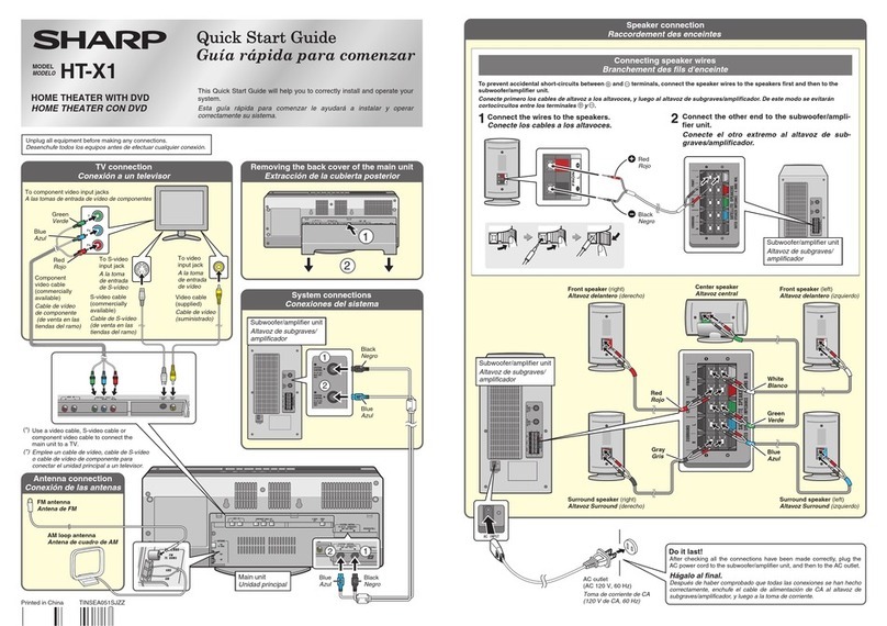
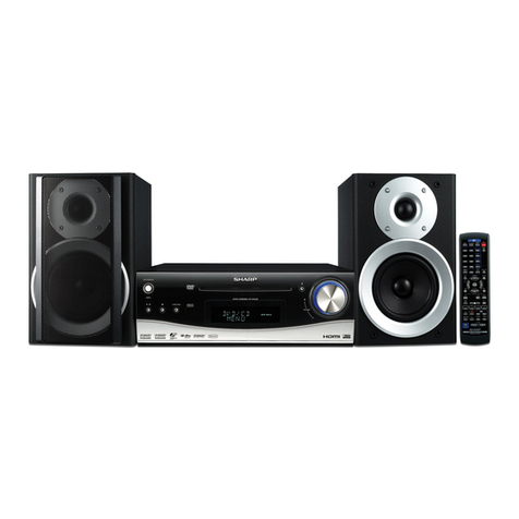
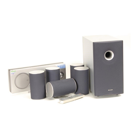
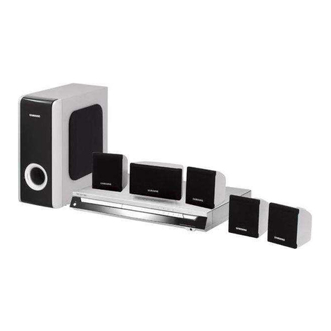
Sharp SD-AS10H(S) User manual

SD-AS10H
SERVICE MANUAL
SHARP CORPORATION
CONTENTS
Parts marked with " " are important for maintaining the safety of the set. Be sure to replace these parts with specified ones for
maintaining the safety and performance of the set.
This document has been published to be used
for after sales service only.
The contents are subject to change without notice.
CHAPTER 1. GENERAL DESCRIPTION
[1] Specifications.................................................1-1
[2] Names of parts...............................................1-2
CHAPTER 2. ADJUSTMENTS
[1] 1-bit section....................................................2-1
[2] DVD/CD section.............................................2-1
[3] TEST Mode.................................................... 2-1
[4] Description on the Circuits of the 1-Bit Unit
(See the wiring diagrams on pages 6-23, 6-
24.).................................................................2-7
[5] Confirming and Canceling the Detection
Line of the Protect Circuit...............................2-7
[6] Protect Circuit Explanation.............................2-8
CHAPTER 3. MECHANISM BLOCKS
[1] Caution on disassembly.................................3-1
[2] DVD Changer mechanism section.................3-5
CHAPTER 4. DIAGRAMS
[1] Block diagram ................................................4-1
CHAPTER 5. CIRCUIT DESCRIPTION
[1] Notes on schematic diagram.........................5-1
[2] Types of transistor and LED ..........................5-1
[3] Waveforms of 1-BIT circuit ............................5-2
[4] Waveforms of DVD circuit..............................5-3
[5] Voltage...........................................................5-5
CHAPTER 6. CIRCUIT SCHEMATICS AND PARTS
LAYOUT
[1] Wiring side of PWB........................................6-1
[2] Schematic diagram......................................6-13
CHAPTER 7. FLOWCHART
[1] Troubleshooting.............................................7-1
CHAPTER 8. OTHER
[1] Function table of IC .......................................8-1
Parts Guide
In the interests of user-safety the set should be restored to its
original condition and only parts identical to those specified be
used.
No. S3519SDAS10HS
SD-AS10H(S)
1-BIT DIGITAL HOME CINEMA WITH DVD
MODEL
SD-AS10H(S) 1-Bit Digital Home Cinema with DVD consisting
of SD-AS10H(S) (main unit and amplifier unit), CP-AS10HF
(front speakers), CP-AS10HC (center speaker), CP-AS10HR
(surround speakers) and CP-AS10HSW (subwoofer).

SD-AS10H
– i –
[1] Safety precaution for service manual
Precaution to be taken when replacing and servicing the
Laser Pickup.
The AEL (Accessible Emission Level) of Laser Power Output
for this model is specified to be lower than Class 1 Require-
ments. However, the following precautions must be observed
during servicing to protect your eyes against exposure to the
Laser beam.
(1) When the cabinet has been removed, the power is turned
on without a compact disc, and the Pickup is on a position
outer than the lead-in position, the Laser will light for sev-
eral seconds to detect a disc. Do not look into the Pickup
Lens.
(2) The Laser Power Output of the Pickup inside the unit and
replacement service parts have already been adjusted prior
to shipping.
(3) No adjustment to the Laser Power should be attempted
when replacing or servicing the Pickup.
(4) Under no circumstances look directly into the Pickup Lens
at any time.
(5) CAUTION - Use of controls or adjustments, or performance
of procedures other than those specified herein may result
in hazardous radiation exposure.
[2] Important service notes (For U.K. only)
Before returning the unit to the customer after completion of a
repair or adjustment it is necessary for the following withstand
voltage test to be applied to ensure the unit is safe for the cus-
tomer to use.
Setting of Withstanding Voltage Tester and set.
Set name set value
Withstanding Voltage Tester
Test voltage 4.7 kV DC
Set time 3 secs
Set current (Cutoff current) 3 mA
Unit
Judgment
OK: The "GOOD" lamp lights.
NG: The "NG" lamp lights and the buzzer sounds.
PROBE
AC
OUT
UNIT
SHORT-CIRCUIT
AC POWER
SUPPLY CORD
CONNECT THE PROBE
TO GND OF CHASSIS
SCREW
WITHSTANDING
VOLTAGE TESTER

SD-AS10H
– ii –
PRECAUTIONS FOR USING LEAD-FREE SOLDER
1. Employing lead-free solder
"All PWBs" of this model employs lead-free solder. The LF symbol indicates lead-free solder, and is attached on the PWBs and service manuals. The
alphabetical character following LF shows the type of lead-free solder.
Example:
Indicates lead-free solder of tin, silver and copper.
2. Using lead-free wire solder
When fixing the PWB soldered with the lead-free solder, apply lead-free wire solder. Repairing with conventional lead wire solder may cause damage
or accident due to cracks.
As the melting point of lead-free solder (Sn-Ag-Cu) is higher than the lead wire solder by 40 °C, we recommend you to use a dedicated soldering bit,
if you are not familiar with how to obtain lead-free wire solder or soldering bit, contact our service station or service branch in your area.
3. Soldering
As the melting point of lead-free solder (Sn-Ag-Cu) is about 220 °C which is higher than the conventional lead solder by 40 °C, and as it has poor
solder wettability, you may be apt to keep the soldering bit in contact with the PWB for extended period of time. However, Since the land may be
peeled off or the maximum heat-resistance temperature of parts may be exceeded, remove the bit from the PWB as soon as you confirm the steady
soldering condition.
Lead-free solder contains more tin, and the end of the soldering bit may be easily corrected. Make sure to turn on and off the power of the bit as
required.
If a different type of solder stays on the tip of the soldering bit, it is alloyed with lead-free solder. Clean the bit after every use of it.
When the tip of the soldering bit is blackened during use, file it with steel wool or fine sandpaper.
Be careful when replacing parts with polarity indication on the PWB silk.
Lead-free wire solder for servicing
Ref No. Parts No. Description
PWB-A 92LPWB5888MANS Main/Speaker terminal/LED A/LED B
PWB-B 92LPWB5888PWRS Power/1-Bit Amp.
PWB-C 92LPWB5888DPLS Display/Terminal B
PWB-D 92LPWB5880MCAS Sensor A/Switch B/Drum Motor/Switch C/Sensor B
PWB-F 92LPWB5888JCKS Terminal A

SD-AS10H
1 – 1
AudioSD-AS10HService ManualSD-AS10HMarketE
CHAPTER 1. GENERAL DESCRIPTION
[1] Specifications
Amplifier unit
Power source AC 230 V, 50 Hz
Power consumption Power on: 87 W
Power stand-by: 1.0 W
Dimensions Width: 430 mm (16-15/16")
Height: 60 mm (2-3/8")
Depth: 321 mm (12-11/16")
Weight 3.9 kg (8.6 lbs.)
Speaker terminals Front speakers, centre speaker, surround speakers and
subwoofer: more than 4 ohms
Audio output
terminals
Headphones: 16 - 50 ohms (recommended: 32 ohms)
Optical digital output: Square type 1
Audio output (VCR): RCA type 1 pair (L/R)
Subwoofer Pre Out: RCA type 1
Audio input terminals Audio input (TV, VCR): RCA type 2 pairs (L/R)
Coaxial digital input: RCA type 1
Optical digital input: Square type 1
Other terminals System control 1
Amplification system 5.6448 MHz (128 fs) 1-bit switching
(remarks: fs = 44.1 kHz)
Rated power output Front: 100W+100W,Centre: 100 W (DIN 45 324)
Surround: 100 W + 100 W (4 ohms at 1 kHz) (DIN 45 324)
Subwoofer: 100 W (4 ohms at 100 Hz) (DIN 45 324)
A/D noise shaping 7th-order (delta - sigma) modulation
Frequency
characteristics
Linear PCM DVD:
4 Hz to 22 kHz (sampling rate: 48 kHz)
4 Hz to 44 kHz (sampling rate: 96 kHz)
CD: 4 Hz to 20 kHz
S/N ratio CD: 96 dB (1 kHz)
Dynamic range Linear PCM DVD: 95 dB
CD: 94 dB
Total harmonic
distortion ratio
0.006 % maximum
Frequency range FM: 87.5 - 108 MHz
AM: 522 - 1,620 kHz
Type Twin-drive speaker system (magnetically shielded)
8 cm (3-1/8") speaker 2
Maximum input power 100 W
Impedance 4 ohms
Dimensions Width: 168 mm (6-5/8")
Height: 195 mm (7-11/16")
Depth: 81 mm (3-3/16")
Weight 1.5 kg (3.3 lbs.)/each
Type Twin-drive speaker system (magnetically shielded)
8 cm (3-1/8") speaker 2
Maximum input power 100 W
Impedance 4 ohms
Dimensions Width: 168 mm (6-5/8")
Height: 195 mm (7-11/16")
Depth: 81 mm (3-3/16")
Weight 1.5 kg (3.3 lbs.)/each
Type Twin-drive speaker system (magnetically shielded)
8 cm (3-1/8") speaker 2
Maximum input power 100 W
Impedance 4 ohms
Dimensions Width: 430 mm (16-15/16")
Height: 100 mm (3-15/16")
Depth: 81 mm (3-3/16")
Weight 1.7 kg (3.8 lbs.)
Type Single speaker system
16 cm (6-1/2") woofer 1
Maximum input power 100 W
Impedance 4 ohms
Dimensions Width: 300 mm (11-13/16")
Height: 295 mm (11-5/8")
Depth: 359 mm (14-3/16")
Weight 6.2 kg (13.7 lbs.)
FOR A COMPLETE DESCRIPTION OF THE OPERATION OF THIS UNIT, PLEASE REFER TO
THE OPERATION MANUAL.
Specifications for this model are subject to change without prior
notice
SD-AS10H
CP-AS10HF
CP-AS10HR
CP-AS10HC
CP-AS10HSW
Main unit (DVD player unit)
Dimensions Including the stand Width: 430 mm (16-15/16")
Height: 228 mm (9")
Depth: 150 mm (5-15/16")
Excluding the stand Width: 430 mm (16-15/16")
Height: 195 mm (7-11/16")
Depth: 86 mm (3-7/16")
Weight DVD player unit: 3.0 kg (6.6 lbs.)
Stand: 0.8 kg (1.8 lbs.)
Video output
terminals
SCART output: SCART terminal 1
Video output: RCA type 1
S-video output: S-terminal 1
Component video output: RCA type 3 (Y/PB/PR)
Other terminals System control 1
Signal system PAL/NTSC colour
Supported disc types DVD-Video (region number 2 or ALL), DVD-R/RW (video
mode), SVCD, VCD, audio CD, CD-R, CD-RW
Video signal Horizontal resolution: 500 lines
S/N ratio: 65 dB

SD-AS10H
1 – 2
[2] Names of parts
Main unit
1. Disc Number Select Buttons
2. Disc Compartment Open/Close Button
3. Function Button
4. Tuner (Band) Button
5. Play Button
6. Stop Button
7. Chapter (Track) Skip Up and Down,
Search or Tuning Up and Down buttons
8. Volume Up and Down Buttons
9. Remote Sensor
10. On/Stand-by Button
11. Timer Set Indicator
12. Disc Compartment
13. Main Unit Stand
14. Function Indicator
15. Track, Title, Chapter, Total Information Indicator
16. Time and Present Disc Indicator
17. Speaker Indicators
18. Operation Indicator
19. Progressive Scan Mode Indicator
20. Audio Signal Indicator
21. Surround Indicator
22. Timer Indicator
23. Tuner (Band) Indicator
24. FM Stereo Mode Indicator
25. FM Stereo Receiving Indicator
26. Sleep Indicator
27. SCART Output Socket
28. Component Video Output/SCART Output Selector Switch
29. S-video Output Socket
30. System Connection Socket (to amplifier unit)
31. Component Video Output sockets
32. Video Output Socket
33. Side Cover
RCL
SW
SRSL
LFE
L R
SW
C
RS
SLS
9
12
13
(Right side)
(Display) Indicators vary according to operations.
DVD/CD TUNER
11
27
28
29
30
32
31
33
12 3 4 5 6
10
9
8
7
14 18
25
26
24
17 20
19
21 22
15
16
23
Notes:
Make sure to attach the main unit stand.
To remove the side cover.
SD-AS10H
Amplifier unit
1. Power Indicator
2. Headphone Socket
3. FM 75 Ohm Aerial Socket
4. AM Aerial Earth Terminal
5. AM Aerial Terminal
6. System Connection Socket (to main unit)
7. Coaxial Digital Audio Input Socket
8. Optical Digital Audio Input Socket
9. Optical Digital Audio Output Socket
10. Speaker Terminals
11. AC Power Lead
12. Subwoofer Pre Output Socket
13. TV Audio Input Sockets
14. VCR Audio Input Sockets
15. VCR Audio Output Sockets
16. Cooling Fan
(Connect a commercially available subwoofer with a built-in amplifier.)
(Front)
(Rear)
2
1
3 4 5 6 7 8 9
12 13 14 15 16
10 11
< The bottom of the amplifier unit >
230V 50Hz 87W
SD-AS10H(S)
MODEL NO.
NO. DE MODELO
1-BIT DIGITAL HOME CINEMA WITH DVD
SISTEMA 1-BIT PARA MOME CINEMA CON DVD
SERIAL NO.
NO. DE SERIE
SHARP CORPORATION
(AMP UNIT)
MADE IN MALAYSIA
FABRIQUÉ EN MALAISIE / FABRICADO EN MALASIA
(AMPLIFICADOR)

SD-AS10H
1 – 3
Remote control
Set the MODE 1/MODE 2 switch to MODE 1 and press the following buttons.
1. Remote Control Transmitter
2.MODE 1/MODE 2 Switch
3.Function Select Button (DIG1/DIG2)
4.Disc Compartment Open/Close Button
5. Function Select Button (TV/VCR)
6. TV On/Stand-by Button
7. TV/Video Select Button
8. Stereo (2 channel) Select Button
9. Multi Channel Select Button
10. Menu or Playback Control On/Off Button
11. TV Volume Up and Down Buttons
12. Direct Select Button
13. Direct Number Buttons
14. Review/Tuning Down Button
15. Chapter (Track) Skip Down/Tuner Preset Down Button
16. Repeat Play Button
17. Play Button
18. Tuner (Band) Button
19. On/Stand-by Button
20. Mute Button
21. Timer/Sleep/Clock Button
22. TV Channel Up and Down Buttons
23. Programme Button
24. Random Play Button
25. Return Button
26. Enter Button
27. Volume Up and Down Buttons
28. Cursor Buttons
29. Disc Select Button
30. On Screen Button
31. Disc Number Select Buttons
32. Cue/Tuning Up Button
33. Chapter (Track) Skip Up/Tuner Preset Up Button
34. DVD Still Frame Advance/Disc Pause Button
35. Stop Button
1
5
6
3
2
4
7
8
9
11
10
12
13
14
15
16
17
18
19
20
21
22
23
24
25
26
28
29
31
30
32
33
34
35
27
SD-AS10H
Set the MODE 1/MODE 2 switch to MODE 2 and press the following buttons
(indicated in blue). Available operations change.
1. DVD Top Menu Button
2. Clear Buttone
3. Display (Dimmr) Button
4. DVD Angle Button
5. Progressive Scan Mode Select Button
6. RDS Display Mode Select Button
7. RDS Programme Type/Traffic Information Search Button
8.A-BRepeat Button
9. DVD Setup Button
10. Amplifier Setup Button
11. DVD Zoom Button
12. DVD Audio Language Select Button
13. DVD Subtitle Button
14. RDS ASPM (Auto Station Programme Memory) Button
15. Dolby Virtual Speaker Button
16. DVD Slow Button
Note:
In "MODE 2", you can use buttons other than the above for the same operations as
in "MODE 1".
3
2
1
4
5
7
8
6
11
10
9
12
13
14
15
16

SD-AS10H
1 – 4
1. Speaker
2. Speaker Terminals
1. Speaker
2. Speaker Terminals
1. Woofer
2. Bass Reflex Duct
3. Speaker Terminals
2
(Front) (Rear)
1
21
(Front) (Rear)
3
2
1
(Front) (Rear)
CP-AS10HF/CP-AS10HR
CP-AS10HC
CP-AS10HSW

SD-AS10H
2 – 1
AudioSD-AS10HService ManualSD-AS10HMarketE
CHAPTER 2. ADJUSTMENTS
[1] 1-bit section
1. 1-bit amplifier’s output offset voltage adjustment
Adjustment VRA100, VRA101, VRA200, VRA201, VRA300 and
VRA301 so that the DC voltage between speaker terminals (SO801) +
and - is set to 0 ±5 mV at AC 230 V.
[2] DVD/CD section
Since this DVD/CD system incorporates the following automatic adjust-
ment functions, readjustment is not needed when replacing the pickup.
Therefore, different PWBs and pickups can be combined freely.
Each time a disc is changed, these adjustments are preformed auto-
matically. Therefore, playback of each disc can be preformed under
optimum conditions.
[3] TEST Mode
1. TEST Mode Functions
1.1. Entering the TEST Mode
Turn off the power, hold down the FUNCTION button and DISC 1 but-
ton and press the POWER button to enter the test menu mode. The
power turns back on in this mode and the ROM version appears on the
LCD by default. See below for other items to be displayed.
When the power turns on, Protect monitoring, AMP and power control
are activated basically in the same way as the normal mode.
Then select a test mode using the VOLUME UP/DOWN buttons and
press the PLAY button to enter. Alternatively, press a direct number
button while the version appears to enter the corresponding mode
directly.
* OPTION appears in the menu. Make sure to keep it disabled.
* The 8-digit display field in the lower part of the LCD shows items in
“DISPLAY” (see above) according to the test mode.
1.2. Canceling test mode
1. The power turns off unless otherwise specified.
(The RAM clear process is performed only for specified RAMs.)
2. If power supply interruption is detected, the test mode is canceled
and the necessary handling process begins.
Figure 1 OUTPUT OFFSET LEVEL
Figure 2 ADJUSTMENT POINTS
Electronic
Voltage
SO801
AC 230 V
Set
Output:
Speaker Terminal
+
-
VR:0
Input : AUX
VRA300 VRA301
VRA200 VRA201
VRA101 VRA100
1-BIT AMP. PWB
L-CH OUTPUT
OFFSET
ADJUSTMENT
L-CH OUTPUT
OFFSET
ADJUSTMENT
L-CH OUTPUT
OFFSET
ADJUSTMENT
R-CH OUTPUT
OFFSET
ADJUSTMENT
R-CH OUTPUT
OFFSET
ADJUSTMENT
R-CH OUTPUT
OFFSET
ADJUSTMENT
No. TEST MODE DIRECT KEY DISPLAY
1 FACTORY RESET STOP INITIAL MENU
2 AMP TEST FAST FORWARD AMP MENU
3 KEY TEST REVIEW KEY MENU
4 TUNER TEST TUNER TUNER MENU
6 MUTE TEST MUTE MENU
7 DVD FACTORY
RESET TEST DVD RESET
MENU
8 CHANGER AGING
TEST1 DISC1 CHANGER 1
9 CHANGER AGING
TEST2 DISC2 CHANGER 2
10 CHANGER AGING
TEST3 CHANGER 3
11 CHANGER AGING
TEST4 CHANGER 4
12 SYS EEPROM
WRITE S.EEPROM
MENU
13 AMP EEPROM
WRITE A.EEPROM
MENU
14 CHANGER
MANUAL TEST DISC5 CHANGER
MENU
15 DVD UPDATE TEST
(without changer) DVD UPD MENU
16 CH DVD UPDATE
TEST (with changer) CH DVD UPD
MENU
17 ASPM TEST DISC4 ASPM MENU

SD-AS10H
2 – 2
NOTE: On conventional Sharp audio products, the memory is all ini-
tialized when the microprocessor starts up after entering a test
mode (incorrect memory check bit values are written and then
all memory is initialized by the initializing process). From this
model, the memory is not initialized unless necessary and is
all initialized only when the factory test is performed. However,
the memory is all initialized after exiting some test modes.
Refer to the specification of each test mode for details.
1.3. ALL CLEAR MODE for users (Operation Manual)
Method to enter
1) While in POWER_OFF mode.
2) While hold the [STOP] and [DISC5] button, press [POWER] button.
3) Send to AMP the “ALL CLEAR” code.
4) Go to Power On process and then display “ALL CLEAR” for 1 sec.
5) DVD-SYSTEM and AMP MICON RAM are cleared the all.
6) After that go to power off automatically.
2. Factory Reset
2.1. Outline
All settings in the memory (including those preset) return to their
defaults.
2.2. TEST Mode Operation
When entering the factory test mode,
1. Data in the backup memory is all cleared and the power turns on
(this is the early stage of the system startup).
Key code for this test is sent to AMP.
2. Preset stations in the tuner preset memory on the EEPROM are
cleared.
When the DVD function is activated and the DVD Wake-Up data
(0x86) is received from ESS, the [Factory Reset] command (0x7A)
is sent to ESS.
Then the program version is sent to the system, which appears on
the LCD for at least 2 seconds (remains until the changer is initial-
ized).
3. The changer is set to the initial position.
The drum is stored into the unit (home position).
The mode cam gear moves to the No. 3 position.
4. After all the above processes are correctly completed, “COM-
PLETE” appears with all the buttons disabled (power can be turned
off).
5. When all the above processes cannot be completed correctly:
1) When communication cannot be established in the DVD func-
tion setup and the process results in an error, or when
DISC_ERR is sent back.
2) When the changer cannot be initialized and a corresponding
error is detected.
In either situation, “ERROR” appears for 3 seconds with all the but-
tons disabled (power can be turned off).
2.3. Supplementary Note
1. During the process, all the buttons are disabled.
2. Send the [Factory Reset] command to ESS. The display similar to
“VER: 4.1.31.1 SRC-ER2-0.52” appears on the TV screen. The last
3 digits 00x indicate the firmware version. For example, 001 = Ver
0.01, 101 = Ver 1.01.
Data - “title (41)”, “chapter (31)”, “minute (00)” and “second (0x)”-
will be sent to the system microprocessor side.
3. Refer to minute data (0 x 21) and second data (0 x 22) from MPEG
to obtain the DVD program version number, which appears on the
LCD as “DVD Ver: XXX”.
3. AMP TEST Mode
3.1. Outline
In this test mode, all controls except volume control function the same
as when the power normally turns on.
The volume increases or decreases in four steps (0, 1, 24 and 40).
3.2. TEST Mode Operation
1. In the test mode, the power turns on with DIGITAL 2 active. The
DIG2 function key code is sent to turn on the AMP side with DIG2.
2. The volume is 24 (-16 dB) and the surround mode is stereo mode,
which is selected when the DIG2 key code is sent.
3. The volume increases or decreases in four steps (0, 1, 24 and 40)
when the volume control button is pressed. Also in this test mode,
the maximum volume is set to -3dB depending on the surround
mode and audio format (refer to “Volume Control” and setting of
DSP trim value is processed (refer to “2-12-9-3. LEVEL setting” in
the same way as the normal operation.
First, the VOL1 value is sent to AMP.
4. “AMP TEST” appears in the 8-digit display field in the lower part of
the LCD for 3 seconds and switches to “DIGITAL 2” (message con-
tinues to switch in the same way as the normal operation).
• When an error occurs, a message remains until the error is
solved.
5. When the power button is pressed, the test mode is exited.
The volume setting returns to the default next time the micropro-
cessor starts up (other settings remain).
4. KEY TEST Mode
4.1. Outline
This test mode is to make sure the system microprocessor recognizes
keys on the main unit correctly.
4.2. TEST Mode Operation
1) When entering the test mode, all LEDs on the main unit light for 3
seconds.
2) A key code KEY TEST is sent to AMP to start it up.
3) When the POWER button is pressed and the power turns off, all of
65 x 65 dots on the LCD light for 10 seconds and the test mode is
canceled.
5. TUNER TEST Mode
5.1. Outline
In this test mode, the power turns on as it normally does and the tuner
function is activated. Settings are the same as in the normal operation.
The only difference is that the following frequencies are preset.
Detection
Range (HEX) Key Test
Mode Key Test
Mode
Key 1 Key 2
0~ FF KEY1-1 VOLUME
DOWN KEY2-1
1E~ REW KEY1-2 VOLUME
UP KEY2-2
38~ STOP KEY1-3 DISC 1 KEY2-3
5B~ PLAY KEY1-4 DISC 2 KEY2-4
7E~ TUNER KEY1-5 DISC 3 KEY2-5
A2~ FUNCTION KEY1-6 DISC 4 KEY2-6
C4~ EJECT KEY1-7 DISC5 KEY2-7
E6~FF KEY-OFF No display KEY-OFF No display
SD-AS10H
2 – 3
5.2. TEST Mode Operation
1. In the test mode, the power turns on as it normally does, and the
station preset in No. 1 is tuned in for the tuner function. The follow-
ing frequencies are set according to the destination.
2. AMP is activated by the tuner function code and frequencies are
set at the same time.
3. Subsequent operations are the same as in the normal operation.
* The tuner preset memory is initialized when the test mode is exited.
The memory for other data remains.
6. MUTE TEST Mode
6.1. Outline
In this test mode, all controls except mute control are the same as
when the power normally turns on (functions can be switched and the
multi channel playback such as AC3, DTS is controlled normally). Only
the mute control works differently. The mute controls below are always
off.
First, the ALL_MUTE_OFF_TEST key code is sent to AMP to start it
up with all mute controls disabled.
1. AMP_Output Mute
i) F_S_MUTE: Front speakers
ii) C_S_MUTE: Center speaker
iii) S_S_MUTE: Surround speakers
iv) W_S_MUTE: Subwoofer
2. Volume Mute
3. Line Out Mute
4. DSP Mute
5. Tuner Mute
Manual hard mute by “MUTE” button on the remote control in this test
mode
1) When the “MUTING” button is pressed, “L_MUTE” is activated for
0.7 seconds. The L_MUTE_ON_TEST key code is sent.
“_ _L_MUTE_ _ _” (in the area 7) appears on the LCD meanwhile.
2) When the “MUTING” button is pressed, “FS_MUTE” is activated for
0.7 seconds. The FS_MUTE_ON_TEST key code is sent.
“_ _FS_MUTE_ _ _” (in the area 7) appears on the LCD mean-
while.
3) When the “MUTING” button is pressed, “CS_MUTE” is activated for
0.7 seconds. The CS_MUTE_ON_TEST key code is sent.
“_ _CS_MUTE_ _ _” (in the area 7) appears on the LCD mean-
while.
4) When the “MUTING” button is pressed, “SS_MUTE” is activated for
0.7 seconds. The SS_MUTE_ON_TEST key code is sent.
“_ _SS_MUTE_ _ _” (in the area 7) appears on the LCD mean-
while.
5) When the “MUTING” button is pressed, “WS_MUTE” is activated
for 0.7 seconds. The WS_MUTE_ON_TEST key code is sent.
“_ _WS_MUTE_ _ _” (in the area 7) appears on the LCD mean-
while.
6) When the “MUTING” button is pressed, the process returns to step
1.
7. Software rewrite test mode by EEPROM
In this test mode, settings can be adjusted for rewriting (patching) the
software on the DVD and AMP sides by EEPROM.
For software rewrite on the DVD side, the SYS_EEPROM_TEST key
code is sent to the AMP side and the system microprocessor enters
the rewrite mode.
For software rewrite on the AMP side, the AMP_EEPROM_TEST key
code is sent to the AMP side. The system microprocessor turns on, but
the DVD and changer do not function.
SYS side:
When entering the S.EEPROM MENU test mode (after the play button
is pressed), “S_EEPROM WAIT” appears. “WAIT” flashes at 1 Hz
when data is transferred from a PC.
After the transfer, “S.EEPROM COMP” appears. If an error occurs,
“S.EEPROM ERR” appears.
AMP side:
When entering the A.EEPROM MENU test mode (after the play button
is pressed), “A_EEPROM WAIT” appears and the indicator LED lights.
“WAIT” lights at 1 Hz when data is transferred from a PC (the indicator
LED also flashes at 1 Hz).
After the transfer it will directly go to POWER OFF mode.
If on error occurs, A.EEPROM WAIT will remaining display and the
indicator LED flashes at 2 Hz.
8. DVD FACTORY RESET test
8.1. TEST Mode Operation
1) The power turns on with the DVD function active, and the normal
DVD unit startup process is performed. “F.RESET” appears.
2) When the DVD Walk-up data (0x86) is received from ESS, the
[Factory Reset] command (0x7A) is sent to ESS three times.
3) Then the program version is sent to the system, which appears on
the LCD for at least 2 seconds as “DVD Ver: XXX” Refer to minute
data (0 x 21) and second data (0 x 22) from MPEG to obtain the
DVD program version number.
4) “COMPLETE” appears on the LCD for 1 second.
5) The DVD unit is turned off and then the power turns off.
8.2. Supplementary Note
1. Send Factory reset command to ESS then you can see something
like “VER: 4.1.31.1 SRC-ER2-0.52” on the TV screen. The last 3
digit 00x means firmware version.
For example, 001=Ver#0.01, 101=Ver#1.01 etc.)
The same data as “title (41)”, “chapter (31)”, “minute (00)”, “second
(0x)” will be sent to system micom side.
9. Test mode for changer manual operation
DISC1+FUNCTION+POWER button. Then press DISC5 button.
1. Remote control button operations (while buttons are pressed, the
corresponding ports output at “L”.
i) MODE MOTOR + = “L”
ii) DRUM MOTOR + = “L”
iii) BOTH MOTORS + = “L”
iv) MODE MOTOR - = “L”
v) DRUM MOTOR - = “L”
vi) BOTH MOTORS - = “L”
2. Display on the LCD
DH: * DP: * *; O/I entered value
LO: * MP: *
MO: * SH: * #; +/- MOTOR rotation value
P1
87.50M
P2
108.00M
P3
90.00M
P4
106.00M
P5
98.00M
P6
522k
P7
1620k
P8
603k
P9
1404k
P10
990k

SD-AS10H
2 – 4
PL: * MH: *
UL: * LK: *
DR: *
MO: *
DH: drum cam home
DP: drum cam position
LO: load sw
MP: mode cam position
MO: mode cam encoder pluse
SH: shutter sw
PL: play sw
MH: mode cam home sw
UL: unload sw
LK: drum cam encorder pluse
DR: drum motor
MO: mode motor
10. Aging Mode 1 (Full operation test)
During stand-by press DISC1+FUNCTION+POWER button.
Then press DISC1 button.
Button:
1) Normal: D1-D5, OPEN/CLOSE, PLAY, STOP, POWER
2) Aging: PLAY, STOP, POWER
Other button invalid.
All remocon button invalid.
Changer LED function as normal.
V/H sw function as normal.
Error detect function as normal.
1. If press STOP button, aging process stop and counter display as
last number.
2. If press PLAY button, counter reset to “00000” and aging process
start from first process.
3. If press POWER button, cancel test mode, then power off process.
4. If error occur, aging process stop, counter display as last number
and display error.
Aging Display Explanation
(1) DISC
Show the aging process (refer flow chart).
If error occur during the process, ERR** will be display.
(2) ACT
Show the changer process (refer DH018).
*Changer display same as page DI-7-1.
Can use D1-D5 and OP/CL button as normal.
*Counter display:
Test name.
No Counter.
Error. Only if error occur.
Yes
(All character is in 5x7)
*Process continue unless
press STOP button.
* "n" is disc number.
Defaultn=1.
Ifn=5,returntoD1Ejectprocess
*Default "00000".
After "99999" go to "00000".
AGING4
ERROR CARRY
00000
Changer Initial Process
(Changer display)
PLAY
button
Changer Initial Process
(Counter display)
Disc "n" Eject
Disc "n"
to chuck
Disc "n+1"
Load
Disc "n"
to Magazine
n = n+1
Counter up
Wait 1sec
Start
Disc "n+1" Eject
AGING 1 ←Test Mode name
00000 ←Counter display
ERROR CARRY ←Error display
DISC : ←(1)
MODE : ←Mode cam No.
DRUM : ←Drum cam No.
ACT : ←(2)
Operation Display
Normal Error
Eject with no disc chucking EJECT ERR13
From magazine to play CHUCK ERR15
Eject with disc chucking EJECT ERR17
Loading LOAD ERR19
From play to magazine TO MG ERR1B
Operation Display
Eject with no disc chucking 1*
Eject with disc chucking 2*
Load with no disc chucking 3*
Load with disc chucking 4*
From play to magazine 5*
From magazine to play 6*
Drum go to LD/EJ position D*
Drum go to PLAY position A*/C*

SD-AS10H
2 – 5
11. Aging Mode 2 (Roller test)
During stand-by press DISC1+FUNCTION+POWER button.
Then press DISC2 button.
Button:
1) Normal: D1-D5, OPEN/CLOSE, PLAY, STOP, POWER
2) Aging: PLAY, STOP, POWER
Other button invalid.
All remocon button invalid.
Changer LED function as normal.
V/H sw function as normal.
MODE CAM, LOCK SW, UNLOAD SW, PLAY SW error detect function
as normal.
1. Start aging D1 if press PLAY button only.
2. If press D# + PLAY button, cam return to mode 1, then start aging
process for selected disc.
3. If press STOP button, aging process stop and all counter display as
last number.
4. If press POWER button, cancel test mode, then power off process.
5. If error occur, aging process stop, all counter display as last num-
ber and display error.
12. Aging Mode 3 (Mode cam test)
During stand-by press DISC1+FUNCTION+POWER button.
Then press DISC3 button.
Button:
Normal aging
1) D1-D5, OPEN/CLOSE, PLAY, STOP, POWER
2) D1-D5, PLAY, STOP, POWER
Other button invalid.
All remocon button invalid.
Changer LED function as normal.
V/H sw function as normal.
MODE CAM, LOCK SW, LOAD SW, SHUTTER SW error detect func-
tion as normal.
1. Start aging D1 if press PLAY button only.
2. If press D# + PLAY button, cam return to Mode 1, then start aging
process for selected disc.
3. If press STOP button, aging process stop and all counter display as
last number.
4. If press POWER button, cancel test mode, then power off process.
5. If error occur, aging process stop, all counter display as last num-
ber and display error.
*Changer display same as page DI-7-1.
Can use D1-D5 and OP/CL button as normal.
*Counter display
Test name.
No
Error. Only if error occur.
Counter for disc 1.
Yes Counter for disc 2.
Counter for disc 3.
Counter for disc 4.
Counter for disc 5.
(All character is in 5x7)
* "#" is disc number.
*Process continue unless
press STOP button.
*Default "00000".
After "99999" go to "00000".
D4 00000
D5 00000
AGING2
ERROR CARRY
D1 00000
D2 00000
D3 00000
Changer Initial Process
(Changer display)
D# + PLAY
button
D# Play position
Mode1or2
(Counter display)
Mode 4
Counter up
Wait 1sec
Mode7or8
Start
Mode 4
Mode1or2
*Counter display:
*Can use D1-D5 and OP/CL button as normal.
Test name.
Error. Only if error occur.
Counter for disc 1.
Counter for disc 2.
No
Counter for disc 3.
Counter for disc 4.
Yes Counter for disc 5.
(All character is in 5x7)
*Process continue unless
press STOP button.
*Default "00000".
After "99999" go to "00000".
D3 00000
D4 00000
D5 00000
AGING2
ERROR CARRY
D1 00000
D2 00000
D# + PLAY
button
D# LD/EJ position
Mode1or2
(Counter display)
Counter up
Wait 1sec
Mode7or8
Mode1or2
Start
Changer Initial Process
(Changer display)

SD-AS10H
2 – 6
13. Aging Mode 4 (Drum cam test)
During stand-by press DISC1+FUNCTION+POWER button.
Then press DISC4 button.
Button:
PLAY, STOP, POWER
Other button invalid.
All remocon button invalid.
Changer LED function as normal.
V/H sw function as normal.
DRUM CAM error detect function as normal.
1. If press STOP button, aging process stop and counter display as
last number.
2. If press PLAY button, counter reset to “00000”and aging process
start from first process.
3. If press POWER button, cancel test mode, then power off process.
4. If error occur, aging process stop, counter display as last number
and display error.
14. CH DVD Update TEST Mode (with changer)
1) The power turns on with the DVD function active and DVD unit
start-up process performed.
2) Set at DISC1. Only EJECT and PLAY button valid.
3) Insert the update disc and press PLAY button. When PLAY button
is pressed, system micom side will send 0 x 87 command.
4) Wait for 0 x 40 status from ESS side.
5) After received 0 x 40 status, send 0 x 87 command.
At this time TR code is fix to 0 means that only POWER button is
valid.
6) During updating the OSD (TV display) will show WRITE/ERASE
frequently and lastly DONE displayed.
Meaning the DVD update process is complete.
7) Next, press POWER button. The POWER code is sent to ESS to
turn off DVD unit only. At the same time DISC1 will eject.
8) After 1 sec. DVD unit turn off, it will turn on again to performed fac-
tory reset process.
9) The process is same as DVD FACTRY RESET test, display on
LCD.
10)When DVD Ver: xxxxx, AC OFF the set.
If the process is incomplete the ERROR will be display.
15. ASPM TEST Mode
15.1. TEST Mode Operation
1) The power turns on with TUNER function at 106.50 MHz (FM STE-
REO).
2) Preset 4 ~ 40 is ready preset memorized at 87.50 MHz (Preset 1 ~
3 is blank).
3) With ASPM key press, scanning for RDS station will begin from
105.00 MHz to 108.00 MHz.
4) After scanning end “END” will be displayed for 3 second.
15.2. Supplementary Notes
1) If there are no preset memorized “0 memory” will be displayed
before “END” is display.
2) If 3 RDS station is memorized during scanning, scan will stop
immediately before reaching 108.00 MHz frequency.
*Counter display:
Test name.
Counter.
Error. Only if error occur.
No
(All character is in 5x7)
Yes
*Process continue unless
press STOP button.
*Default "00000".
After "99999" go to "00000".
AGING4 00000
ERROR CARRY
PLAY
button
D1 Play position
Check V/H sw
D5 LD/EJ position
D1 Play Position Counter up
Wait 1sec
Start
Changer Initial Process
(Counter display)

SD-AS10H
2 – 7
[4] Description on the Circuits of the 1-Bit
Unit (See the wiring diagrams on pages 6-
23, 6-24.)
1. Input Part
Signals input from BIA201 are input to the AD conversion IC (ICA100,
ICA200 and ICA300) coupled by “CA100, CA200 and CA300” and
“CA101, CA201 and CA301”.
2. Modulation 1-Bit Converter
Signals input to the AD conversion ICs (ICA100, ICA200 and ICA300)
are converted into 1-bit signals for differential output. For detailed
description of the conversion into 1-bit signals, refer to the Technical
Manual for SM-SX100 already published.
3. Low Pass Filter Circuit
The 1-bit signals switched at the output ICs (ICA101, ICA102, ICA201,
ICA202, ICA301 and ICA302) are converted into analog signals by
passing through the low pass filter consisting of LA104 to LA107,
LA204 to LA207, LA304 to LA307 and CA114 to CA117, CA214 to
CA217, CA314 to CA317.
The property of low pass filter is flat up to 20 kHz and attenuated at
approx. 40 kHz by approx. 3 dB.
4. Dynamic Feedback Circuit
The 1-bit signals switched at the output ICs (ICA101, ICA102, ICA201,
ICA202, ICA301 and ICA302) are amplified between plus power and
GND.
By resistive division, the 1-bit signals pass through 75 kΩof NF resis-
tance (RA155 to RA158, RA255 to RA258, RA355 to RA358) and are
fed back to the AD conversion IC (ICA100, ICA200, ICA300). P-P volt-
age at this time is approx. 5 V.
[5] Confirming and Canceling the Detection
Line of the Protect Circuit
1. When power is on, the microcomputers (IC701) installed in this
model continuously monitor the following abnormal operations. If
any abnormality occurs, all power except for the circuit driving
these microcomputers are cut off immediately.
1) An abnormal drop in the regulator output voltage.
(Power cut off immediately without any display when the voltage
falls below approx. 1.5 V.)
2) Excessive output offset of the 1-bit amplifier.
(Power cut off immediately after direct current potential exceeds
approx. 2 V.)
3) Excessive main power supply current of the 1-bit amplifier.
(Power cut off immediately without any display when direct cur-
rent exceeds approx. 5.5 A.)
4) Abnormalities detected in the cooling fan motor and its drive cir-
cuit. (Stop, etc.)
Power cut off after “FAN LOCK” displayed.
2. How the microcomputers judge abnormalities and confirming and
canceling the detection line.
Conditions:
1) Abnormalities detected according to the voltages on pin 91 of
IC701 (PROTECT).
2) An abnormality detected when pulse signals input to pin 93
(FAN LOCK) of IC701 are lost for 5 sec.
3. Confirming and canceling the detection line.
CAUTION:Even if abnormalities mentioned in steps 1) and 2) above
are detected, the microcomputers do not operate protec-
tion when their PROTECT lines are cut off. In the case of
abnormalities caused by short circuit of the regulator, parts
or PWBs may burn out. Do not cut off the detection line if
short circuit is not detected.
1) If an abnormal drop in the regulator output voltage is detected,
connect the measuring instrument (the oscillograph, etc.) to the
regulator stabilized output and then turn on the power of the set.
When the output voltage is significantly lower than the stabilized
output voltage shown in the circuit diagram, the regulator itself
and its destination circuit are doubtful.
2) Excessive output offset of the 1-bit amplifier is detected, remove
CNPA402 and then turn on the power of the set for normal oper-
ation.
• After repairing, adjust the output offset voltage of the 1-bit
amplifier.

SD-AS10H
2 – 8
[6] Protect Circuit Explanation
<Function>
DC Offset Det.
Over Current Det.
Temp Over Det.
DC Offset/Over Current Circuit at output short before Power ON
DC Offset/Over Current Circuit at output short after SP Relay ON
Temp Over Circuit
<Detail>
1. When DC level is unbalance between Lch and Rch, transistor
QA409 turn on and drive , circuit.
Unbalance Condition:
Normally, QA409 “B” and “E” is same voltage.
When one SP OUTPUT (R+, R-, L+ or L-) is short to chassis, -1,
-2 point voltage is half (1/2 x SP OUTPUT DC LEVEL).
So, QA409 turn on.
When Lch and Rch are short to chassis at same time, this circuit
don’t work.
Because unbalance condition is not happened.
2. When VBB line current is so much, resistor RA415 voltage drop is
much.
So, QA400 turn on.
3. Posistor PSA405 resistance value increase at high tempature.
So, DA415 anode voltage is decreased.
4. Refer to CHART “1”
This is normal timing chart at 1-bit amp. part of AS10.
SP OUTPUT DC LEVEL is about 0V →6V →20V at timing A →B
→C, D.
This circuit work at timing A →B change.
This timing is speaker output short to chassis before power on.
Speaker output is only (L-) and (R-).
(L+) and (R+) is through speaker relay point.
So, no concern this short at power on timing.
When short to chassis, DC level is unbalance at timing B.
Circuit QA409 drive circuit .
QA422 ON > QA421 OFF > QA420 ON > ICA100 RESET (21 pin)
low > SLA5515 output FET OFF > Short current OFF.
“QA420 ON” continue until “1-BIT PROTECT” able timing, then
µcom detect “1-BIT PROTECT” is low, then µcom change into
power off mode.
5. Refer to CHART “1”
This is normal timing chart at 1-bit amp. part of AS10.
SP OUTPUT DC LEVEL is about 0V →6V →20V at timing A →B
→C, D.
This circuit work at timing D.
This timing is speaker output short to chassis or other polarity out-
put after speaker relay on.
When short to chassis. DC level is unbalance at timing D.
Circuit QA409 drive circuit .
When short to other polarity output, VBB line current is so much.
Resistor RA415 voltage drop is much.
Circuit QA400 drive circuit .
QA424 ON > QA408 ON > +D5V is supplied to QA423 BASE >
QA423 ON > QA420 ON > ICA100 RESET (21 pin) low > SLA5515
output FET OFF > Short current OFF.
QA423 ON > Pull QA408 BASE current – – – This circuit is latch.
When QA424 change off, this latch circuit keep “QA408 ON &
QA423 ON”.
So, “QA420 ON > ICA100 RESET (21 pin) low > SLA5515 output
FET OFF > Short current OFF” is keeped.
Then µcom detect “1-BIT PROTECT” by QA410 or QA420 and
change into power off mode.
This circuit work is controlled by QA427 & QA411.
+D5V is supplied at speaker relay on only. Because prevent fault
action.
Circuit protect response is faster than µcom “1-BIT PROTECT”
detection.
µcom “1-BIT PROTECT” detection expend long time.
6. When set temperature rise, circuit work to drive circuit
QA412.
QA412 ON > QA413 ON > µcom detect “PROTECT” > µcom
change into power off.
<Attention>
: Don’t mistake capacitor CA193, CA192 0.001µF.
When capacitance is more large, response is delay.
Can’t PROTECT IC.
/ : Confirm fault action at high temperature aging.
Don’t work at aging.
This circuit work at abnormal condition.
: Confirm work at (L-) or (R-) short to chassis.
: Confirm work at short after speaker relay on.
Confirm latch circuit – – – We already confirmed this circuit by your
DC voltage information (Result is OK).
1
2
3
4
5
6
45
1
1
14
15
25
5
36
1
36
4
5
33K
KTA1504 GR
5.6K 5.6K
5.6K
5.6K
12
3
21
3
KDS121E
KDS120E
RA148
RA146
RA147 RA149
QA409
RA354
DA337
DA336
DA338
1-1
1
1
-2
560
0.1
1K
560
KTA1504 GR
(2W)
QA400
RA415
RA409
RA406
RA412
2

SD-AS10H
2 – 9
2.7K
2.2K
RA437
PSA405
RA436
3
D+5V
10/16
KRC104 S KRC102 S
4.7K
KDS160
4.7K
02
3
1
12
3
QA422
RA480
RA474
CA414
DA408
RA481
QA421
4
KRC104 S
0.0022
0.01
KRA102 S KRC102 S
KRA102 S
0.047
4.7K
100/16
KRC102 S
KDS160
4.7K
KDS160
4.7K
0.1
SP_RELAY
D_GND
1
32
1
1
1
2
3
2
3
2
3
1
2
3
QA408
QA423
QA424
RA483
DA412
DA411
RA482
CA419
CA418
CA420
CA416
QA411 RA484
QA427
CA422
5
D_+5V
KTA1504 GR
1K
KRC102 S
10K
47K
1K
10K
0.1
+B
PROTECT
2
3
1
QA413
CA421
RA487
RA485
QA412
RA490
RA489
RA488
6
CHART. 1
DISABL
1BIT PROTECT
+40V / D+5V
SP RELAY
TIMING A
OFF
OFF ON
ON
BCD
POWER
SP RELAY
AD RESET
Rch SP OUT
DC LEVEL
Lch SP OUT
DC LEVEL
ABLE

SD-AS10H
3 – 1
AudioSD-AS10HService ManualSD-AS10HMarketE
CHAPTER 3. MECHANISM BLOCKS
[1] Caution on disassembly
Caution on Disassembly
Follow the below-mentioned notes when disassembling the unit and reassembling it, to keep it safe and ensure excellent performance:
1. Take DVD and compact disc out of the unit.
2. Be sure to remove the power supply plug from the wall outlet before starting to disassemble the unit.
3. Take off nylon bands or wire holders where they need to be removed when disassembling the unit. After servicing the unit, be sure to rearrange
the leads where they were before disassembling.
1 Rear Cabinet 1. Terminal Cover ........ (A1) x1
2. Screw .................... (A2) x10
3. Screw ...................... (A3) x1
2 DVD Servo PWB 1. Screw ...................... (B1) x5
2. Shield Plate ............. (B2) x1
3. Flat Cable ................ (B3) x1
4. Socket ..................... (B4) x5
3 DVD Changer 1. Screw ...................... (C1) x5
Mechanism Unit 2. Socket ..................... (C2) x2
4 Terminal B PWB 1. Screw ...................... (D1) x2
2. Socket ..................... (D2) x1
2. Socket ..................... (E2) x2
4. Socket ......................
5 Terminal A PWB 1. Screw ...................... (E1) x2
6 Display PWB 2. Main Chassis ............(F2) x1
1. Screw .......................(F1) x2
3. Screw .......................(F3) x5
(F4) x3
4. Socket ......................(L4) x1
7 Switch A PWB 1. Screw....................... (G1) x5
....................... (G2) x5
2. Screw
8 Switch C PWB 1. Screw........................ (H1) x1
2. Holder ...................... (J2) x1
9 Sensor B PWB 1. Screw ....................... (J1) x1
10 Sensor A PWB/
Switch B PWB
1. Screw ...................... (K1) x1
5. Screw ...................... (K5) x3
6. Screw ...................... (K6) x1
2.
Switch Lever Lift Arm
..... (K2) x1
3. Spring ..................... (K3) x2
4. Lever ....................... (K4) x1
11 DVD Mechanism 1. Screw ...................... (L1) x6
3. Screw ......................
.................
(L3) x4
2. Top Plate (L2) x1
12 Drum Motor PWB
with Drum Motor
1. Screw ...................... (M1) x3
3. Screw ...................... (M3) x2
4. Screw ...................... (M4) x1
2. Cover ...................... (M2) x1
STEP REMOVAL PROCEDURE
SD-AS10H (MAIN UNIT)
Front Cabinet
Rear Cabinet
(A3)x1
φ3x8mm
(A2)x3
φ3x10mm
(A2)x4
φ3x10mm
(A2)x2
φ3x10mm
(A2)x1
φ3x10mm
(A1)x1
Front Cabinet DVD Servo PWB
(B1)x4
φ2.6x8mm
(B4)x4
EMC B
Bracket
(B4)x1
(B3)x1
(B2)x1
Pull
Pull
Front Cabinet
(C1)x5
φ3x10mm
DVD Changer
Mechanism Unit
Cover,
Terminal
(B1)x1
φ3x10mm

SD-AS10H
3 – 2
Front Cabinet
Terminal A
PWB
Terminal A
PWB
Terminal B
PWB
Terminal B
PWB
(E1)x2
φ3x10mm
(E2)x2
(D2)x1
(D1)x2
φ3x10mm
Front Cabinet
(F1)x2
φ3x10mm
(F2)x1
(F4)x1
Display PWB
(F3)x5
φ3x10mm
Front Cabinet
(G1)x5
φ2.6x10mm
(G2)x5
φ2.6x6mm
(F4)x2
Switch A PWB
(J1)x1
φ2x8mm
(J2)x1
Switch C PWB
Sensor B PWB
(H1)x1
φ2x8mm
DVD Changer
Mechanism
(K5)x3
φ2x8mm
(K6)x1
φ2x8mm
(K3)x1
(C2)x1
(K3)x1
(K4)x1
(K2)x1
DVD Changer
Mechanism Unit (K1)x1
φ2.6x21.2x10mm
(C2)x1 Drum Motor
PWB
Switch B PWB
Sensor A PWB
(M4)x1
φ2x8mm
(M3)x2
φ2x3mm
(M1)x3
φ2x8mm
(L3)x4
φ2.6x8mm
(L4)x1
(L1)x6
φ2x8mm
(L2)x1
(M2)x1
DVD Mechanism
DVD Changer
Mechanism Unit
Drum Motor
PWB

SD-AS10H
3 – 3
1 Top Cabinet 1. Screw ...................... (A1) x7
2 Rear Panel/
Fan Motor/
Tuner Unit
1. Screw .................... (B1) x10
3. Flat Cable ................ (B3) x1
2. Socket ..................... (B2) x1
3 Main PWB 1. Screw ...................... (C1) x8
2. Socket ..................... (C2) x5
4 1-Bit Amp. PWB 1. Screw ...................... (D1) x6
2. Socket ..................... (D2) x5
2. Socket ..................... (E2) x1
5 Power PWB 1. Screw ...................... (E1) x6
6 Speaker Terminal
PWB
1. Screw .......................(F1) x1
7 Front Cabinet 1. Screw....................... (G1) x8
........................ (G2) x5
2. Hook
8 LED A PWB 1. Screw........................ (H1) x2
STEP REMOVAL PROCEDURE
SD-AS10H (AMP UNIT)
Front Cabinet (A1)x1
φ3x8mm
Top Cabinet
Pull
Pull
Push
Pull
(A1)x1
φ3x8mm
(A1)x5
φ3x8mm
Front Cabinet
Rear Panel
(B1)x2
φ3x10mm
(B1)x7
φ3x8mm
(B1)x1
φ3x10mm
(B3)x1
Front Cabinet
(E1)x4
φ3x8mm
(E1)x1
φ3x8mm
(E1)x1
φ3x12mm (D1)x6
φ3x8mm
(C1)x8
φ3x8mm
(F1)x1
φ3x8mm
Main PWB
Speaker
Terminal
PWB
Power
PWB
1-Bit Amp.
PWB
(C2)x2
(D2)x2
(E2)x1 (D2)x3
(C2)x3
(B2)x1
Front
Cabinet
Main PWB
Power
PWB
Speaker
Terminal
PWB 1-Bit Amp.
PWB
Front Cabinet
(G1)x3
φ3x8mm (G1)x1
φ3x8mm
(G2)x1
(G1)x1
φ3x8mm
(G1)x3
φ3x8mm
(G2)x1 (G2)x1
(G2)x2
(H1)x2
φ2.6x10mm
Front Cabinet
LED A PWB

SD-AS10H
3 – 4
1 Rear Cabinet 1. Screw ...................... (A1) x8
2 Speaker 1. Screw ...................... (B1) x4
STEP REMOVAL PROCEDURE
CP-AS10HF/CP-AS10HR
1 Rear Cabinet 1. Screw ...................... (A1) x8
2 Speaker 1. Screw ...................... (B1) x4
STEP REMOVAL PROCEDURE
CP-AS10HC
1 Front Panel 1. Net Frame Ass'y ..... (A1) x1
2. Screw ...................... (A2) x4
STEP REMOVAL PROCEDURE
CP-AS10HSW
2 Woofer 1. Screw ...................... (B1) x4
Front Cabinet
Rear Cabinet (A1)x8
φ3x12mm
Front Cabinet
Speaker
Speaker
(B1)x2
φ3x12mm
(B1)x2
φ3x12mm
Front Cabinet
Rear Cabinet
(A1)x8
φ3x12mm
Front Cabinet
Speaker
Speaker
(B1)x2
φ3x12mm
(B1)x2
φ3x12mm
Speaker Box
Front Panel
(A1)x1
Screwdriver
Driver should
be pried away
from Speaker Box.
Speaker Box
Woofer
(B1)x4
φ4x16mm
(A2)x4
φ4x16mm
Table of contents
Other Sharp Home Theater System manuals

Sharp
Sharp SD-AT100W User manual

Sharp
Sharp HT-DV40H3 User manual

Sharp
Sharp HT-SL72 User manual

Sharp
Sharp HT-SL50 User manual

Sharp
Sharp HT-CN400DVA User manual

Sharp
Sharp HT-CN400DVH User manual

Sharp
Sharp SD-AT1000W User manual

Sharp
Sharp Aquos AN-ACS1U User manual

Sharp
Sharp HT-SB150 User manual

Sharp
Sharp HT-CN150DVW User manual

Sharp
Sharp HT-X1H User manual

Sharp
Sharp HT-CN410DVH User manual

Sharp
Sharp HT-SB40 User manual

Sharp
Sharp HT-SBW460 User manual

Sharp
Sharp 8A-C22CX1 User manual

Sharp
Sharp HT-SB20 User manual

Sharp
Sharp HT-SBW182 User manual

Sharp
Sharp HT-CN400DVW User manual

Sharp
Sharp SD-AT100H User manual

Sharp
Sharp HT-DV30H User manual