Sharp SD-AT50W User manual

SD-AT50W
OPERATION MANUAL
1-BIT DIGITAL HOME THEATER
MODEL
SDAT50W(A)_FRONT 02.11.7, 17:091

2
SD-AT50W(A)1.fm02/11/8
SD-AT50W
General Information
- Introduction / Special notes / Contents -
Introduction
Thank you for purchasing this SHARP product. To obtain the best performance from
this product, please read this manual carefully. It will guide you in operating your
SHARP product.
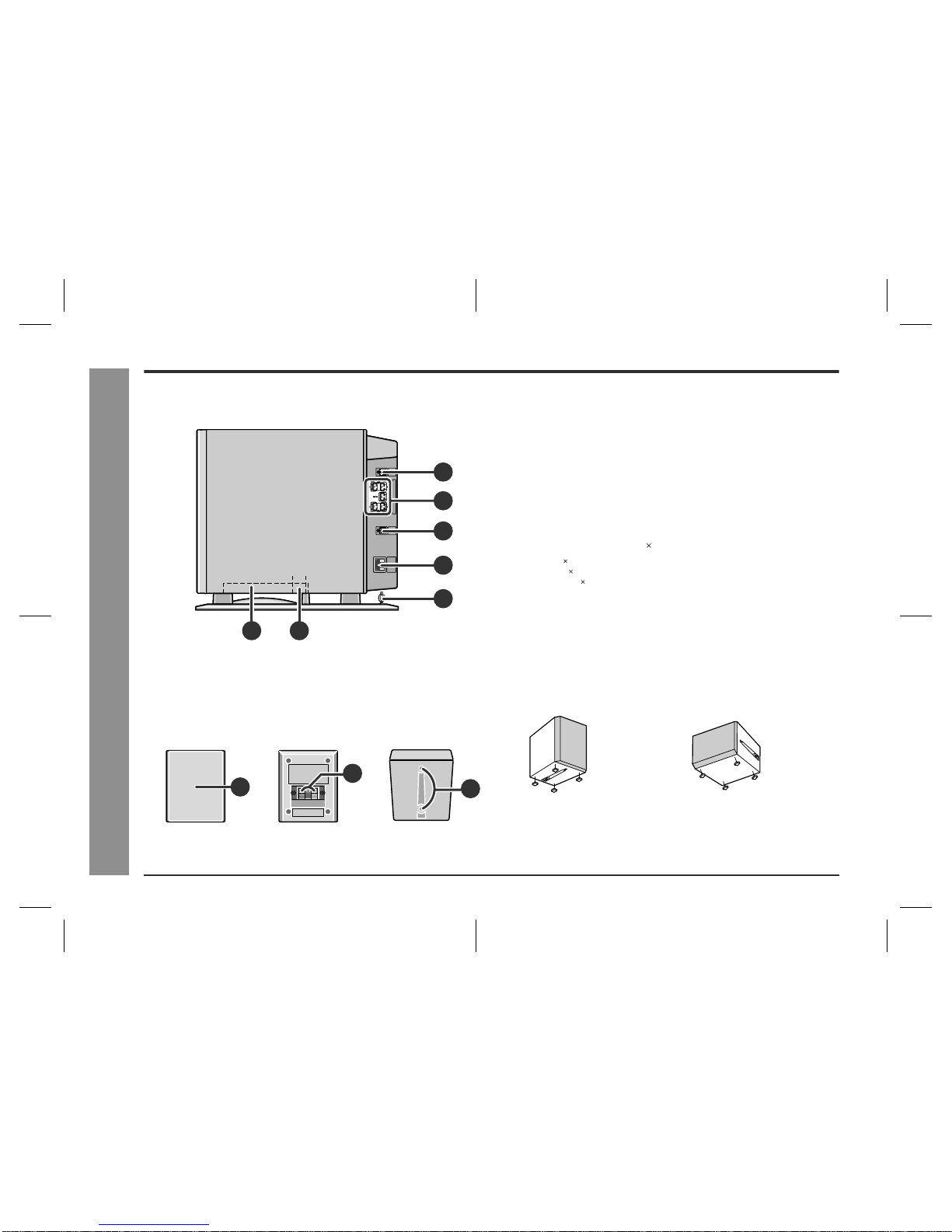
!The SD-AT50W system includes an AV control unit, a subwoofer/amplifier unit,
two front speakers, two surround speakers and a centre speaker.
Special notes
WARNINGS
!When the ON/STAND-BY button is set at STAND-BY position, mains voltage is
still present inside the unit. When the ON/STAND-BY button is set at STAND-BY
position, the unit may be brought into operation by the timer mode or remote con-
trol.
!This unit contains no user serviceable parts. Never remove covers unless qualified
to do so. This unit contains dangerous voltages, always remove mains plug from
the socket before any service operation and when not in use for a long period.
!To prevent fire or shock hazard, do not expose this appliance to dripping or
splashing. No objects filled with liquids, such as vases, should be placed on the
apparatus.
Contents
Page
"General Information
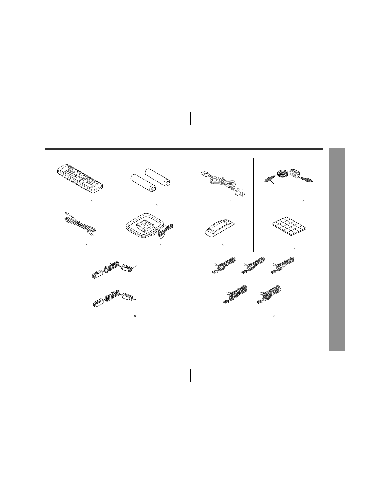
Accessories . . . . . . . . . . . . . . . . . . . . . . . . . . . . . . . . . . . . . . . . . . . . . . . . . . . . . . . 3
Precautions . . . . . . . . . . . . . . . . . . . . . . . . . . . . . . . . . . . . . . . . . . . . . . . . . . . . . . . 4
Controls and indicators . . . . . . . . . . . . . . . . . . . . . . . . . . . . . . . . . . . . . . . . . . 5 - 7
"Preparation for Use
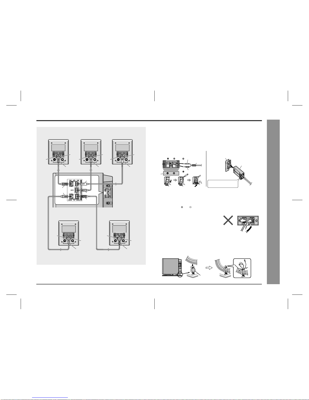
System connections . . . . . . . . . . . . . . . . . . . . . . . . . . . . . . . . . . . . . . . . . . . . . . 8, 9
Aerial connection . . . . . . . . . . . . . . . . . . . . . . . . . . . . . . . . . . . . . . . . . . . . . . . . . 10
Audio connection of other equipment . . . . . . . . . . . . . . . . . . . . . . . . . . . . . 10, 11
Connecting to the AC socket . . . . . . . . . . . . . . . . . . . . . . . . . . . . . . . . . . . . . . . . 12
Headphones . . . . . . . . . . . . . . . . . . . . . . . . . . . . . . . . . . . . . . . . . . . . . . . . . . . . . 12
System installation . . . . . . . . . . . . . . . . . . . . . . . . . . . . . . . . . . . . . . . . . . . . . 12, 13
Remote control . . . . . . . . . . . . . . . . . . . . . . . . . . . . . . . . . . . . . . . . . . . . . . . . . . . 14
General control . . . . . . . . . . . . . . . . . . . . . . . . . . . . . . . . . . . . . . . . . . . . . . . . . . . 14
Setting the clock . . . . . . . . . . . . . . . . . . . . . . . . . . . . . . . . . . . . . . . . . . . . . . . . . . 15
"Basic Operation
Listening to the radio . . . . . . . . . . . . . . . . . . . . . . . . . . . . . . . . . . . . . . . . . . . . . . 16
Listening to the memorised station . . . . . . . . . . . . . . . . . . . . . . . . . . . . . . . . . . 17
Listening to the playback sound from the connected equipment . . . . . . . . . . 18
"Advanced Features
Enjoying surround sound (sound mode) . . . . . . . . . . . . . . . . . . . . . . . . . . 19 - 21
Speaker settings . . . . . . . . . . . . . . . . . . . . . . . . . . . . . . . . . . . . . . . . . . . . . . . 22, 23
Timer and sleep operation . . . . . . . . . . . . . . . . . . . . . . . . . . . . . . . . . . . . . . 24 - 26
Changing the registration in the remote control . . . . . . . . . . . . . . . . . . . . . . . . 27
Operating the connected TV . . . . . . . . . . . . . . . . . . . . . . . . . . . . . . . . . . . . . . . . 28
"References
Error indicators and warnings . . . . . . . . . . . . . . . . . . . . . . . . . . . . . . . . . . . . . . . 28
Troubleshooting chart . . . . . . . . . . . . . . . . . . . . . . . . . . . . . . . . . . . . . . . . . . 29, 30
Maintenance . . . . . . . . . . . . . . . . . . . . . . . . . . . . . . . . . . . . . . . . . . . . . . . . . . . . . 30
Optional accessories . . . . . . . . . . . . . . . . . . . . . . . . . . . . . . . . . . . . . . . . . . . . . . 30
Specifications . . . . . . . . . . . . . . . . . . . . . . . . . . . . . . . . . . . . . . . . . . . . . . . . . . . . 31
Manufactured under license from Digital Theater Systems, Inc. US Pat.
No.5,451,942, 5,956,674, 5,974,380, 5,978,762 and other world-wide patents is-
sued and pending. "DTS" and "DTS Digital Surround" are registered trademarks of
Digital Theater Systems, Inc. Copyright 1996, 2000 Digital Theater Systems, Inc.
All Rights Reserved.
Manufactured under license from Dolby Laboratories. "Dolby", "Pro Logic" and the
double-D symbol are trademarks of Dolby Laboratories. Confidential unpublished
works. 1992-1999 Dolby Laboratories. All rights reserved.

3
SD-AT50W(A)1.fm02/11/8
SD-AT50W
General Information
- Accessories -
Accessories
Please confirm that the following accessories are included.
Note:
Only the above accessories are included.
Remote control 1 "AA" size battery (UM/SUM-3, R6, HP-7
or similar) 2 AC power lead 1 Digital audio cable 1
FM aerial 1 AM loop aerial 1 Stand 1 Antislip speaker cushion sheet
(20 pcs.) 1
System connection cable 2 Speaker connection lead 5
Orange
(For signal/power)
(For sound)
Blue
Black
White
approx. 15 m (45 feet) approx. 15 m (45 feet)
approx. 5 m
(15 feet) approx. 5 m
(15 feet)
approx. 5 m
(15 feet)
Red
Green
Blue Grey

4
SD-AT50W(A)1.fm02/11/8
SD-AT50W
General Information
- Precautions -
Precautions
"General
!Please ensure that the subwoofer/amplifier unit is positioned in a well-ventilated
area and that there is at least 10 cm (4") of free space along the sides and back.
There must also be a minimum of 15 cm (6") of free space on the top of the sub-
woofer/amplifier unit.
!Use the system on a firm, level surface free from vibration.
!Keep the system away from direct sunlight, strong magnetic fields, excessive dust,
humidity and electronic/electrical equipment (home computers, facsimiles, etc.)
which generate electrical noise.
!Do not place anything on top of the components.
!Do not expose the system to moisture, to temperatures higher than 60°C (140°F)
or to extremely low temperatures.
!If the system does not work properly, unplug and plug it in again. Then turn on the
system.
!In case of an electrical storm, unplug the subwoofer/amplifier unit for safety.
!Hold the AC power plug by the head when removing it from the wall socket, as
pulling the lead can damage internal wires.
!Do not remove the outer cover, as this may result in electric shock. Refer
internal service to your local SHARP service facility.
!The ventilation should not be impeded by covering the ventilation openings with
items, such as newspapers, tablecloths, curtains, etc.
!No naked flame sources, such as lighted candles, should be placed on the compo-
nents of the system.
!Attention should be drawn to the environmental aspects of battery disposal.
!This system should only be used within the range of 5°C - 35°C (41°F - 95°F).
Warning:
The voltage used must be the same as that specified by this system. Using this prod-
uct with a higher voltage other than that specified is dangerous and may result in a
fire or other types of accident, causing damage. SHARP will not be held responsible
for any damage resulting from the use of this system with a voltage other than that
specified.
Caution:
!The subwoofer/amplifier unit will get warm whilst being used. Do not touch warm
areas of the subwoofer/amplifier unit for prolonged periods to avoid damage to
you.
!This system is equipped with a special function which protects the amplifier circuit
from damage. When it is activated, the sound switch is turned off. In this case, set
the AV control unit to the stand-by mode and turn it on again.
"Volume control
The sound level at a given volume setting depends on speaker efficiency, location
and various other factors. It is advisable to avoid exposure to high volume levels,
which occur whilst turning the system on with the volume control setting up high, or
whilst continually listening at high volumes.
10 cm (4") 10 cm (4")
15 cm (6")
10 cm (4")
!This subwoofer/amplifier unit is fitted with a cooling
fan at the rear for improved cooling. Do not cover the
opening in this section with any obstacles.
Cooling fan

5
SD-AT50W(A)1.fm02/11/8
SD-AT50W
General Information
- Controls and indicators -
Controls and indicators
"AV control unit
1.Timer Play Indicator
2.Sleep Indicator
3.FM stereo mode indicator
4.FM Stereo Receiving Indicator
5.Audio Signal Indicators/Speaker Indicators
Reference page
6.On/Stand-by Button . . . . . . . . . . . . . . . . . . . . . . . . . . . . . . . . . . 14, 30
7.Timer Set Indicator . . . . . . . . . . . . . . . . . . . . . . . . . . . . . . . . . . . . . . 24
8.Function Button . . . . . . . . . . . . . . . . . . . . . . . . . . . . . . . . . . . . . 16, 18
9.Digital/Analog Input Select or Tuner Band Select Button . . . . 16, 18
10.Volume Up and Down Buttons . . . . . . . . . . . . . . . . . . . . . . . . . . . . . 14
11.Remote Sensor . . . . . . . . . . . . . . . . . . . . . . . . . . . . . . . . . . . . . . . . . 14
12.Power Indicator . . . . . . . . . . . . . . . . . . . . . . . . . . . . . . . . . . . . . . . . . 14
13.Sound Mode Indicators . . . . . . . . . . . . . . . . . . . . . . . . . . . . . . . 20, 21
14.Headphone Socket . . . . . . . . . . . . . . . . . . . . . . . . . . . . . . . . . . . . . . 12
15.Audio Digital Input Socket . . . . . . . . . . . . . . . . . . . . . . . . . . . . . . . . 11
16.Coaxial Digital Audio Input Socket . . . . . . . . . . . . . . . . . . . . . . . . . 10
17.Audio Input Sockets . . . . . . . . . . . . . . . . . . . . . . . . . . . . . . . . . . 10, 11
18.System Connection Sockets (to subwoofer/amplifier unit) . . . . . . 8
19.AM Loop Aerial Terminal . . . . . . . . . . . . . . . . . . . . . . . . . . . . . . . . . 10
20.Aerial Earth Terminal . . . . . . . . . . . . . . . . . . . . . . . . . . . . . . . . . . . . 10
21.FM 75 Ohms Aerial Socket . . . . . . . . . . . . . . . . . . . . . . . . . . . . . . . . 10
Display
Front
Back
The rating label is located
on the bottom of the unit.
This product does not use this terminal.
10
11 13 14
5
(1)
(7) (8)
(2) (3) (4) (5) (6)
(9) (
10
)(
11
)(
12
)(
13
)
15 16 17 19 20 21
12
6789
18
1 2 3 4
(1) Left Front Speaker Indicator (8) Subwoofer Indicator
(2) Front Left Signal Indicator (9) Left Surround Speaker Indicator
(3) Centre Speaker Indicator (10)Surround Left Signal Indicator
(4) Centre Signal Indicator (11)Surround Monaural Signal
Indicator
(5) Front Right Signal Indicator (12)Surround Right Signal Indicator
(6) Right Front Speaker Indicator (13)Right Surround Speaker Indicator
(7) Low Frequency Effect Indicator

6
SD-AT50W(A)1.fm02/11/8
SD-AT50W
General Information
- Controls and indicators -
Controls and indicators (continued)
!Subwoofer/amplifier unit Reference page
1.Subwoofer
2.Bass Reflex Duct
3.System Connection Socket (to AV control unit) . . . . . . . . . . . . . . . .8
4.Speaker Terminals . . . . . . . . . . . . . . . . . . . . . . . . . . . . . . . . . . . . . . . .9
5.System Connection Socket (to AV control unit) . . . . . . . . . . . . . . . .8
6.AC Power Input Socket . . . . . . . . . . . . . . . . . . . . . . . . . . . . . . . . . . .12
7.Lead Holder . . . . . . . . . . . . . . . . . . . . . . . . . . . . . . . . . . . . . . . . . . . . .9
!Satellite speaker 5
Front speaker 2: magnetically shielded
Centre speaker 1: magnetically shielded
Surround speaker 2: magnetically shielded
Reference page
1.Speaker
2.Speaker Terminals . . . . . . . . . . . . . . . . . . . . . . . . . . . . . . . . . . . . . . . .9
3.Mounting Holes for Stand or Bracket (Optionally available) . . . . .13
Using antislip speaker cushions:
You can install satellite speakers either vertically or horizontally.
Affix the cushions (supplied) to the bottom of the speakers to prevent them from slid-
ing or falling due to vibration.
A sheet of speaker cushions (20 pcs.) is supplied with this product. Use 4 cushions
per speaker.
3
4
5
6
7
21
Side
123
Front Back Bottom
(Vertical position) (Horizontal position)

7
SD-AT50W(A)1.fm02/11/8
SD-AT50W
General Information
- Controls and indicators -
!Remote control Reference page
1.Remote Control Transmitter . . . . . . . . . . . . . . . . . . . . . . . . . . . . . . 14
2.Direct Number Buttons . . . . . . . . . . . . . . . . . . . . . . . . . . . . . . . . 17, 27
3.Tuning Up Button . . . . . . . . . . . . . . . . . . . . . . . . . . . . . . . . . . . . . . . 16
4.Tuning Down Button . . . . . . . . . . . . . . . . . . . . . . . . . . . . . . . . . . . . . 16
5.Tuner Preset Down Button . . . . . . . . . . . . . . . . . . . . . . . . . . . . . . . . 17
6.Cursor Button . . . . . . . . . . . . . . . . . . . . . . . . . . . . . . . . . . . . . . . 15, 24
7.Function Buttons . . . . . . . . . . . . . . . . . . . . . . . . . . . . . . . . . . . . . . 16, 18
8.Digital/Analog Input Select or Tuner Band Select Button . . . . . . . 16, 18
9.Sound Mode Select Buttons . . . . . . . . . . . . . . . . . . . . . . . . . . . . . . 21
10.TV On/Stand-by Button . . . . . . . . . . . . . . . . . . . . . . . . . . . . . . . . 27, 28
11.TV Input Select Button . . . . . . . . . . . . . . . . . . . . . . . . . . . . . . . . . . . 28
12.TV Channel Select Buttons . . . . . . . . . . . . . . . . . . . . . . . . . . . . . . . 28
13.On/Stand-by Button . . . . . . . . . . . . . . . . . . . . . . . . . . . . . . . . . . . . . . . 14
14.Display Brightness Select or Clock Display Button . . . . . . . . 14, 15
15.Timer Button . . . . . . . . . . . . . . . . . . . . . . . . . . . . . . . . . . . . . . . . . . . 24
16.Clear Button . . . . . . . . . . . . . . . . . . . . . . . . . . . . . . . . . . . . . . . . . . . . 17
17.Amplifier Initial Setting Button . . . . . . . . . . . . . . . . . . . . . . . . . . . . 22
18.Tuner Preset Up Button . . . . . . . . . . . . . . . . . . . . . . . . . . . . . . . . . . 17
19.Enter Button . . . . . . . . . . . . . . . . . . . . . . . . . . . . . . . . . . 15, 17, 22, 24
20.Return Button . . . . . . . . . . . . . . . . . . . . . . . . . . . . . . . . . . . . . . . . . . 23
21.Dynamic Sound Select Button . . . . . . . . . . . . . . . . . . . . . . . . . . . . . 21
22.TV Volume Up and Down Buttons . . . . . . . . . . . . . . . . . . . . . . . . . . 28
23.Volume Up and Down Buttons . . . . . . . . . . . . . . . . . . . . . . . . . . . . . . 14
3
6
12
15
14
16
18
19
20
21
22
23
17
13
2
5
4
9
8
7
10
11
1
Buttons with " " mark in the illustration can be operated on the remote control only.

8
SD-AT50W(A)1.fm02/11/8
SD-AT50W
Preparation for Use
- System connections -
System connections
!Connecting the components
Connect the AV control unit and subwoofer/amplifier unit as follows.
Caution:
"Make sure to connect the system after unplugging the subwoofer/amplifier unit.
"Put the 2 system connection cables (for sound and signal/power) together. If not,
noises may be heard.
To unplug the system connection cable:
AV control unit
Subwoofer/amplifier unit
System
connection cable
(For sound, black)
Arrow upward
Closer
Closer
Arrow to the left
System
connection cable
(For signal/power,
blue)
FM aerial
AM loop aerial AV control unit
Connecting components Lead
AV control unit
System connection cable
(For sound, black)
System connection cable
(For signal/power, blue)
Subwoofer/
amplifier unit
Subwoofer/
amplifier unit
1
2
Push
Unplug

9
SD-AT50W(A)1.fm02/11/8
SD-AT50W
Preparation for Use
- System connections -
!Connecting the satellite speakers
The speaker terminals on the subwoofer/amplifier unit, the tube and plugs of the
speaker lead, and speaker labels are distinguished by colours.
Connect the speaker and the unit by matching the colours.
Connect the speaker leads to the satellite speakers first and then to the sub-
woofer/amplifier unit.
Caution:
"Make sure to connect the speakers after unplugging the subwoofer/amplifier unit.
"Insert the speaker plug fully with the rising side facing to the left.
"Hold the speaker plug when removing it from the subwoofer/amplifier unit. Pulling
the lead may cause malfunction to the subwoofer/amplifier unit.
"Do not mistake the and , and right and left terminals of the speaker leads. (The
right speaker is placed on the right when you face the system. See page 13.)
"Only the supplied speakers should be used with this product.
"Do not stand or sit on the speakers. You may be injured.
Binding leads:
Tie the leads connected to the subwoofer/amplifier unit with a lead holder.
Red Red Red
Red
Red Red
Red
Grey
Grey
Black Black
Black BlackBlack
Green
Green
Blue
Blue
White
White
Front speaker
(Right)
Surround speaker
(Right) Surround speaker
(Left)
Centre speaker
Subwoofer/
amplifier unit
Front speaker
(Left)
"Never short-circuit the speaker leads. If the
speaker leads are short-circuited, the protec-
tion circuit is activated and the system enters
the stand-by mode. In such a case, check that
the leads are properly connected before turn-
ing the power on again.
Label
Tube
Red
Black
Label
Speaker terminals
(Satellite speaker) (Subwoofer/amplifier unit)
Speaker plug
Plug in with the rising
side facing to the left.
Lead holder

10
SD-AT50W(A)1.fm02/11/8
SD-AT50W
Preparation for Use
- Aerial connection / Audio connection of other equipment -
Aerial connection
Notes:
"Placing the aerial on the system or near the AC power lead may cause noise
pickup. Place the aerial away from the system for better reception.
"When static is still heard even after adjusting the position of the AM loop aerial, try
reversing the wire connections.
Installing the AM loop aerial:
External FM or AM aerial:
Use an external FM or AM aerial if you require better reception. Consult your dealer.
Note:
When using an external AM aerial, be sure to keep the wire of the AM loop aerial
connected.
Audio connection of other
equipment
You can hear the sound of other equipment via this product. Connect the DVD
player, VCR or digital tuner to TV directly to receive the images (refer to the operation
manual of each equipment).
!Connection for the DVD or CD player
sound
You can hear the sound by connecting either the audio cable or digital audio cable.
(The audio cable is not supplied. Purchase a commercially available cable.)
Note:
When the digital audio output socket of the DVD or CD player is optical, connect to
the AUX terminal of this unit regardless of connection type. (Refer to "Connection for
the digital tuner sound" on page 11.)
Supplied FM aerial:
Connect the FM aerial wire to the FM 75 OHMS
socket and position the FM aerial wire in the di-
rection where the strongest signal can be re-
ceived.
Supplied AM loop aerial:
Connect the AM loop aerial wire to the AM and
GND terminals. Position the AM loop aerial for
optimum reception. Place the AM loop aerial on
a shelf, etc., or attach it to a stand or a wall with
screws (not supplied).
< Assembling > < Attaching to the wall >
Wall Screws (not supplied)
White Black
External
FM aerial External
AM aerial
15 m (49 feet )
7.5 m (25 feet )
Earth rod
Earth wire
AM loop aerial
Caution:
Turn off all other equipment before making this connection.
Notes:
"Refer to the operation manual of the equipment to be connected.
"Insert the plugs fully to avoid fuzzy pictures or noise.
DVD player
(CD player)
TV
To coaxial digital
audio input socket
To coaxial digital
audio output socket
To audio
output sockets
To audio
input sockets
Audio cable
(commercially available)
Digital audio cable
(supplied)
Red
White
Red
White

11
SD-AT50W(A)2.fm02/11/8
SD-AT50W
Preparation for Use
- Audio connection of other equipment -
!Connection for the TV sound
Using the audio cable, you can listen to TV sound with this system.
(The audio cable is not supplied. Purchase a commercially available cable.)
!Connection for the VCR sound
Using the audio cable, you can listen to VCR sound with this system.
(The audio cable is not supplied. Purchase a commercially available cable.)
!Connection for the digital tuner sound (or
other optical digital equipment such as an
MD player)
You can hear the sound by connecting either the audio cable or optical digital cable.
(Audio cable and optical digital cable are not included. Please purchase either our
optional cables or commercially available ones.)
If you are using the digital tuner with the optical output socket, you can enjoy better
sound by connecting the tuner to the optical digital input socket of the AV control unit.
Note:
When connecting with an optical digital cable, set the digital output of the digital tuner
to PCM. Refer to the operation manual of the digital tuner.
Audio cable
(commercially available)
Red White
TV
To audio
output sockets
To audio
input sockets
White
Red
TV VCR
To audio
output sockets
To audio
input sockets
Audio cable
(commercially available)
Red
White
Red
White
To optical digital
audio input socket
Digital tuner, etc.
To optical digital audio
output socket
To audio
output sockets
To audio
input sockets
Audio cable
(commercially available)
Optical digital cable
(option: AD-M3DC)
Digital equipment such as
an MD player
TV
Red
White
Red
White

12
SD-AT50W(A)2.fm02/11/8
SD-AT50W
Preparation for Use
- Connecting to the AC socket / Headphones / System installation -
Connecting to the AC socket
!Connecting the AC power lead
Subwoofer/amplifier unit:
After checking all the connections, connect the AC power lead to the AC power input
socket, then to the wall socket.
Notes:
"The power is supplied to the AV control unit by the subwoofer/amplifier unit. The
AV control unit is not equipped with a power lead.
"Never use a power lead other than the one supplied. Otherwise, a malfunction or
an accident may occur.
"Unplug the subwoofer/amplifier unit if it will not be used for prolonged periods of
time.
Headphones
"Before plugging in or unplugging the headphones, reduce the volume.
"Be sure your headphones have a 3.5 mm (1/8") diameter plug and are between 16
ohms and 50 ohms impedance. The recommended impedance is 32 ohms.
"Plugging in the headphones disconnects the speakers automatically. Adjust the
volume using the VOLUME buttons.
"You cannot use the surround feature with headphones.
System installation
!Installing the AV control unit
The AV control unit can be installed either vertically or horizontally.
Use the supplied stand for vertical installation.
(AC INPUT)

13
SD-AT50W(A)2.fm02/11/8
SD-AT50W
Preparation for Use
- System installation -
!Placing the speaker system
The best surround effect will be achieved by placing each speaker at the same dis-
tance from the listening position.
It is recommended to arrange the speakers as shown below.
Identify each speaker by the tube colour.
Notes:
"Place the TV halfway between the front speakers.
"It is recommended that the centre speaker be placed near the television.
"Place the surround speakers at a position just above the height of your ears.
"Set the subwoofer/amplifier unit on a stable, sturdy floor.
"If speakers cannot be placed at equal distances, refer to "Speaker delay setting"
(see page 22).
"The speaker grille is not removable.
The speaker stands and speaker wall brackets are optionally available (see page
30). Refer to their instructions for assembly.
The speakers may be placed beside or near the TV as they are magnetically
shielded. However, colour variation may occur, depending on the type of the TV.
If colour variation occurs...
Turn off the TV (from the power switch).
After 15 - 30 minutes, turn the TV on again.
If the colour variation is still present...
Move the speakers further away from the TV.
Refer to the user's manual of the TV for details.
Caution:
When carrying the subwoofer/amplifier unit, be careful not to touch the subwoofer
located near bottom. Be sure to hold it by the bottom to avoid subwoofer breakage.
Front
speaker (left)
(white)
Subwoofer/
amplifier unit
Front
speaker (right)
(red)
Surround
speaker (left)
(blue)
Surround
speaker (right)
(grey)
Centre
speaker
(green)
Front speaker (left) (white)
Same distance
Front speaker (right) (red)
Centre speaker (green)
Same distance
Subwoofer
Correct

14
SD-AT50W(A)2.fm02/11/8
SD-AT50W
Preparation for Use
- Remote control / General control -
Remote control
!Battery installation
Precautions for battery use:
"Replace all old batteries with new ones at the same time.
"Do not mix old and new batteries.
"Remove the batteries if the system will not be used for long periods of time. This
will prevent potential damage due to battery leakage.
Caution:
"Do not use rechargeable batteries (nickel-cadmium battery, etc.).
"Installing the batteries incorrectly may cause the system to malfunction.
Notes concerning use:
"Replace the batteries if the operating distance is reduced or if the operation
becomes erratic. Purchase 2 "AA" size batteries (UM/SUM-3, R6, HP-7 or similar).
"Periodically clean the transmitter on the remote control and the sensor on the AV
control unit with a soft cloth.
"Exposing the sensor on the AV control unit to strong light may interfere with oper-
ation. Change the lighting or the direction of the AV control unit.
"Keep the remote control away from moisture, heat, shock, and vibrations.
!Test of the remote control
Check the remote control after checking all the connections (see pages 8 - 10 and 12).
Point the remote control directly at the remote sensor on the AV control unit.
The remote control can be used within the range shown below:
Press the ON/STAND-BY button. Does the power turn on? Now, you can enjoy your system.
General control
!To turn the power on
Press the ON/STAND-BY button.
The power indicator lights up.
If the power does not turn on, check if the power leads are plugged in properly.
!Volume control
Press the VOLUME + button to increase the volume and the VOLUME - button for
decreasing.
!To change the display brightness (2 levels)
You can change the brightness of the AV control unit display by holding down the
DISPLAY button on the remote control for 2 seconds or more.
1 Open the battery cover.
2 Insert the batteries according to the direction indicated in the bat-
tery compartment.
When inserting or removing the batteries, push them towardsthe battery terminals.
3 Close the battery cover.
0.2 m - 6 m
(8" - 20')
Remote sensor
AV control unit
Dimmed Brightened
Power indicator
012 39 40
.....

15
SD-AT50W(A)2.fm02/11/8
SD-AT50W
Preparation for Use
- Setting the clock -
Setting the clock
By setting the correct time on the AV control unit, you can use it not only as a clock
but also for timer playback.
In this example, the clock is set for 9:30.
To confirm the time display:
Press the DISPLAY button.
The time display will appear for about 5 seconds.
To readjust the clock:
Perform "Setting the clock" from the beginning.
"In step 1, the time will be displayed. If the clock is cleared, "ADJUST" appears.
"Follow steps 2 - 4.
Note:
You can set the clock even when the system is in the stand-by mode.
Caution:
Unplugging the subwoofer/amplifier unit or a power failure will clear the clock setting.
Perform "Setting the clock" from the beginning.
1Press the DISPLAY button.
2Within 5 seconds, press the ENTER button.
3Press the or button to adjust the
hour and then press the ENTER but-
ton.
Press the or button once to advance the time by 1 hour. Hold it down to ad-
vance continuously.
4Press the or button to adjust the
minutes and then press the ENTER
button.
"Press the or button once to advance the time by 1 minute. Hold it down
to advance continuously.
"The hour will not advance even if minutes advance from "59" to "00".
"The clock starts from "0" second. (Seconds are not displayed.)
"The display returns to normal after approx. 2 seconds.

16
SD-AT50W(A)2.fm02/11/8
SD-AT50W
Basic Operation
- Listening to the radio -
Listening to the radio
To receive an FM stereo transmission:
Press the BAND button to display the "STEREO" indicator.
!"ST" will appear when an FM broadcast is in stereo.
!If the FM reception is weak, press the BAND button to extinguish the "STEREO"
indicator. The reception changes to monaural, and the sound becomes clearer.
After use:
Press the ON/STAND-BY button to enter the power stand-by mode.
Note:
This product can receive FM stereo/FM monaural and AM monaural broadcasts. AM
stereo broadcasts will not be played in stereo.
1Press the ON/STAND-BY button to turn the power on.
2To enter tuner function, display "FM" or "AM" by pressing the
TUNER button.
3Press the BAND button repeatedly to select the desired frequency
band (FM or AM).
4Press the TUNING ( or ) button to tune in to the desired station.
Manual tuning:
Press the TUNING button as many times as required to tune in to the desired
station.
Auto tuning:
When the TUNING button is pressed for more than 0.5 seconds, scanning will
start automatically and the tuner will stop at the first receivable broadcast station.
Notes:
!When radio interference occurs, auto scan tuning may stop automatically at
that point.
!Auto scan tuning will skip weak signal stations.
!To stop the auto tuning, press the TUNING button again.
FM stereo receiving indicator
FM stereo mode indicator

17
SD-AT50W(A)2.fm02/11/8
SD-AT50W
Basic Operation
- Listening to the memorised station -
Listening to the memorised station
"Memorising a station
You can store 40 AM and FM stations in memory and recall them at the push of a
button. (Preset tuning)
Note:
The backup function protects the memorised stations for a few hours should there be
a power failure or the AC power lead disconnection.
"To recall a memorised station
To select a preset station with the direct number buttons:
For example, to choose 28
1 Press the ">10" button.
2 Press the "2" button.
3 Press the "8" button.
Press buttons within 5 seconds.
"To erase all the contents of the preset
memory
1Perform steps 1 - 3 in "Listening to the radio" on page 16.
2Press the ENTER button to enter the preset tuning saving mode.
3Within 5 seconds, press the TUNER
PRESET ( or ) button to select
the preset channel number.
Store the stations in memory, in order, starting with preset channel 1.
4Within 5 seconds, press the ENTER
button to store that station in mem-
ory.
5Repeat steps 1 - 4 to set other stations, or to change a preset sta-
tion.
When a new station is stored in memory, the station previously memorised will
be erased.
Press the TUNER PRESET ( or ) button to select the desired sta-
tion.
Preset channel Frequency and frequency band
Stations 1 - 10: Press the corresponding number ("1" - "10/0").
Stations 11 - 40: Press the ">10" button and then the memorised preset number.
1 Hold the CLEAR button down for 3 seconds
or more.
2 Whilst "CLEAR" is displayed, press the EN-
TER button.

18
SD-AT50W(A)2.fm02/11/8
SD-AT50W
Basic Operation
- Listening to the playback sound from the connected equipment -
Listening to the playback sound from the connected equip-
ment
Example) Listening to a DVD or CD player
Caution:
The system gets warm when used for a long time. It does not mean the system is
damaged.
Note:
A safety feature automatically sets the system to the power stand-by mode if you set
the volume level too high. If this happens, lower the volume level.
1Press the ON/STAND-BY button on the AV control unit or the re-
mote control to turn the power on.
2Turn on the DVD or CD player.
3Press the FUNCTION button to set the
function to "DVD".
!The DVD button on the remote control can also set the function to DVD.
!Press the DIGITAL/ANALOG button to switch the sound to "AUX ANALOG"
or "AUX DIGITAL" depending on the connected input terminal.
!When connecting the DVD or CD player to the AUX socket of this unit, select
"AUX".
4Press the playback button of the DVD or CD player.

19
SD-AT50W(A)2.fm02/11/8
SD-AT50W
Advanced Features
- Enjoying surround sound (sound mode) -
Enjoying surround sound (sound mode)
You can enjoy the surround sound recorded in Dolby Digital or DTS if this system is
digitally connected to a DVD player.
You can also enjoy 2-channel stereo sound in Dolby Pro Logic II.
If (*) is selected, the " " indicator goes out.
(To select the sound mode, see page 21.)
Digital tuner, etc.
DVD player
Stereo signal
Dolby Digital signal
DTS signal
Dolby Pro Logic II
Dolby Digital
DTS
Types of surround Types of input signal Contents Switchable sound
mode
Dolby Digital One of the digital audio systems for theatrical use. You can
enjoy the stereophonic effect in the home theatre system. Stereo
Digital input from discs with this trademark The disc recorded in Dolby Digital is recognised by the sys-
tem automatically when it is played back. Standard
(Dynamic sound)
DTS (Digital Theater Sys-
tems) One of the digital audio systems for theatrical use. As the
sound quality is emphasised, you can enjoy the realistic
sound effect in the home theatre system. The disc recorded
in DTS is recognised by the system automatically when it is
played back.
Stereo
Digital input from discs with this trademark Standard
(Dynamic sound)
Dolby Pro Logic II Inputs from stereo-recorded discs, videotapes, etc. When playing a stereo-recorded disc or videotape, it is recog-
nised by the Dolby Pro Logic II function and the sound is
changed to the 5.1ch digital surround sound automatically.
More natural sound effect can be achieved.
Stereo (*)
Surround (*)
Standard
(Dynamic sound)
Caution:
The surround sound recorded in Dolby Digital or DTS cannot be enjoyed if this system is connected to a DVD player in analogue. The DTS recorded sound especially, cannot
be emitted in analogue. Refer to the operation manual of the DVD player for details.

20
SD-AT50W(A)2.fm02/11/8
SD-AT50W
Advanced Features
- Enjoying surround sound (sound mode) -
Enjoying surround sound (sound mode) (continued)
DOLBY DIGITAL/DTS indicator:
The input signal is recognised automatically and the indicator lights up.
DOLBY PRO LOGIC II indicator:
!This indicator is lit when the 2ch signals are entered to extend them to the 5.1ch
surround sound.
!Even the 2ch sound recorded with Dolby Digital will be extended to the 5.1ch.
Notes:
!When the surround mode is set to the standard or surround mode, the sound of
monaural signals is heard only from the centre speaker.
!When the surround mode is set to stereo, the same monaural sound is reproduced
in both the right and left channels.
!The surround indicator is lit according to the input audio source.
Acoustic effect
Standard
Themaximum of5.1ch surround sound
is reproduced to provide three-dimen-
sional effect. The system automatically
emits the 5.1ch sound according to the
recorded audio signal.
The STANDARD indicator lights up.
Dynamic sound
You can enjoy the normal surround with various scenes.
MOVIE: The bass level is increased for powerful sound effect.
MUSIC: You can enjoy lively sound by producing the articulate sound.
NIGHT: Soft but powerful sound is achieved even at low volumes.
Surround
This mode provides an expansive lis-
tening area by emitting 2-channel
sound.
The SURROUND indicator lights
up.
Stereo
You can enjoy the great acoustic ef-
fects of the front speakers and sub-
woofer.
The STEREO indicator lights up.
1 Front Left Signal Indicator
2 Centre Signal Indicator
3 Front Right Signal Indicator
4 LFE (Low Frequency Effect) Signal Indicator
5 Surround Left Signal Indicator
6 Surround Monaural Signal Indicator
7 Surround Right Signal Indicator
2
1 3
4
57
6
Table of contents
Other Sharp Home Theater System manuals

Sharp
Sharp SD-AS10H User manual

Sharp
Sharp HT-CN400DVH User manual

Sharp
Sharp SD-AT1000W User manual

Sharp
Sharp CD-DVD500 User manual

Sharp
Sharp HT-X1H User manual

Sharp
Sharp HT-SB600 User manual

Sharp
Sharp SD-AT1000 User manual

Sharp
Sharp HT-SL50 User manual

Sharp
Sharp SD-AT1000 User manual

Sharp
Sharp HT-CN400DVH User manual

Sharp
Sharp HT-DD5000 User manual

Sharp
Sharp HT-DP2500W User manual

Sharp
Sharp HT-SBW800 User manual

Sharp
Sharp AQUOS BD-MPC41U User manual

Sharp
Sharp HT-SB60 User manual

Sharp
Sharp HT-CN410DVH User manual

Sharp
Sharp HT-CN400DVW User manual

Sharp
Sharp HT-SB602 User manual

Sharp
Sharp HT-M700H User manual

Sharp
Sharp HT-SB40 User manual