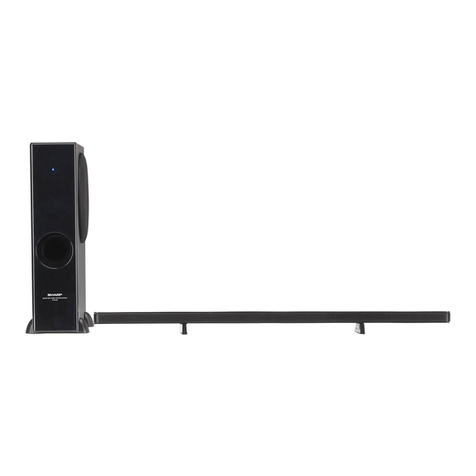
Sharp Aquos AN-ACS1U User manual

Printed in Malaysia
Impreso en Malasia
TINSEA141WJQZ
08P02-MA-NM
SHARP ELECTRONICS CORPORATION
Sharp Plaza, Mahwah, New Jersey 07430-2135
SHARP CORPORATION
ENGLISH ESPAÑOL
IMPORTANT : Please read this operation manual before starting operating the equipment.
IMPORTANTE : Lea este manual de operación antes de comenzar a operar el equipo.
AN-ACS1U
1BIT THEATER RACK SYSTEM
OPERATION MANUAL
MANUAL DE OPERACIÓN
AN-ACS1Ucover1-4.indd2-3AN-ACS1Ucover1-4.indd2-3 2008/01/0718:08:302008/01/0718:08:30

AN-ACS1Ucover1-4.indd4-5AN-ACS1Ucover1-4.indd4-5 2008/01/0718:08:312008/01/0718:08:31

1
General Information
n
Contents
nGeneral Information
IMPORTANT INFORMATION........................... 1
DEAR SHARP CUSTOMER ............................. 2
IMPORTANT SAFETY INSTRUCTIONS
............ 2 - 4
Precautions ...................................................... 5
Accessories ..................................................... 6
Trademarks ...................................................... 6
Controls and indicators ...........................7 - 10
oPreparation for Use
Installing the unit .................................... 11 - 12
Connections............................................ 13 - 15
AC power connection ................................... 16
Remote control .............................................. 17
General control .............................................. 18
pBasic Operation
Listening to the playback sound.................. 19
Enjoying surround sound (sound mode)
..... 20 - 23
AQUOS LINK ........................................... 24 - 27
qReferences
Troubleshooting chart................................... 28
Error indications and warnings.................... 29
Reset procedure ............................................ 29
Specifications ................................................ 30
Maintenance .................................................. 30
CONSUMER LIMITED WARRANTY.............. 31
• The illustrations and on-screen displays in this operation
manual are for explanation purposes and may vary slightly
from the actual operations.
ENGLISH
CAUTION:
TO REDUCE THE RISK OF ELECTRIC SHOCK, DO NOT
REMOVE COVER. NO USER-SERVICEABLE PARTS
INSIDE. REFER SERVICING TO QUALIFIED SERVICE
PERSONNEL.
INFORMATION
This equipment has been tested and found to comply with the limits for a Class B digital device, pursuant to Part 15 of the FCC
Rules. These limits are designed to provide reasonable protection against harmful interference in a residential installation. This
equipment generates, uses and can radiate radio frequency energy and, if not installed and used in accordance with the instruc-
tions, may cause harmful interference to radio communications. However, there is no guarantee that interference will not occur in a
particular installation. If this equipment does cause harmful interference to radio or television reception, which can be determined by
turning the equipment off and on, the user is encouraged to try to correct the interference by one or more of the following measures:
—Reorient or relocate the receiving antenna.
—Increase the separation between the equipment and receiver.
—Connect the equipment into an outlet on a circuit different from that to which the receiver is connected.
—Consult the dealer or an experienced radio/TV technician for help.
The lightning flash with arrowhead symbol,
within an equilateral triangle, is intended to
alert the user to the presence of uninsulated
“dangerous voltage” within the product’s
enclosure that may be of sufficient magnitude
to constitute a risk of electric shock to persons.
The exclamation point within an equilateral
triangle is intended to alert the user to the
presence of important operating and
maintenance (servicing) instructions in the
literature accompanying the appliance.
IMPORTANT INFORMATION
AN-ACS1Uen.indb1AN-ACS1Uen.indb1 2008/01/0718:06:282008/01/0718:06:28

2
Electricity is used to perform many useful functions, but it can also cause personal injuries and property damage if
improperly handled. This product has been engineered and manufactured with the highest priority on safety. However,
improper use can result in electric shock and/or fire. In order to prevent potential danger, please observe the following
instructions when installing, operating and cleaning the product. To ensure your safety and prolong the service life of
your 1 BIT THEATER RACK SYSTEM, please read the following precautions carefully before using the product.
1) Read these instructions.
2) Keep these instructions.
3) Heed all warnings.
4) Follow all instructions.
5) Do not use this apparatus near water.
6) Clean only with dry cloth.
7) Do not block any ventilation openings. Install in accordance with the manufacturer's instructions.
8) Do not install near any heat sources such as radiators, heat registers, stoves, or other apparatus (including
amplifiers) that produce heat.
9) Do not defeat the safety purpose of the polarized or grounding-type plug. A polarized plug has two blades with
one wider than the other. A grounding type plug has two blades and a third grounding prong. The wide blade or
the third prong are provided for your safety. If the provided plug does not fit into your outlet, consult an
electrician for replacement of the obsolete outlet.
10) Protect the power cord from being walked on or pinched particularly at plugs, convenience receptacles, and the
point where they exit from the apparatus.
11) Only use attachments/accessories specified by the manufacturer.
12) Use only with the cart, stand, tripod, bracket, or table specified by the manufacturer, or sold with the
apparatus. When a cart is used, use caution when moving the cart/apparatus combination to avoid
injury from tip-over.
13) Unplug this apparatus during lightning storms or when unused for long periods of time.
14) Refer all servicing to qualified service personnel. Servicing is required when the apparatus has been damaged in
any way, such as power-supply cord or plug is damaged, liquid has been spilled or objects have fallen into the
apparatus, the apparatus has been exposed to rain or moisture, does not operate normally, or has been
dropped.
Additional Safety Information
15) Power Sources—This product should be operated only from the type of power source indicated on the marking
label. If you are not sure of the type of power supply to your home, consult your product dealer or local power
company. For products intended to operate from battery power, or other sources, refer to the operating
instructions.
16) Overloading—Do not overload wall outlets, extension cords, or integral convenience receptacles as this can
result in a risk of fire or electric shock.
17) Object and Liquid Entry—Never push objects of any kind into this product through openings as they may touch
dangerous voltage points or short-out parts that could result in a fire or electric shock. Never spill liquid of any
kind on the product.
18) Damage Requiring Service—Unplug this product from the wall outlet and refer servicing to qualified service
personnel under the following conditions:
a) When the AC cord or plug is damaged,
b) If liquid has been spilled, or objects have fallen into the product,
c) If the product has been exposed to rain or water,
d) If the product does not operate normally by following the operating instructions.
Adjust only those controls that are covered by the operating instructions as an improper adjustment of other
controls may result in damage and will often require extensive work by a qualified technician to restore the
product to its normal operation,
e) If the product has been dropped or damaged in any way, and
f) When the product exhibits a distinct change in performance - this indicates a need for service.
19) Replacement Parts—When replacement parts are required, be sure the service technician has used replacement
parts specified by the manufacturer or have the same characteristics as the original part. Unauthorized
substitutions may result in fire, electric shock, or other hazards.
20) Safety Check—Upon completion of any service or repairs to this product, ask the service technician to perform
safety checks to determine that the product is in proper operating condition.
21) Wall or ceiling mounting—When mounting the product on a wall or ceiling, be sure to install the product
according to the method recommended by the manufacturer.
22) The mains plug is used as disconnect device and shall always remain readily operable.
DEAR SHARP CUSTOMER
Thank you for your purchase of the Sharp 1 BIT THEATER RACK SYSTEM. To ensure
safety and many years of trouble-free operation of your product, please read the
Important Safety Instructions carefully before using this product.
IMPORTANT SAFETY INSTRUCTIONS
AN-ACS1Uen.indb2AN-ACS1Uen.indb2 2008/01/0718:06:292008/01/0718:06:29

3
General Information
n
• Water and Moisture — Do not use this product near water - for example, near a bath tub, wash bowl,
kitchen sink, or laundry tub; in a wet basement; or near a swimming pool; and the like.
• Do not put the product on an unstable place. If you put the product on an uneven or unstable place, it may
fall down and you may be injured. Put the product on a flat surface strong enough to take the weight.
• Ventilation — The vents and other openings in the cabinet are designed for ventilation. Do not cover or
block these vents and openings since insufficient ventilation can cause overheating and/or shorten the life of
the product.
• Heat — The product should be situated away from heat sources such as radiators, heat registers, stoves,
or other products that produce heat.
• Lightning — For added protection for this product during a lightning storm, or when it is left unattended
and unused for long periods of time, unplug it from the wall outlet and disconnect the antenna. This will
prevent damage to the equipment due to lightning and power-line surges.
• Selecting the location — Select a place with no direct sunlight and good ventilation.
• To prevent fire, never place any type of candle or flames on the top or near the product.
• To prevent fire or shock hazard, do not expose this product to dripping or splashing.
No objects filled with liquids, such as vases, should be placed on the product.
IMPORTANT SAFETY INSTRUCTIONS
AN-ACS1Uen.indb3AN-ACS1Uen.indb3 2008/01/0718:06:292008/01/0718:06:29

4
• To prevent fire or shock hazard, do not place the AC cord under the product or other heavy
items.
• Turn off the main power and unplug the AC cord from the wall outlet before handling.
• To clean the outer cabinet, periodically wipe it with a soft cloth.
• Do not use chemicals for cleaning. It may damage the cabinet finish.
• Precautions when transporting this product — Be sure to always carry this product by two people holding
it with two hands — one hand on each side of the this product.
IMPORTANT SAFETY INSTRUCTIONS
AN-ACS1Uen.indb4AN-ACS1Uen.indb4 2008/01/0718:06:302008/01/0718:06:30

5
General Information
n
■ General
• Please ensure that the equipment is positioned in a
well-ventilated area and that there is at least 4" (10 cm) of free
space along the sides and back. There must also be a minimum
of 4" (10 cm) of free space on the top of the unit.
• Keep the unit away from direct sunlight, strong magnetic fields,
excessive dust, humidity and electronic/ electrical equipment
(home computers, facsimiles, etc.) which generate electrical
noise.
• Do not expose the unit to moisture, to temperatures higher than
140°F (60°C) or to extremely low temperatures.
• If the unit does not work properly, unplug and plug it in again.
Then turn on the unit.
• In case of an electrical storm, unplug the unit for safety.
• Hold the AC power plug by the head when removing it from the
AC outlet, as pulling the cord can damage internal wires.
• Do not remove the outer cover, as this may result in electric
shock. Refer internal service to your local SHARP service
facility.
• This unit should only be used within the range of 41°F - 95°F
(5°C - 35°C).
• The ventilation should not be impeded by covering the
ventilation openings with items, such as newspapers,
tablecloths, curtains, etc.
• The apparatus is designed for use in moderate climate.
• Attention should be drawn to the environmental aspects of
battery disposal.
• The glass parts of this product are made of reinforced glass,
but dropping pointed objects on them or strongly hitting a glass
surface may cause it to break. Always take proper precautions.
Warning:
• The voltage used must be the same as that specified by this unit.
Using this product with a higher voltage other than that specified
is dangerous and may result in a fire or other types of accident,
causing damage. SHARP will not be held responsible for any
damage resulting from the use of this unit with a voltage other than
that specified.
Precautions
■ Cooling fan
This unit is fitted with a cooling fan at the rear for improved cooling.
Do not cover the opening in this section with any obstacles.
Cooling fan
Rear view
Caution:
• The unit will get warm while being used. Do not touch the warm
areas of the unit for prolonged periods to avoid damage to you.
• This unit is equipped with a special function which protects the
amplifier circuit from damages. When it is activated, the sound
switch is turned off. In this case, set the unit to the stand-by mode
and turn on again.
■ Volume control
The sound level at a given volume setting depends on speaker
efficiency, location and various other factors. It is advisable to avoid
exposure to high volume levels, which occurs while turning the
unit on with the volume control setting up high, or while continually
listening at high volumes.
AN-ACS1Uen.indb5AN-ACS1Uen.indb5 2008/01/0718:06:302008/01/0718:06:30

6
Remote control (x1)
Page 10
“AA” size battery (x2) HDMI cable (x1)
Please confirm that the following accessories are included.
Accessories
Page 17 Pages 14-15
Pages 14-15 Page 11 Page 11
Page 11 Page 30 Page 12
Optical digital cable (x1) Top glass cover (x1) Glass shelf (x1)
Wall spacer (x2) Cloth (x1) Cable clamp (x5)
(UM/SUM-3, R6, HP-7 or similar)
Operation manual (×1)
NOTE
• Only the above accessories are included.
• The top glass cover, glass shelf, wall spacers and other parts must be installed before use. (Pages 11-12)
Trademarks
•“HDMI”, the HDMI logo and High-Definition Multimedia Interface are trademark or registered trademarks of HDMI Licensing
LLC.
•Manufactured under license from Dolby Laboratories. “Dolby”, “Pro Logic”, the double-D symbol, Audistry and the sound
shell logo are trademarks of Dolby Laboratories.
•“DTS” and “DTS Digital Surround” are registered trademarks of DTS, Inc.
AN-ACS1Uen.indb6AN-ACS1Uen.indb6 2008/01/0718:06:302008/01/0718:06:30

7
General Information
n
Controls and indicators
Front speaker (L-ch)
• The left-channel sound is
reproduced here.
Front speaker (R-ch)
• The right-channel sound is reproduced here.
Subwoofer
Control/Display part
Top glass cover
Glass shelf
• The low-frequency sound
is reproduced here.
Page 11
Page 11
The top glass cover and glass shelf must be installed before use. (Page 11)
Caution:
• The subwoofer is delicate and should be handled with care.
Main unit (front view)
Handling precautions for the main unit and speakers
Moving or installing the product should be performed by at least two people.
Caution:
• When moving or installing the unit, do not hold it by the speaker mesh. Otherwise the speakers may be damaged.
Grasp the unit at the areas on the underside of the top board, marked by arrows in the illustration shown above.
• Do not carry the unit by holding the metal frame that supports the glass shelf.
AN-ACS1Uen.indb7AN-ACS1Uen.indb7 2008/01/0718:06:312008/01/0718:06:31

8
Controls and indicators
Control part
Remote sensor
• Point the remote control at
this sensor.
Power indicator
• Lit in green: unit is operating
• Lit in red: unit is in stand-by mode
POWER
• Switches the unit between on and off (stand-by).
INPUT
• Press this button to select the input source. Each
push of the button cycles through the following
settings.
VOLUME +/-
• Turns up/down the volume.
HDMI1 (INPUT) HDMI2 (INPUT)
AUX1
AUX2
AUX4
AUX3
AUDIO INPUT
(ANALOG)
DIGITAL
AUDIO INPUT
(OPTICAL)
Display top row (Input source)
• Shows the currently selected input source.
Display bottom row (Volume/sound mode)
• Shows information about sound mode, volume level, Dolby Virtual
Speaker, Audistry, and other settings.
• Shows the input signal type.
• Lights up when Dolby ProLogic II is active.
• Lights up when Dolby Virtual Speaker mode
is active.
• Lights up when Audistry mode is active.
,,
Page 16
Page 17
Page 19
Page 23
Page 22
Page 20
Page 20
Page 19
Pages 16•19
Pages 18-23
Page 18
Depending on the input signal type and selected settings, one or
more of the following indicators lights up.
……SOUND SPACE
……NATURAL BASS
……INTELLIGENT VOLUME
……MONO TO STEREO
Display part
Various information about the operating condition of the unit is shown here, including the input source, volume level setting,
sound mode, subwoofer level setting, mute, etc.
AN-ACS1Uen.indb8AN-ACS1Uen.indb8 2008/01/0718:06:322008/01/0718:06:32

9
General Information
n
Controls and indicators
Main unit (rear view)
Wall spacer Amplifier part
Subwoofer
Wall spacer Page 11Page 11
Bass reflex duct (Do not insert any objects here.)
Amplifier part
Cooling fan
• The unit has a built-in fan for improved
cooling. The fan starts up automatically
when power is turned on. Do not block
or cover the fan openings.
AUDIO INPUT
AUX3, AUX4 connectors
• Connect a TV, CD player, cassette deck or other
component with analog audio output (line output)
here.
HDMI INPUT/OUTPUT
HDMI INPUT (FROM PLAYER)
HDMI1, HDMI 2 connectors
• Connect a player or other component with HDMI output
here.
HDMI OUTPUT (TO TV)
• Connect a TV with HDMI input here.
DIGITAL AUDIO INPUT (OPTICAL)
AUX1, AUX2 connectors
• Connect a TV or other component with digital audio output
(optical) here.
Pages 14•15
Pages 14•15 Pages 14•15
AN-ACS1Uen.indb9AN-ACS1Uen.indb9 2008/01/0718:06:322008/01/0718:06:32

10
Controls and indicators
Remote control
POWER
Remote control transmitter
• Press to turn the power of the unit on
and off (stand-by).
2 5・3 9 ページ
VOLUME +/-
• Press to adjust the volume.
MUTE
• Press to temporarily mute the sound.
SOUND MODE
• Press one of these buttons to select the
sound mode.
TONE
• Press to adjust the tonal quality.
MENU
• Press to display the menu.
DOLBY VIRTUAL
SPEAKER
• Press to turn the Dolby Virtual Speaker
function on and off.
INPUT
• Press one of these buttons to select the
input source.
ENTER
• Press to set a menu or an item.
Audistry sound mode
• Press one of these buttons to select an
Audistry mode.
Cursor
• Press to select menus and items.
SUBWOOFER LEVEL (+/-)
• Press to adjust the Subwoofer level.
Page 16
Page 21
Page 18
Page 18
Page 23
Page 22
Page 18
Page 19
Pages 25-27
Pages 25-27
Pages 18•19
Page 27
AN-ACS1Uen.indb10AN-ACS1Uen.indb10 2008/01/0718:06:332008/01/0718:06:33

11
Preparation for Use
o
Installing the unit
Before installation
• Because this unit is extremely heavy, it must always be handled by at least
two persons, to prevent the risk of injury and accidents.
• For safety, protective gloves should be worn when handling the unit.
• For information on supplied parts and accessories, please see page 6.
• Take care not to scratch the floor etc. when moving the unit.
• Do not touch the speaker mesh on the front side when moving the unit.
Otherwise the mesh or the speakers may be damaged.
• Never place the unit on an unstable surface or any surface unable to sustain
its weight. Otherwise the unit may fall over or drop, and there is a risk of
damage and injury.
• Before moving the unit, be sure to turn power off and disconnect the power
cord from the AC outlet. Also disconnect all cables from other components.
Double-check this before you begin. Otherwise there is a risk of damage and
injury.
• Do not move the unit with a TV or other component on top. Otherwise such a
component may fall over or drop, and there is a risk of damage and injury.
• The glass parts are made of reinforced glass, but dropping pointed objects
on them or strongly hitting a glass surface may cause it to break. Always take
proper precautions.
Placing the top glass cover and glass shelf on the unit
Caution:
•
This procedure should be performed by at least two people.
•
The top glass cover and glass shelf are not fastened to the
unit.
•
After placing the top glass cover and glass shelf on the
unit, take care to keep the unit level when transporting it.
Otherwise these parts may fall off, and there is a risk of
damage and injury.
Attaching the wall spacers
The wall spacers can be attached to the rear side of the top section of the unit (two locations, right and left).
• The wall spacers serve to ensure proper clearance behind the unit and protect the connection cables from damage.
Caution:
•
Do not carry the unit by holding the wall spacers.
•
When moving the unit, grasp it at the areas marked by arrows
on the underside of the top board.
•
Do not carry the unit by holding the metal frame that supports
the glass shelf.
Speaker mesh sectionsSpeaker mesh sections
Position the top glass
cover and glass shelf
correctly as shown here.
Glass shelf cushion pads
(already attached to the unit)
Top glass cover
cushion pads
(already attached
to the unit)
Logo sticker
Top glass cover
Glass shelf
Precaution label
Position the top glass
cover and glass shelf
correctly as shown here.
Glass shelf cushion pads
(already attached to the unit)
Top glass cover
cushion pads
(already attached
to the unit)
Logo sticker
Top glass cover
Glass shelf
Precaution label
Insert wall
spacer here
(2 locations)
Wall spacer
(supplied)
Wall spacer
(supplied)
Rear view
Insert wall
spacer here
(2 locations)
Wall spacer
(supplied)
Wall spacer
(supplied)
Rear view
AN-ACS1Uen.indb11AN-ACS1Uen.indb11 2008/01/0718:06:332008/01/0718:06:33

12
Positioning the unit in the room
Choose the installation location of the unit so that
there is enough room to position the TV, media player,
or other components and to make the necessary
connections.
Caution:
•
Installation should be performed by at least two people.
When moving the unit, take care to keep it level. Otherwise
the top glass cover or glass shelf may fall off, and there is a
risk of damage and injury.
Installing a TV, media player, or similar
Place the TV in the center of the unit.
Top glass cover load carrying capacity : approx. 80 kg (176 lbs.)
Glass shelf load carrying capacity : approx. 25 kg (55 lbs.)
Cable clamps
Cables connected to the amplifier section on the rear of the unit can be neatly organized with the supplied cable clamps. Use
these as required.
(1) Attach cable clamp to the unit (2) Fasten cable(s)
Peel off cover
and stick to
the unit
Cable(s)
Adhesive
face
Ensure that there is a
clearance of at least
10 cm (4 in.) to the
rear wall.
Ensure that there is a
clearance of at least
10 cm (4 in.) to the
rear wall.
Installing the unit
AN-ACS1Uen.indb12AN-ACS1Uen.indb12 2008/01/0718:06:332008/01/0718:06:33

13
Preparation for Use
o
Connections
• Before making connections, disconnect the power cords from all units.
Refer to the manual of the respective unit for detailed instructions.
• Do not connect HDMI CEC-enabled audio equipment to this unit or to the TV.
Otherwise the AQUOS LINK function will not operate correctly.
■The audio and video signal flow in a system using this unit is shown below.
Signal flow when using equipment with HDMI connectors AQUOS LINK
Video signal
Audio signal
Optical digital cable TV
Blu-ray Disc player or similar
HDMI cable
HDMI cable
AQUOS AUDIO system
NOTE
• We recommend to connect a component with HDMI output to the HDMI input of the AQUOS AUDIO system. If the component is connected
directly to the TV, the sound of the HDMI component sometimes cannot not be reproduced by the AQUOS AUDIO system.
• If the input selector of the AQUOS AUDIO system is not set to HDMI 1 or HDMI 2, the sound from the Blu-ray Disc player or similar
component cannot be reproduced by the TV.
AQUOS LINK function
When connecting an HDMI CEC (Consumer Electronics Control)-enabled AQUOS TV, Blu-ray Disc player, or similar
component, operation of these components in the system can be linked.
(For details on how to use AQUOS LINK function, please see pages 24 - 27.)
Signal flow when using equipment without HDMI connectors
Video signal
Audio signal
DVD player/VCR or similar
AQUOS AUDIO system TV
Optical digital cable
or Audio cable
AV cable
Optical digital cable
or Audio cable
NOTE
• Use only audio cables without integrated resistors. Otherwise the volume level will be reduced.
For details on
connection, please
see pages 14 - 15.
AN-ACS1Uen.indb13AN-ACS1Uen.indb13 2008/01/0718:06:332008/01/0718:06:33

14
Connecting a TV (with HDMI connector) AQUOS LINK
Use both the optical digital cable and HDMI cable for the connection.
To use the AQUOS LINK function (pages 24 - 27), connect the audio signal of the TV to the AUX1 connector. If AUX2 is used,
you must manually select the AUX2 input.
Rear panel
(amplifier part)
To HDMI OUTPUT
(TO TV) connector
HDMI cable
To HDMI input connector
To DIGITAL AUDIO
INPUT (OPTICAL)
connector (AUX1)
To DIGITAL AUDIO
output (optical) connector
Optical
digital cable
HDMI
Insert cable until you hear a click.
TV
AUDIO
DIGITAL
Connect both
cables
Cables to use
Optical digital cable (supplied)
HDMI cable (supplied)
If the cable is equipped with a protective
cap, remove it before making the
connection.
NOTE
• If only the HDMI cable is used for the
connection, the sound of the TV cannot
be reproduced by the AQUOS AUDIO
system. To reproduce the sound of the
TV with the AQUOS AUDIO system, the
optical digital cable must be connected.
• When connecting an HDMI CEC-enabled
AQUOS TV or similar component, the
AQUOS LINK function can be used.
(Pages 24 - 27)
Connecting a TV (without HDMI connector)
Use the optical digital cable for the connection.
If the TV does not have a digital audio output, use regular audio cable to make an analog connection.
Insert cable until you hear a click.
TV
Rear panel
(amplifier part)
To AUDIO output jacks
or
To DIGITAL AUDIO INPUT
(OPTICAL) connector
(AUX1 or AUX2)
To DIGITAL AUDIO
output (optical) connector
To AUDIO INPUT
connectors
(AUX3 or AUX4)
Audio cable
AUDIO
L
R
Optical
digital cable
AUDIO
DIGITAL
Make one of these
connections (not both)
Cables to use
Optical digital cable
(supplied or commercially available)
Audio cable (commercially available)
If the cable is equipped with a protective
cap, remove it before making the
connection.
Connections
Left (white)
Right (red)
Left (white)
Right (red)
AN-ACS1Uen.indb14AN-ACS1Uen.indb14 2008/01/0718:06:342008/01/0718:06:34

15
Preparation for Use
o
Connections
Connecting a Blu-ray Disc player or similar (with HDMI connector)
AQUOS LINK
Use the HDMI cable for the connection.
To HDMI OUTPUT
(TO TV) connector
To HDMI input
connector of TV
To HDMI INPUT
(FROM PLAYER) connector
(HDMI 1 or HDMI 2)
To DIGITAL AUDIO INPUT (OPTICAL)
connector (AUX1)
To DIGITAL AUDIO output
(optical) connector of TV
A single cable carries
both video and audio
information.
Rear panel
(amplifier part)
Blu-ray Disc player
or similar
To HDMI output
connector
To HDMI output
connector
Blu-ray Disc player
or similar
Insert cable until you hear a click.
Cables to use
HDMI cable
(supplied or commercially available)
If the cable is equipped with a protective
cap, remove it before making the
connection.
NOTE
• When connecting an HDMI CEC-enabled
AQUOS TV, Blu-ray Disc player, or similar
component, the AQUOS LINK function
can be used. (Pages 24 - 27)
• When using a commercially available HDMI
cable, it is recommended to limit cable
length to 3 m (10 ft.), to ensure stable
operation and to prevent image quality
degradation.
Connecting a DVD player, VCR, or similar (without HDMI connector)
Use optical digital cable or audio cable for the connection.
Optical
digital cable
Rear panel
(amplifier part)
To AUDIO output jacks
or
L
R
To DIGITAL AUDIO
INPUT (OPTICAL)
connector (AUX1 or AUX2)
To DIGITAL AUDIO
output (optical) connector
To AUDIO INPUT
connectors
(AUX3 or AUX4)
Insert cable until you hear a click.
Make one of
these connections
(not both)
DVD player/VCR or similar
To the TV (video)
Audio cable
AUDIO
DIGITAL
AUDIO
Cables to use
Optical digital cable
(supplied or commercially available)
Audio cable (commercially available)
If the cable is equipped with a protective
cap, remove it before making the
connection.
NOTE
• Connect the video output of the DVD
player or VCR directly to the TV, using
suitable A/V cable.
Left (white)
Right (red)
Left (white)
Right (red)
AN-ACS1Uen.indb15AN-ACS1Uen.indb15 2008/01/0718:06:342008/01/0718:06:34

16
AC power connection
Connecting the AC power cord
After checking that all the connections have been made correctly, connect the AC power cord to the AC outlet.
AC120V
60Hz
To AC outlet
Rear panel (amplifier part)
Power indicator
lights up in red.
Lit in red
NOTE
• When connecting the power cords of the various components, plug in the
power cord of the TV last.
• If you have connected or disconnected an HDMI cable or have changed
connections, cycle power to the TV (turn it off and then again) while power to all
other components is on.
• Never use a power cord other than the one supplied. Otherwise, a malfunction
or an accident may occur.
• Unplug the AC power cord from the AC outlet if the unit will not be in use for a
prolonged period of time.
• Always turn power off before disconnecting a power cord. Always grasp the
plug and do not pull on the cable, as this can lead to cable break.
To turn the power on
To turn the power on:
Press POWER on the remote control or the main unit.
• The power indicator lights up green.
• If the power does not turn on, check whether the power
cord is plugged in properly.
To set the unit to the stand-by mode:
Press POWER again.
• The power indicator lights up red.
NOTE
• After power-on, there is a mute interval of 8 seconds.
• After the unit enters the stand-by mode, wait a few seconds to turn on again.
Lit in greenLit in green
Lit in redLit in red
AN-ACS1Uen.indb16AN-ACS1Uen.indb16 2008/01/0718:06:352008/01/0718:06:35

17
Preparation for Use
o
Remote control
Battery installation
1Open the battery cover.
Open
2Insert the batteries according to the direction
indicated in the battery compartment.
Insert battery with
side first
3Close the cover.
Close
Precautions for battery use:
• Replace all old batteries with new ones at the same time.
• Do not mix old and new batteries.
• Remove the batteries if the unit will not be used for long periods of
time. This will prevent potential damage due to battery leakage.
Caution:
•
Do not use rechargeable batteries (nickel-cadmium battery, etc.).
•
Installing the batteries incorrectly may cause the unit to malfunction.
Test of the remote control
Point the remote control directly at the remote sensor on the
main unit.
The remote control can be used within the range shown left.
NOTE
• If the power does not come on, check whether the power cord is
properly plugged in and whether the batteries have been inserted
correctly into the remote control.
• Replace the batteries if the operating distance is reduced or if the
operation becomes erratic.
Purchase 2 “AA” size batteries (UM/SUM-3, R6, HP-7 or similar).
• Periodically clean the transmitter on the remote control and the
sensor on the unit with a soft cloth.
• Exposing the sensor on the unit to strong light may interfere with
operation. Change the lighting or the direction of the unit.
• Keep the remote control away from moisture, heat, shock, and
vibrations.
Approx.
15º
Approx.
20cm (8 in.)
to 6m (20 ft.)
Remote sensor
Approx.
15º
AN-ACS1Uen.indb17AN-ACS1Uen.indb17 2008/01/0718:06:352008/01/0718:06:35

18
General control
Volume control
Main unit operation:
Press VOLUME + to increase the volume and VOLUME - for
decreasing.
Remote control operation:
Press VOLUME + to increase the volume and VOLUME - for
decreasing.
Muting
The sound is muted temporarily when pressing MUTE on the
remote control.
Press again to restore the sound.
NOTE
• When you press another button, muting is canceled.
However, it is not canceled if INPUT or MENU is pressed.
• When the unit is tuned off and back on again, muting is canceled.
Subwoofer control
The subwoofer level can be adjusted.
Press SUBWOOFER LEVEL.
• The current subwoofer level setting is shown. When you
press the button again while the level is shown (within 3
seconds), you can change the subwoofer level.
To increase the level, press SUBWOOFER LEVEL +.
To decrease the level, press SUBWOOFER LEVEL -.
Shown for about 3 seconds
• If the subwoofer level is too high, resulting in distortion, you
should lower the level.
To change the tonal quality of the sound
You can choose among three sound modes for the tonal
quality.
Press TONE.
• The current sound mode is shown.
When you press the button again while the mode is shown
(within 3 seconds), you can change the sound mode.
• Each push of the button cycles through the following settings.
NORMAL HEAVY LIGHT
Shown for about 3 seconds
To dim the display
1Press MENU.
2Use c/dto select
“DIM”.
3Use ato select “ON”
and press ENTER.
• The display will be turned off.
• If DVS or Audistry has been selected, the respective sound
mode icon will be shown also while the display is off.
• If a button is pressed while the display is dimmed, the
current setting will be shown for 3 seconds, and then the
display goes off again.
To cancel the setting
Use bto select “OFF” and then press ENTER.
AN-ACS1Uen.indb18AN-ACS1Uen.indb18 2008/01/0718:06:352008/01/0718:06:35
Table of contents
Other Sharp Home Theater System manuals

Sharp
Sharp HT-CN400DVH User manual

Sharp
Sharp HT-SB100 User manual

Sharp
Sharp 8A-C22CX1 User manual

Sharp
Sharp SD-AS10W User manual

Sharp
Sharp HT-CN500DVE User manual

Sharp
Sharp HT-X1 User manual

Sharp
Sharp SD-AT1000H User manual

Sharp
Sharp HT-CN410DVH User manual

Sharp
Sharp AN-PR1500H User manual

Sharp
Sharp HT-DV50H User manual

Sharp
Sharp HT-SB60 User manual

Sharp
Sharp SD-AS10H(S) User manual

Sharp
Sharp HT-SB40 User manual

Sharp
Sharp HT-DV50U User manual

Sharp
Sharp HT-SL50 User manual

Sharp
Sharp HT-CN300W User manual

Sharp
Sharp HT-SB40 User manual

Sharp
Sharp HT-CN400DVE User manual

Sharp
Sharp SD-AT1000W User manual

Sharp
Sharp SD-AT50W User manual