MECHANICAL
ADJUSTMENT
Except for the following item, refer to the
RD-620/A
Service
Manual already issued.
n
RECORD/PLAYBACK HEAD AZIMUTH ADJUSTMENT
As shown in Figure
5-1,
make connection of instrument,
and adjust the head azimuth adjusting screw so that the
T~~~~-~~~~~
output signals from both channels will have maximum
waveform with the same phase in right and left.
HEAD
SPEAKER
(+l
Figure 5-l
Should it become necessary at any time to check the align-
ment of this receiver, proceed as follows;
1. Set the volume control
(VR103)
to maximum.
2. Attenuate the signals from the generator enough to swing
the most sensitive range of the output meter.
3. Use a non-metallic alignment tool.
4. Repeat adjustments to insure good results.
5. Set the Function Selector Switch (SW102) to “radio”
position.
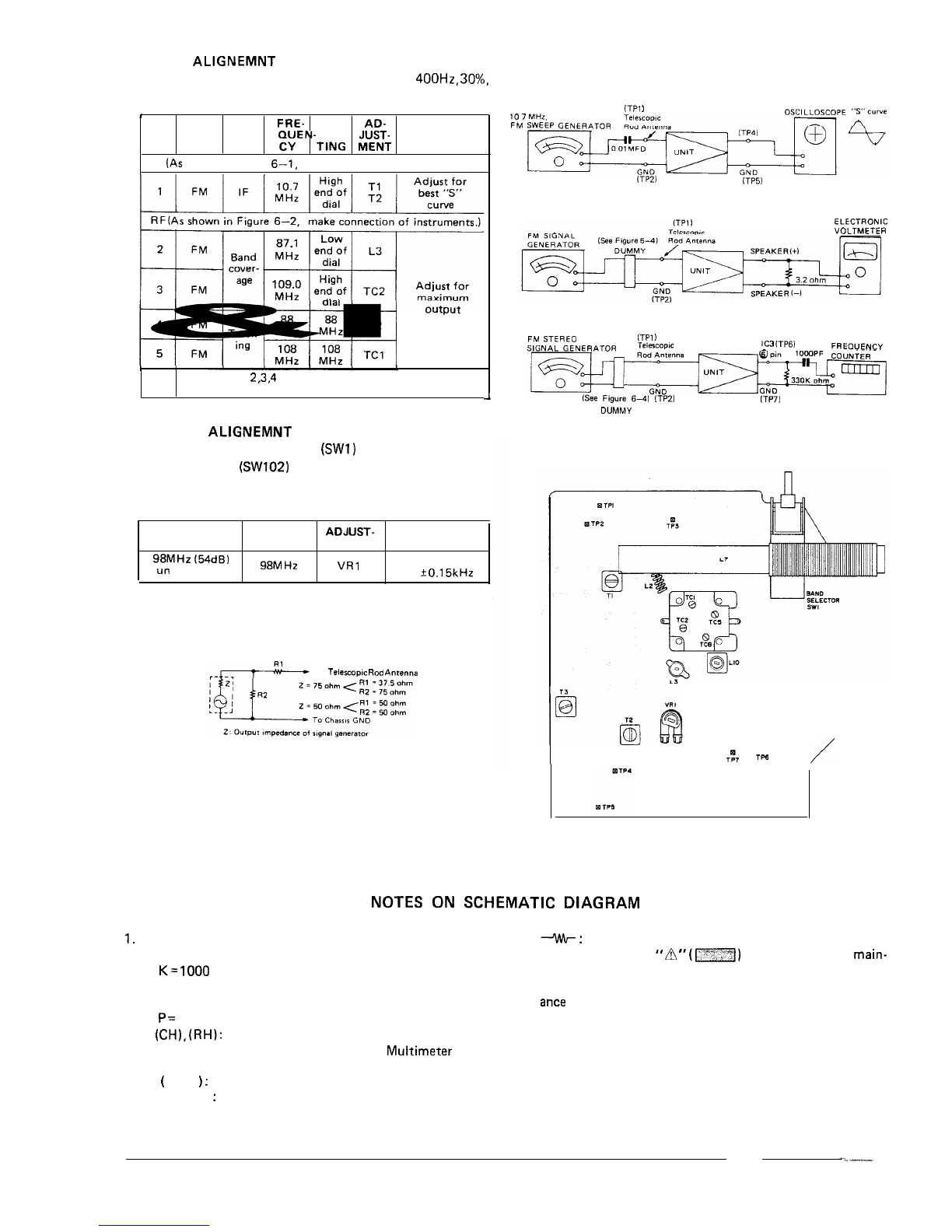
AM IF/RF ALIGNMENT
l
Set the signal generator to produce a signal of
400H2,
30%,
AM modulated.
l
For adjustments in steps 4, see
[Note1
.
STEP
EAND
STAGE
QUEN-
SETT- MENT
TEST FRE- DIAL ADJUST-
REMARKS
CY ING
IF (As shown in Figure 5-2, make connection of instruments.)
I
1
I I I I
1 1
I
I
1
I
RF (As shown in Fiqure 5-3, make connection of instruments.)
0
Repeat steps
2.3.4
and 5 until no further improvement
can be made.
4
GENERAL
ALIGNMENT
INSTRUCTION
Figure 5-2
ELECTRONIC
VOLTMETER
SIGNAL
GENERATOR
TEST LOOP
Figure 5-3
(Note/
Check the alignment of the receiver antenna coil by
bringing a piece of ferrite (such as a coil slug) near the antenna
loop stick, then a piece of brass. If ferrite increases output,
loop requires more inductance. If brass increases output, loop
requires less inductance. Change loop inductance by sliding the
bobbin toward the center of ferrite core to increase inductan-
ce, or away to decrease inductance.


 User manual")


 User manual")


 User manual")