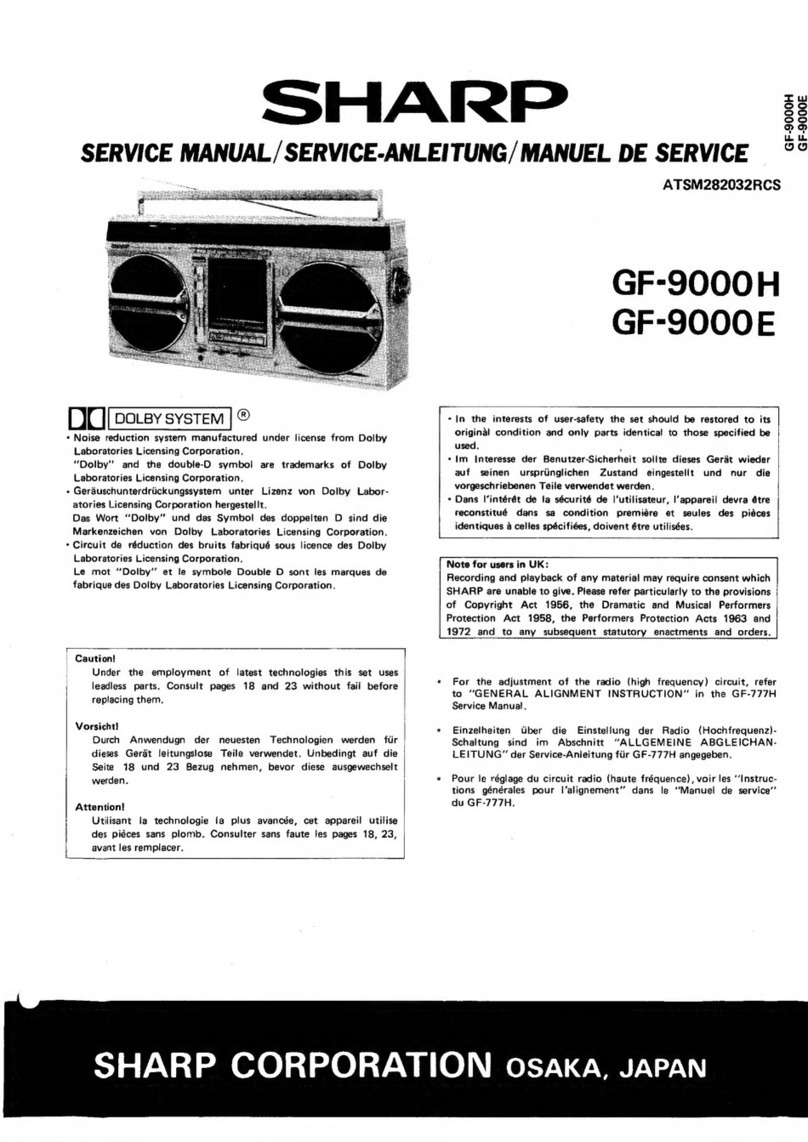
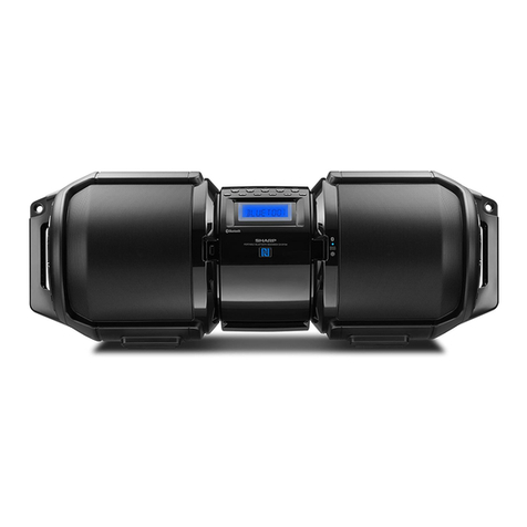
Sharp QT-50Z User manual

SHARI=
SERVICE MANUAL
!34429QT-50ZW/
QT-50Z(VV)
QT-50Z(P)
QT-50Z(GR)
Photo: QT-502(W)
In the interests of user-safety the set should be restored to its
original condition and only parts identical to those pacified be
used.
f
Page
SPECIFICATIONS..
.............................................2
NAMES OF PARTS ..............................................2
DISASSEMBLY .................................................3
VOLTAGE SELECTION ...........................................3
STRINGING OF DIAL CORD......................................4
MECHANICAL ADJUSTMENT ......................................4
CIRCUIT ADJUSTMENT ........................................
5,6
SCHEMATIC DIAGRAM. ........................................
7,8
NOTES ON SCHEMATIC DIAGRAM. .................................9
WIRING SIDE OF
P.W.BOARD
..................................9,
IO
EXPLODED
VIEW............................................11,12
REPLACEMENT PARTS LIST ..................................13
-
16
INDEX
TO
CONTENTS
-T
SHARP
CORPORATION

GENERAL
Power source:
Output power:
Semiconductors:
Dimensions:
Weight:
FOR A COMPLETE DESCRIPTION OF THE OPERATION OF THIS UNIT,
PLEASE REFER TO THE
OPERATlON
MANUAL.
SPECIFICATIONS
TAPE RECORDER
ACllOV-127Vand220V-
240 V,
50160
Hz
DC
9V
(UM/SUM-2
or
RI4
type
x6)
MPO; 7.2 W
(3.6W
+
3.6W)
(AC operation)
RMS;
4.6 W(2.3
W
+2.3 W)
(DC operation, 10% distortion)
PMPO; 14
W
(7
W
+7 W)
(AC operation)
5
ICS
1 Transistors
10 Diodes
2 LEDs
Width; 402 mm
(15-I
3/l
6”)
Height; 137 mm
(5-7/16”)
Depth; 81 mm (3-31’16”)
1.7 kg (3.75
Ibs.)
without batteries
Tape: Compact cassette tape
Frequency range: 50 Hz
-
10,000 Hz
Signal/noise ratio: 36
dB
Input impedance: External mic; 600 ohms
Output level and
loaded impedance: Headphones; 8 ohms
-
32 ohms
RADIO
Frequency range: AM; 526.5
kHz
-
1606.5
kHz
SW,;
2.3 MHz
-
7.3 MHz
SW
;
7.3 MHz
-
22 MHz
FM; 87.6 MHz
-
108
MHz
SPEAKERS
Speakers:
9 cm
(3-l/2”)
x
2
Specifications for this model are subject to change without
prior notice.
1.
Volume Control
2.
Balance Control
3. Tone Control
4. Function Selector Switch
5.
Pause Button
6. Stop/Eject Button
7. Fast Forward Button
8. Rewind Button
9. Play Button
10. Record Button
11. FM Mode Selector
12. Band Selector
NAMES
OF
PARTS
13. Tuning Control
14. Power Indicator
15. FM Stereo Indicator
16. Digital Tape Counter and Counter Reset Button
17. Cassette Compartment
18. Fine Tuning
19. Built-in Microphone
20. External Microphone Jacks
21.
FM/SW
Telescopic Rod Antenna
22. Headphones Jack
23. AC Power Supply Socket
24. Battery Compartment Lid
Figure 2-l FRONT PANEL Figure 2-2 REAR PANEL
l
This unit is provided with a carring belt, but it is not depicted in the following Figures.
-2-

DISASSEMBLY
l
This unit is provided with a carring belt, but it is not
depicted in the following Figures.
Caution on Disassembly
Follow the below-mentioned notes when disassembling the
unit and reassembling it, to keep its safety and excellent
performance:
1. Take cassette tape out of the unit.
2. Be sure to remove the power supply plug from the wall
outlet before starting to disassemble the unit and remove
the batteries from the unit.
3. Take off nylon bands or wire holders where they need
be removed when disassembling the unit. After servicing
the unit, be sure to rearrange the leads where they were
before disassembling.
4. Take sufficient care on static electricity of integrated
circuits and other circuits when servicing.
STEP
REMOVAL
PROCEDURE
1
Front cabinet 1. Battery compart-
ment lid. . . . . .
(A)
x
1
ZScrew..
. . . .
(B)x6
3. Open the cassette
holder. . . . . .
(C)
4. Open the
2
3
Mechanism block 1. Tape counter drive
Main
P.W.Board
cabinet . . . . . . (D)
5. Socket. . . . . .
(E)
x
1
belt . . . . . . . .
(F)
x
1
2. Screw . . . . .
IG)
x
2
3. Socket. . . . (HI
x
2
l.Screw.
. . . . . .
(11x8
2. Tip. . . . . . . .
(J)
x
2
I
3-2
3-3
3-4
*
Set the mechanism in such a way as that the record/play-
back selector lever is positioned as shown in Fig. 3-5.
Figure 3-5
VOLTAGE
SELECTION
Before operating the unit on mains, check the preset voltage.
If the voltage is different from your local voltage, adjust the
voltage as follows: Slide the AC power supply socket cover by
slightly loosing the screw to the visible indication of the side
of your local voltage.
Figure 3-l
Figure 3-2
fFixl
Mechanism Block
d
(Glx2
Figure 3-3
Main
P,W.B.
Record Playback Selector Spring
Figure 3-4
-3-
STRINGING
OF
DIAL
CORD
Pulley
(227)
1. Turn the drum fully in the direction A shown in Fig.
4-1
and stretch its cord over the parts in the numerical order.
2. The turn the tuning control shaft fully in the direction
B
shown in Fig. 4-l and fix its pointer as shown in Fig. 4-2.
Figure 4-l
MECHANICAL ADJUSTMENT
E.V:
ELECTRONIC VOLTMETER
DUAL-TRACE
SY
NCROSCOPE
ITEM USING JIG
I
ADJUSTMENT REMARKS (CHECK)
POINTS
More than 150
g
Tape
tention
megurering
cassette
TW-2412
Torque meter
Play
-rw-2111
Fast-forward
TW-2231
Rewind
TW-2231
Driving
power
Torque
(Play:
30-60
g-cm)
(Fastforward
:
80-140
g-cm)
(Rewind
:
80-l
40 g-cm)
1
HEADPHONES
JACK
IRIGHT)
Figure 4-3 AZIMUTH
RECORD/PLAYBACK HEADPHONES
..-..
FRECXJENCY
HEAD
.lAtiK
PLAY BACK
/
COUNTER
M
Azimuth
Tape
spa&
TEST TAPE
m-r-1
11
Figure 4-4 TAPE SPEED
TEST TAPES
1
TORQUE METER
FOR
COMPACT
CASSETTE COMPACT
CASSETTE TYPE
TITLE
FLUTTER
MODEL
FREQUENCY/
LEVEL APPLICATION
Tape
speed,
MTT-111
3
kHr,
-10
-10
Wow and flutter
check
MODEL MEASUREMENT
RANGE APPLICATION
TW-2111
lo-
16Ogcm
Normal
:
Playback torque
1.5-log-cm
Normal
:
Back
tension
TW-2121
lo-
1OOgcm
Reverse
:
Playback torque
1.5
-
log-cm
Reverse
:
Back tension
TW-223 1
30
-
200 g-cm Fast-forward, Rewind torque AZIMUTH
MTT-113 6.3 kHz,
-10
dB
MTT-113C
8 kHz, -10 d6
Head
arimuth
MTT-I 14
10
kHz, -10 d6 adjustment
DISTORTION
MTT-118
1 kHz, -10
dB
Distortion check
level adjustment
TW-2412
o-3oog
TW-2422
o-3oog
Normal
:
Driving power
Reverse
:
Driving power
1
U&‘L’ELI
MTT-150
1
Dolby
B-Type
/
DoIN
NR
B-type
1
Tone 200
m&/m
level adlustment
BLANK MTT-502 Record frequency
-
check
-4-

SE-ll-ING
Volume control: Maximum Balance
controk
Center
POSITION OF
Tonecontrol:CenterFunctionselector switch: Tape
SWlTCH
AND
KNOB
I
ITEM
/
INPUT
/
ADJI.$-
1
REMARKS (CHECK)
(
PLAYBACK AMP- Test
tape
LIFIER
1.35v
SENSITIVITY
NTT-11
BN
AM
LF/RF
ADJUSTMENT
CIRCUIT
ADJUSTMENT
(TUNER
SECTION)
IIGNAL
GENERATDR
400 Hr. 30%. AM modulated
FRE-
DIAL
AD
TEf
SyAyE
QUE-
POINTER
JUST-
REMARKS
NCY SElTlNG
MENT
4M
IF
AM RF
SWt
RF
SWz
RF
Figure 5-l PLAYBACK AMPLIFIER SENSITIVITY
Lowest
7
2.25
L7
Band
MHZ
frequency
coverage
87.4MHz Highest
frequency TC4 Adjust for
maximal output.
9
2.6 MHz
2.6 MHz
L4
-
Tracking
10 6.0 MHz
6.0 MHz
TC3
11
Repeat steps
7,B,9
and 10 until no further
improvementcanbemade.
Figure 5-2 AM IF
Figure 5-3 AM RF
Figure 5-4 SW RF

FM IF/RF ADJUSTMENT
FM mono
4OOHz.
30%. FM modulated
-
DIAL
‘OINTEF
;ElTlNG
High
frequency
I
I.
i
I
i
‘ur
until no
i
turn the core of
T2
counter-clockwise
before taking it out
oi
this bobbin.
2.Adjust for best “IF”
Figure 6-l FM IF
1
IF
I
I
10.7
MH
Y
-%7-
curve.
T2
IAdjust
for
best”S’
curve.
ther improvement can be made.
Lowest
frequency
10.7 MHZ
Highest
Adjust for maximal output
Figure 6-2 FM “IF” CURVE Figure 6-3 FM “S” CURVE
88 MHz
108
MHz
8
IRepeat
steps
4.
5
and
6.
7untilnofurtherImprovementcanbemade
;I
I
O
1
=
GND GNO
VCO FREQUENCY ADJUSTMENT
Figure 6-4 FM RF
SIGNAL GENERATOR
400 Hz, 30%. FM unmodulated
(monosignal)
DIAL
FREQUENCY POINTER
ADJUST-
MENT
REMARKS
SETrING
FM
IC3
SlGNAL
GENERATOR
FREO"UENCY
COUNTER
52
(See
c&e$-6)
Figure 6-5 FM STEREO
FM mono position
98 MHz at 54
dB
98 MHz
FM stereo position
(unmodulated)
VRl
Adjust for 19.00
kHz
+
200
Hz.
Figure 6-6 FM DUMMY
t
TPl
Figure 6-7 ADJUSTMENT POINTS
-6-

1
I
2
I
3
I
4
I
5I6
-
--
MAIN P.W.B. CIRCUIT
&TX
.:“p
iMYl
.oz
CC”1
T
l
NOTES ON SCHEMATIC DIAGRAM can be found on page 9.
1I
2
I
3
I
4
I
5
I
6
Figure 7
SCt-
-7-

m
B
I I
I
i-
I
I

-
A
B
C
D
E
F
G
~
H
1
I
23
I
4
I
5
I
6
I
MAIN PWB
NOTES
ON
SCHEMATIC
DIAGRAM
l
Resistor:
To differentiate the units of resistors, such symbol as
K
is
used: the symbol
K
means 1000 ohm and the resistor
without any symbol is ohm-type resistor.
0
Capacitor:
To indicate the unit of capacitor, a symbol
P
is used:
this symbol
P
means micro-micro-farad and the unit of
the capacitor without such a symbol is microfarad. As
to electrolytic capacitor, the expression “capacitance/
withstand voltage” is used.
l
The indicated voltage in each section is the one measured
by Digital
Multimeter
between such a section and the
chassis with no signal given.
(
1:
AM mode
Marking except for
(1:
FM mode
l
Schematic diagram and Wiring Side of P.W.Board for this
model are subject to change for improvement without prior
notice.
. Parts marked with “
A”
(
-,‘)
are important for main-
taining the safety of the set. Be sure to replace these parts
with specified ones for maintaining the safety and per-
formance of the set.
1
I
2
I
3
I
4
I
5
I
6
I
Figure 9 WIRING SIDE OF
-9-

I
7
I
8
I
9
I
10
I
11
I
12
@
0
--+
/
r-
-o-
II
the
r
this
main-
parts
I
per-
I
7
I
8
I
9
I
10
I
11
I
12
G
SIDE
OF
P.W.BOARD
-lO-

A
85
86
.-
75-m
79
B
1
I
2
I
3
I
4
I
5
I
58
E
9
96
““-9
57-
/--
I
lb
F
c
1
1
2
I
3
I
4
I
5
1
Figure 11 MECHANISM EXPLODED VIEW
-ll-

A
B
c
D
E
F
G
H
-
1
I
2
I
3
I
4
I
5
I
6
204
201-
243\
242-
L
1
a
I
Figure 12 CABINET
EXPLODED
VIEW
I
Y
I
VJ
-12-

REPLACEMENT PARTS LIST
“HOW
TO
ORDER
REPLACEMENT
PARTS”
To have your order filled promptly and correctly, please furnish the following information,
1. MODEL NUMBER 2. REF. NO.
3. PART NO. 4. DESCRIPTION
Parts marked with
“8”
are important for maintaining the safety of the set. Be sure to replace these parts with
specified ones for maintaining the safety and performance of the set.
REF. NO.
ICl
IC2
IC3
ICl 01
IC102
Q301
Dl
D2
03
D4
Dl
01
D102
D301
D302
D303
D304
D305
D306
Ll
L2
L3
L4
L5
L6
L7
L8
L310
Tl
T2
CFl
CF2
PART NO.
DESCRIPTION CODE
INTEGRATED CIRCUITS
VH
IBA4402//-
1
FM Front-End (BA4402)
VHIAN7224//-1 FM IF/AM Circuit (AN7224)
VHIBA1332L/-1 FM Multiplex
(BAl332L)
VHITA7668BP-1
Pre Amp.
(TA7668BP)
RH-IX1267AFZZ Power Amp. (TA7233AP)
TRANSISTORS
AF
AH
AG
AK
AK
VS2SC1815GR1 Silicon,
NPN.
2SC1815
GR
DIODES
AB
VHDI
SSI
19//-l
Silicon, 1
SSI
19
VHDI
SSll9//-1
Silicon,
1
SSl 19
VHPGL3PRl//-1 LED, Red, GL-3PRl
VHDl
SSl
19//-l
Silicon, 1
SSI
19
VHDI SS119//-1 Silicon, 1
SSl
19
VHDI SS119//-1 Silicon, 1
SSl
19
VHDS5566G//-1 Silicon, S5566
VHDS5566Gff-1 Silicon, S5566
VHPGL3PRl//-1 LED, Red, GL-3PRl
VHERD5RGJBS-1
Zener
5.6Vl400mV.
RD5.6JB3
AA
AA
AC
AA
AA
AA
A6
AB
AB
AB
AC
AB
COILS
RCILA0652AFZZ
FM Band PASS Filter
RCILB0672AFZZ FM RF
RCILB0703AFZZ
FM Oscillator
RCIlA0692AFZZ Bar Antenna, SWI/AM
RCILA0556AFZZ
SW2
Antenna
RClLB0623AFZZ AM Oscillator
RCILB0624AFZZ SWi
Oscillator
RCILB0625AFZZ
SW2
Oscillator
RCILF0014AGZZ
47
PH.
Choke
TRANSFORMERS
AD
AC
AC
AL
AD
AC
AC
AC
AB
RCILIO157AFZZ
FM IF
AC
RCILIO312AFZZ
FM Detector
AC
RClLlO31
OAFZZ
AM IF
AC
RTRNP1028AFZZ
POWER Transformer
AQ
FILTERS
RFlLFOl
OGAFZZ
Ceramic, FM IF, 10.7MHz
RFILA0085AFZZ
Ceramic, AM IF, 455kHz
AC
AE
REF.NO.
PART NO.
DESCRIPTION
CONTROLS
CODE
vc1.2,
vc3,4.
TC1.2
TC3,4
TC5
RVC- R0083 AFZZ
Variable Capacitors, Tuning
AN
RTO-H1072AFZZ
AC
TC6
RTO-H1072AFZZ
AC
TC7
RTO-H1072AFZZ
TC8
RTO-HI 072AFZZ
vc5
VRl
VRI
01
VR102
VRI 03
RVC-Z0062AFZZ
RVR-M0390AFZZ
RVR-ZO178AFZZ
with Trimmers
Trimmer, AM Antenna
Trimmer
Trimmer, AM Oscillation
Trimmer
Trimmer,
SW2
Antenna
Trimmer
Trimmer,
SWz
Oscillation
Trimmer
Fine Tuning
5
kohms(B),
V.C.O. Adjust
20
kohms(B),
Volume Control
AC
AC
AF
AB
AG
RVRZO179AFZZ 50
kohms(W),
Balance Control AE
RVR-AO192AFZZ
50
kohms(A),
Tone Control
AE
ELECTROLYTIC CAPACITORS
(Unless
otherwise
specifiedelectrolyticcapacitorsare
f20%
type.)
Cl3
Cl6
Cl8
c34
c35
c44
C63
C72
C80
C84
C85
c91
c92
Cl13
Cl14
Cl21
Cl 22
Cl 27
Cl28
Cl42
Cl43
Cl45
Cl 47
Cl 49
Cl81
Cl82
Cl85
Cl86
Cl87
Cl 88
Cl 89
Cl 90
Cl 93
RCEZD476AFl A
RCEZA106AFl
C
RCEZA106AFl
C
RC-EZA107AFl A
RCEZA475AFl
E
RC-EZA476AFl A
RCEZA476AFl
A
RC-EZA106AFl
C
RC-EZA105AFl
H
RC-EZA474AFl
H
RCEZA474AFl
H
RC-EZA104AFl
H
RC-EZA104AFl
H
RC-EZA475AFl
E
RCEZA475AFl
E
RC-EZA226AFl
C
RCEZA226AFl
C
RC-EZA104AFl
H
RC-EZA104AFl
H
RC-EZA106AFl
C
RC-EZA334AFl
H
RC-EZA476AFl A
RCEZAl07AFl
A
RC-GZA337AFl
C
RCEZA105AFl
H
RCEZA105AFl
H
RC-EZA476AFl A
RC-EZA476AFl A
RCEZA107AFl
A
RC-EZAI
07AFl
A
RCEZ1268AFZZ
RC-EZ1268AFZZ
RCEZl224AFZZ
47pF,
1OV
10 pF, 16V
10 pF, 16V
100 pF, IOV
4.7
,uF,
25V
47pF,
1OV
47
,uF,
IOV
10 pF, 16V
1
PF.
50V
0.47 pF, 50V
0.47
/LF,
50V
0.1 pF, 50V
0.1 pF, 50V
4.7 pF, 25V
4.7
I”F,
25V
22 pF, 16V
22 pF, 16V
0.1 pF, 50V
0.1
PF.
50V
10 pF, 16V
0.33
,uF,
50V
47 pF,
1OV
100 pF,
1OV
330
~1
F,
16V
1 pF, 50V
1
PF.
50V
47
PF.
1OV
47
/.LF,
1OV
100
,uF,
IOV
100 pF,
1OV
330
,uF,
1OV
330
,uF,
1OV
100 pF,
1OV
AC
AB
AB
AB
AB
AB
AB
AB
AB
AB
AB
AB
AB
AB
AB
AG
AG
AB
AB
AB
AB
AB
AB
AC
AB
AB
AB
AB
AB
AB
AB
AB
AB
-
13-
REF.NO.
PART NO.
DESCRIPTION
CODE
c305
RC-EZA476AFl A
47 pF, IOV
AB
C306
RC-EZA107AFl A
100 pF, IOV
AB
C3OB
RC-EZ1267AFZZ
2200 pF, 16V
AE
c310
RC-EZAl07AFl
C
100 pF, 16V
AB
CAPACITORS
(The terms CM, SC, and ST used here indicate the types of capacitor ceramic type,
semiconductor type and styrol
type.)
(Tubular-shaped type chip capacitor is identified by the symbol MF of the part No.
VC..MF....;
this MF does not mean the lead wire.1
Cl
VCCSMFl
HLlBOJ
18
pF,
5OV,
f5%,
CM
AA
c2
VCCCMFI HH200J 20
pF(CH),
5OV.
f5%,
CM
AA
c4
VCCCMFl
HH150J 15
pF(CH),
5OV,
f5%,
CM
AA
c5
VCCCMFI
HHlOOJ
10
pF(CH),
5OV.
+5%,
CM
AA
c7
VCCCMFl
HH180J 18
pF(CH),
5OV,
+5%,
CM
AA
C8
VCCCMFI
HH2R2C
2.2
pF(CH),
5OV,
f0.25 pF, AA
CM
c9
Cl0
Cl 1
Cl2
Cl4
Cl5
Cl7
c31
C36
C38
c39
c40
c43
c45
c51
c54
VCTYMFl HV472N 0.0047 pF,
5OV.
+30%,
SC AA
VCTYMFlCY223N 0.022 pF,
16V,
-1-30%.
SC AA
VCTYMFl
HV472N
0.0047
/.LF,
5OV,
t30%,
SC
AA
VCl-YMFl
EX103N
0.01 pF,
25V,
+30%,
SCAA
VCTYMFl
HV472N
0.0047 pF,
5OV,
f30%,
SC
AA
VCTYMFlCY223N 0.022
pF,
16V,
+-30%,
SC AA
VCTYMFl
CY223N
0.022
pF,
16V,
+30%,
SC
AA
VCTYMFI
CY223N
0.022
PF.
16V,
f30%,
SC AA
VCCSMFl
HL470J
47
pF,
5OV.
+5%,
CM
AA
VCTYMFlCY223N 0.022
pF,
16V,
f30%,
SC
AA
VClYMFlCY223N
0.022
pF,
16V.
+309/o,
SC AA
VCTYMFlCY223N 0.022
pF,
16V,
f30%,
SC AA
VCKYMFl HB221
K
220
pF,
5OV,
&IO%,
CM
AA
VCTYMFlCY223N 0.022 pF,
16V.
230%.
SC AA
VCTYMFlCY223N 0.022
pF,
16V,
f30%,
SC AA
VCCCMFl
HH5R6D
5.6
pF(CH),
5OV,
f0.5 pF, AA
CM
c55
c57
C58
VCCSMFl
HL2R2C
2.2
pF,
5OV,
f0.25 pF,
CM
AA
VCCCMFI HH120J 12
pF(CH),
5OV,
x!z5%,
CM
AA
VCCCMFI
HH6RBD
6.8
pF(CH),
5OV,
f0.5 pF,
AA
CM
c59
VCCCMFl
HH8R2D
8.2
pF(CH),
5OV,
+0.5
pF,
AA
CM
C61
C62
C63
C64
c73
c74
c75
C86
C87
VCTYMFl CY223N
0.022
,uF,
16V.
+-30%.
SC AA
VCKYMFl HB361
J
360
pF,
5OV,
&5%, CM
AA
VCl-YMFl HV152K 0.0015 pF,
5OV,
flO%,
SC AA
VCl-YMFl HV472K 0.0047
PF.
5OV,
+I
0%. SC AA
VCTYPAl
EX473M 0.047
pF,
25V,
+20%,
SC AA
VCTYMFlCY223N 0.022
FF.
16V,
f30%,
SC AA
VCTYMFlCY223N 0.022
,uF,
16V,
f30%,
SC AA
VCQSMAI HL102J
0.001
pF,
5OV,
f5%,
ST
AB
VCKZPVI
HF472Z 0.047
pF,
5OV.
+BO-20%.
AA
CM
Cl 05
Cl 06
Cl 09
Cl10
Cl
11
Cl12
Cl15
Cl16
Cl17
Cl18
Cl 25
Cl 26
Cl29
Cl 30
Cl91
Cl92
Cl32
Cl51
Cl 52
VCKYMFl HB102K 0.001
pF,
5OV,
&IO%,
CM AA
VCKYMFI HB102K
0.001
pF,
5OV,
+lO%,
CM AA
VCKYMFl HB221
K
220
pF,
5OV,
flO%,
CM
AA
VCKYMFl HB221
K
220
pF,
5OV,
+lO%,
CM
AA
VCTYMFl EXlO3N 0.01 pF, 25V,
+30%,
SC
AA
VCTYMFI EXlO3N 0.01 pF, 25w,
+30%,
SC
AA
VCCSMFl
HL470J
47
pF,
5OV.
+5%,
CM
AA
VCCSMFl
HL470J
47
pF,
5OV.
+5%,
CM
AA
VCTYMFlCY223M 0.022 pF,
16V.
f20%,
CM AB
VCTYMFlCY223M 0.022 pF,
16V,
f20%,
CM AB
VCTYMFl
HV472N
0.0047 pF,
5OV,
f30%,
SC AA
VCTYMFI
HV472N
0.0047
ELF,
5OV,
+30%,
SC AA
VCTYMFI
HV272K 0.0027
/.LF,
5OV.
flO%,
SC AA
VCTYMFl HV272K 0.0027 pF,
5OV,
flO%,
SC AA
RC-QZA154AFYK
0.15 pF, 25V,
flO%,
ML AC
RC-QZA154AFYK
0.15 pF, 25V,
flO%,
ML AC
VC-WMFJC’f223N 0.022
pF,
16V.
+309/a,
SC AA
VCKYMFl
HBI
81
K
180
pF,
5OV.
It1
0%,
CM
AA
VCKYMFl
HB181
K
180
pF,
5OV,
+lO%,
CM
AA
REF.NO.
PART NO.
DESCRIPTION
CODE
Cl67 VCTYPAlEX473M 0.047
pF,
25V.
t20%,
SC AA
Cl 68 VCTYPAI EX473M 0.047 pF,
25V.
&20%,
SC AA
Cl 69 VCTYMFl HV472M 0.0047
/.LF,
50V.
+20%,
SC AA
Cl 70
VCTYMFl
HV472M 0.0047
/.LF,
50V.
f20%.
SC AA
Cl71 VCTYPAI EX473M 0.047
/.LF,
25V.
+20%,
SC AA
Cl 72 VCTYPAI EX473M 0.047 pF,
25V.
&20%,
SC AA
Cl 83 VCKYMFl HB221
K
220
pF,
5OV,
&IO%,
CM
AA
Cl84 VCKYMFl HB221
K
220
pF,
5OV.
tlO%,
CM
AA
Cl91
RC-QZA154AFYK
0.15 pF,
25V,
+100/o,
ML AC
Cl 92
RC-QZA154AFYK
0.15
PF.
25V.
flO%,
ML AC
c301
VCKYMFl HD102M 0.001 pF,
5OV.
+20%.
CM AA
C302 VCKZPAl
HF473Z 0.047
pF,
5OV.
+80-20%.
AA
CM
c303
c304
VCKYMFl HDlOPM
0.001
pF,
5OV,
+20%,
CM AA
VCKZPVI
HF473Z 0.047 pF,
50V.
AB
+80-20%,
CM
c307
VCTYMFl
CY223N 0.022 pF,
16V,
+-30%, SC AA
c309
VCTYMFlCY223N 0.022 pF,
16V.
f30%,
SC
AA
c311
VCTYMFl
HV272N 0.0027 pF,
5OV.
+30%,
SC AA
RESISTORS
(Unless
otherwise
specified, resistors are
1/4W,
&50/o.
carbontype.)
(Tubulartype
carbon film resistor(l/4W,
f5%)
is identified bythesymbol
MF of
the
hart
N
O
.
VRD-MFOO00000;
this MF does not mean lead wire.)
RI
Rl
1
R12
R13
R16
R17
R31
R36
R37
R42
R44
R50
R55
R72
R74
R75
R76
R78
R79
R85
R86
Rl
01
RI02
R103
RI04
R109
RI
10
R115
R116
R119
R120
RI 21
RI 22
RI 23
RI 24
R129
RI 30
R131
RI 32
R133
VRD-MF2EE220J
VRD-MF2EE391
J
VRD-MFZEEl22J
VRD-ST2CD221
J
VRD-MF2EE822J
VRD-ST2CDB24J
VRD-MF2EE331
J
VRD-MF2EE222J
VRD-MF2EE471
J
VRPMF2EE272J
VRD-MF2EE680J
VRD-MF2EE330J
VRD-MF2EElOl
J
VRD-ST2CDl22J
VRD-MF2EE392J
VRD-MF2EE392J
VRD-ST2EE561
J
VRD-ST2CD561
J
VRD-MF2EE103J
VRD-MF2EE102J
VRD-MF2EE912J
VRD-MF2EE822J
VRD-MF2EE822J
VRD-MF2EE820J
VRD-MF2EE820J
VRD-MF2EEl22J
VRD-ST2EE122J
VRD-MF2EE274J
VRD-ST2CD274J
22 ohms
390 ohms
1.2 kohms
220 ohms, 1/6W, &5%,
Carbon
8.2 kohms
820 kohms, 1/6W, C5%,
Carbon
330 ohms
2.2 kohms
470 ohms
2.7 kohms
68 ohms
33 ohms
100 ohm
1.2 kohms, 1/6W,
+5%,
Carbon
3.9 kohms
3.9 kohms
560 ohms
560 ohms, 1/6W,
f5%,
Carbon
10 kohm
1 kohm
9.1 kohms
8.2 kohms
8.2 kohms
82 ohms
82 ohms
1.2 kohms
1.2 kohms
270 kohms
270 kohms, 1/6W, &5%,
Carbon
8.2 kohms
8.2 kohms
82 ohms
82 ohms
56 kohms
56 kohms
15 kohms
15 kohms
15 kohms
15 kohms
1 kohm
VRD-MF2EE822J
VRD-MF2EE822J
VRD-ST2EE820J
VRD-MF2EE820J
VRD-MFZEE563J
VRD-MF2EE563J
VRD-MF2EE153J
VRD-MFLEE153J
VRD-MF2EE153J
VRD-MF2EE153J
VRD-MF2EE102J
AA
AA
AA
AA
AA
AA
AA
AA
AA
AA
AA
AA
AA
AA
AA
AA
AA
AA
AA
AA
AA
AA
AA
AA
AA
AA
AA
AA
AA
AA
AA
AA
AA
AA
AA
AA
AA
AA
AA
AA
-14-
REF. NO.
R134
R135
RI 36
R141
RI42
R143
R145
R146
R148
R149
R150
R161
R162
R165
R166
R’l67
RI 68
R171
R172
R185
RlB6
R189
1
RI90
R305
R306
Bll
01
QCNW-2451 AFZZ
CNSl
01
QCNW-2454AFZZ
CNS102
QCNW-2455AFZZ
CNS103
QCNW-2456AFZZ
CNPl
01 QCNCM586EAFZZ
CNPl02
QCNCM588GAFZZ
CNPI
03
QCNCM584CAFZZ
Jl
01
QJAKEO124AFZZ
J102 QJAKEOl24AFZZ
J103
MO201
nso3o1
SW301
I
SPl VSPDO9OP-13SA
SP2
VSPDO9OP-13SA
SW1
QSW-BO183AFZZ
SW2 QSW-PO502AFZZ
SW1
01
QSW-P0538AFZZ
SW1
02
QSW- S0430AFZZ
SW201
94RLSA-1120RC
SW202
94RMSW-1259T
2
3
6
7
8
9
10
11
12
13
14
18
PART NO.
DESCRIPTION
VRD-MF2EE102J
1
kohm
VRD-ST2EE332J
3.3 kohms
VRD-MF2EE332J 3.3 kohms
VRD-MF2EE561
J
560 ohms
VRD-STZEEI
02J 1 kohm
VRD-MF2EE102J 1 kohm
VRD-MF2EE222J 2.2 kohms
VRD-MF2EE105J 1 Mohm
VRD-ST2EE103J
10 kohm
VRD-ST2EE560J
56 ohms
VRD-MF2EE102J
1
kohm
VRD-MF2EE472J 4.7 kohms
VRD-MFZEEI
01
J
100 ohm
VRD-ST2EEl 01
J
100 ohm
VRD-MF2EE472J 4.7 kohms
VRD-MF2EE272J 2.7 kohms
VRD-
MFZEEl01
J
100 ohm
VRD-MF2EElOl
J
100 ohm
VRD-MF2EElOl
J
100 ohm
VRD-MFZEEI 01
J
100 ohm
VRD-MF2EE681
J
680 ohms
VRD-MFZEEI
02J 1 kohm
CIRCUIT PARTS
QJAKJOl45AFZZ
RMOTVO165AFOl
2Pin Bord in Plug Assembly
5Pin Socket Assembly
7Pin Socket Assembly
3Pin Socket Assembly
Plug,
5Pin
Plug, 7Pin
Plug, 3Pin
External Microphone Jack
(
Left)
External Microphone Jack
(Right)
Headphones Jack
Motor Assembly
QSOCE0595AFZZ
Socket, AC Power Supply
(with AC/DC Selector
Switch)
Speaker
Speaker
Switch, Slide Type
Switch, Push Type
Switch, Push Type
Switch, Slide Type
Switch, Leaf Type
Switch, Leaf Type
MECHANICAL PARTS
94R180001501
94R15100202
94R18000201
94R18000306
94R18000305
94R180003305
94R144003
15
94R18000307
94R180001404
94R180004305
94RlBOOO405
Main Shassis Assembly
Lever, Record/Playback
Selector
Lever, Erase Prevention
Sub-Chassis
Head Base
Lever, Auto Stop Sensor
Spring, Head Azimuth
Spring. Over Stroke
Spring, Cue/Revew
Pinch Roller Assembly
Spring, Pinch Roller
CODE
AA
AA
AA
AA
AA
AA
AA
AA
AA
AA
AA
AA
AA
AA
AA
AA
AA
AA
AA
AA
AA
AA
AA
AA
AA
AC
AF
AF
AF
AB
AB
AA
AC
AC
AF
AT
AG
AN
AN
AM
AE
AG
AF
AE
AE
AQ
AC
AC
AD
AD
AD
AB
AB
AC
AG
AC
AC
94R17152015
Stop Washer, Pinch Roller
94RlBOOO6314 Roller, Fast Forward/Rewind AK
Assembly
REF.NO.
PART NO.
19
94R180006504
20
94R18000635
21
94R18000608
22
94Rl8000609
24
94R18000610
26
94R180007317
27
94R180000726
28
94R12000906
29
94R18000707
31
94
R180005303
32
94R18000508
34
94R180005302
35
94R18000507
37
94R18001005
39
94R18001010
40
94R5880910
41
94R12001201
43
94R5630902
46
94R18001114A
47
94R18001123
48
94R18001103
50
94R18000934
51
94R18000935
52 94R180009501
53 94
RI
8000909
54 94R18000941
55
94R18000942
56
94
R18000940
57
94R18000902
58
94R18000903
59
94R18000905
60
94R18000907
61
94R18000957
62
94R180009334
63 94
RI
80009348
64
94R17000920
65
94R18000917
66
94R18000952
67
94R12221702
68
94R180009118
69
94R18201032
71
94R17000107
73 94RlBOO1406
74
94R18001412
75 94RlBOO1402
76 94RlBOO1407
77 94R18001411
79
94R18200312
80
94R91810000
81
94R90770000
82
94R91800000
83
94R90390000
84
94R92120000
85
94R98200000
86
94R98210000
87
94R91910000
88
94R96610000
90
94R97170000
91
94R93330000
DESCRIPTION
CODE
Lever, Playback Idler
AE
Idler. Playback
AE
Spring, Playback Idler
AC
Spacer, Playback Idler A0
Gear, Fast Forward
AD
Flywheel Assembly AK
Bracket, Flywheel
AE
Bracket, Flywheel
AB
Spring, Flywheel
AC
Turntalble, Take-Up Assembly AG
Spring, Take-Up Turntable
AB
Turntable, Supply Assembly AG
Spring, Supply Turntable
AB
Bracket, Motor
AD
Belt, Motor Drive
AG
Cushion, Motor
AB
Screw, Motor
AB
Cushion, Vibration Prevention AC
Lever, Cassette Holder
AC
Release
Spring, Cassette Holder
AB
Release Lever
Spacer, Cassette Holder
AA
Release Lever
Chassis, Button Operation
AF
Lever(Right)
Chassis, Button Operation
AF
Lever(Left)
Lever, Pause Lock Assembly AE
Lever, Stop/Eject
AC
Lever, Fast Forward
AD
Lever, Rewind
AD
Lever, Playback
AC
Lever, Record
AC
Spring, Record/Playback/ AC
Stop Lever
Spring, Rewind Lever
AC
Spring, Fast Forward Lever
AC
Spring, Pause Lock Lever
AC
Lever, Button Lock Assembly AD
Spring, Button Lock Lever
AB
Shaft, Button Lock Lever( Left) AB
Shaft, Button Lock Lever
AC
(Right)
Lever, Record Joint
AB
Lever, Pause Lock Selector
AC
Spring, Pause Lock Selector AC
Lever
Stop Washer, Pause Lock AA
Selector Lever
Spring, Cassette Pressure
Lever, Switch Joint
Lever, Timing
Lever, Panel Return
Spring, Panel Return Lever
Lever, Cue/Revew Arm
Spring, Timing Lever
Screw, 2mm Dia.
X
5mm
Screw, 2mm Dia.
x
4mm
Screw, Taptite, 2mm Dia.
X
4mm
AC
AC
AC
AC
AB
AC
AA
AA
AA
AA
Screw, 2.6mm Dia.
x
5mm
AA
Screw, 2mm Dia.
x
7mm
AA
Screw, 2mm Dia.
x
7mm AA
Screw, 2mm Dia.
X
8mm AA
Screw, 2.6mm Dia.
X
4mm
AA
Screw, 2mm Dia.
X
5mm
AA
Screw, 2mm Dia.
X
9mm
AA
Washer, 2.4mm Dia.
X
7mm
AA
Dia.
X
0.2mm
-
15-

REF. NO.
PART NO.
92
94R97930000
93
94R94210000
94
94R93120000
95
94R93610000
96
94R97760000
97
98
99
100
101
102
103
104
105
106
94R97180000
94R98610000
94R17001202
94R97930000
JKNBM0554AFSA Button, Stop/Fast Forward/
Rewind
JKNBM0554AFSB Button, Playback
JKNBM0555AFSA Button, Record
JKNBM0555AFSB Button, Pause
RHEDA0102AFZZ
Head, Erase
RHEDHOI
36AFZZ Head, Record/Playback
CABINET PARTS
201
201
201
CCAB-1315AFOl
Front Cabinet Combined
Assembly,
(W)
CCAB-1315AF03 Front Cabinet Combined
Assembly,(P)
CCAB-1315AF05 Front Cabinet Combined
202
202
202
203
204
204
GFTA-0013AFSB
204
GFTA-001
BAFSC
204-I
204-l
r
204-I
204-2
205
205
205
206 HINDP1049AFSA
206
HINDPI
053AFSA
206
HINDPI
054AFSA
207
HPNLDI
246AFSA
208
HSSNDO343AFSA
209 JKNBK0333AFSA
210 JKNBM0553AFSA
211
JKNBZ0363AFSA
212
KCOUBOI
63AFZZ
213 lANGK0282AFZZ
214
LANGZOI
01
AFZZ
215
LHLDFI
309AFSA
216
LHLDWI
075AFZZ
218
LXCZOD22AFZZ
DESCRIPTION CODE
Washer, 1.6mm Dia.
AA
X
3.4mm Dia.
X
0.3mm
Washer, 1.2mm Dia.
x
3mm AA
Dia.
x
0.25mm
Washer, 2.1 mm Dia.
X
5mm AA
Dia.
X
0.5mm
Washer, 1.55mm Dia.
AA
X
5mm Dia.
X
0.5mm
Washer, 1.85mm Dia.
x
AA
5mm Dia.
X
0.5mm
Special Screw, 3.3mm Dia.
+
AA
4mm
Special Screw,
2.5mm
Dia.
+
AA
6mm
Special Screw, 2mm Dia.
t
AA
3mm
Washer, 1.6mm Dia.
AA
x
3.4mm Dia.
x
0.4mm
HDALM0441 AFSA
HDECS0055AFSA
GCABBI91
GAFSA
GCABB191
GAFSB
GCABBI91
GAFSC
GCOVAI
463AFSA
GFTA-001
BAFSA
GFTACI 399AFSA
GFTACI 399AFSB
GFTACI 399AFSC
HPNLHl073AFSA
GFTABI
159AFSA
GFTABI
159AFSB
GFTABll59AFSC
Assembly,(GR)
Front Cabinet,
(W)
Front Cabinet, (P)
Front Cabinet, (GR)
Plate, Dial Scale
Decoration Plate, Cabinet
Rear Cabinet,
(W)
Rear Cabinet,
(P)
Rear Cabinet, (GR)
Cover, Headphones Jack
Cassette Holder Assembly.
WI
Cassette Holder Assembly,
(
Cassette Holder Assemblv,
AB
AB
AB
AB
AE
AM
AT
AT
AT
AR
AR
AR
AF
AF
AV
AV
AV
A.4
AM
P) AM
AM
(GR)
Cassette Holder,
(W)
AK
Cassette Holder, (P)
AK
Cassette Holder,
(GR)
AK
Windlw, Cassette Holder
AC
Lid, Battery Compartment,
(W)
AE
Lid, Battery Compartment, (P) AE
Lid, Battery Compartment,
AE
(GW
Label, Specification,
(WJ
AC
Label, Specification, (P)
AC
Label, Specification,
(GR)
AC
Window, Dial Scale
AD
Pointer
AB
Knob, Volume/Tone/Balance AC
Control
Knob, Push Selector
AB
Knob, Tuning
AD
Digital Tape Counter
AK
Bracket, Speaker Retaining AA
Bracket, Belt
AB
Frame
AG
Nylon Band, 60mm
AA
Screw. 3mm Dia.
X
45mm
AA
REF. NO.
219
220
221
222
223
224
225
226
227
228
229
230
231
231
232
233
234
235
236
237
238
239
240
241
242
243
244
245
246
248
600
601
602
603
604
605
606
607
PART NO.
DESCRIPTION
CODE
LX-JZ0004AFFD Taptite Screw,
l0mm
Dia.
AA
X
13mm
MLIFP0034AFZZ Damper
AC
MSPRC0479AFFW
Spting, Battery Terminal
AC
(+,-I
MSPRC0480AFFW
Spring, Battery TerminaL
(-)
AC
MSPRDO611
AFFJ
Spring, Cassette Holder
AA
MSPRD0592AFFJ
Spring, Record/Playback
AB
Selector
NBLTKO302AFZZ
Belt, Counter
AB
NDRM-0185AFZZ Drum, Dial Stringing
AC
NPLYD0052AFZZ Pulley, Dial Stringing
AB
PCUSUO304AFZZ
Cushion, Built-In Microphone AA
PRDAR0344AFFW
Heat Sink
AC
PSPASOI
49AFZZ Spacer, Led
AA
QANTROl40AFSA FM/SW Telescopic Rod
AM
Antenna,
(W)
QANTROl40AFSB FM/SW Telescopic Rod
AM
Antenna,
(P)/(GR)
QTANZOI
85AFFW Terminal, FM/SW Telescopic
AB
Rod Antenna
RMICC0091
AFZZ Built-In Microphone
AF
LANGF0888AFFW
Bracket, Knob
AC
QTANBOI
69AFFW Terminal, Batten/
(-h) AB
UBNDT0051
AFSA Belt
AM
CSPRT0750AF14
Dial Stringing Spring
AD
Assembly
PCUSSOI
97AFZZ Cushion
AA
GCOVAl464AFSA Cover, Band Selector Knob AA
JKNBM0561 AFSA Knob, Band Selector
AB
JKNBKO306AFSC
Knob, Fine Tuning
AB
GCOVHllB7AFSF Cover, AC Power Supply
AC
Socket
LX-BZ0345AFFF
Screw, 2mm Dia.
X
11
mm
AF
LXCZ0039AFZZ Screw, 3mm Dia.
x
8mm
AA
PFLT-0592AFOO
Felt, Cabinet
AA
PFLT-0132AFOO Felt.
Cabinet
AA
QLUGPOI
OSCEFW
Lug Terminal
AA
XBBSD20P05000 Screw, 2mm Dia.
x
5mm
AA
XBPSD26P08JOO
Screw, 2.6mm Dia.
X
8mm
AA
XJBSD26PlOOOO
Screw, 2.6mm Dia.
X
IOmm
AA
XNEBN20-12000
Washer,,2mm
Dia.
X
1.2mm
AA
XCBSDBOPI
2000 Screw, 3mm Dia.
x
12mm
AA
XCBSDBOPI
4000 Screw, 3mm Dia.
x
14mm
AA
XHBSD30P06000 Screw, 3mm Dia.
x
6mm
AA
XCBSNBOPI
2000 Screw, 3mm Dia.
x
12mm
AA
SPAKAI 221 AFZZ
Packing Add, Left
AD
SPAKAI
239AFZZ Packing Add, Right
AD
SPAKC291
GAFZZ
Packing Case,
(W) AH
SPAKC2921 AFZZ Packing Case, (P)
AH
SPAKC2922AFZZ
Packing Case, (GR)
AH
SSAKA0021 AFZZ
Polyethylene Bag, Operation
AA
SSAKH0060AFZZ
QACCL0050AFOO
QACCZOO51
AFOO
QACCZ0057AFOO
QPLGA0251 AFZZ
RTPEKOI
01 AFZZ
TCAUAOl78AFZZ
TGANEI
121
AFZZ
TGANEI
124AFZZ
TINSZ0670AFZZ
TLABZOI
18AFZZ
TLABZOI
35AFZZ
TLABZO308AFZZ
TLABZ0572AFZZ
UBATUOOIOAGZZ
Manual
Polyethylene Bag, Unit
Cord, AC Power Supply
Adaptor, AC Power Supply
Cord
Cassette Tape
Caution Label, AC Power
SUPPlY
Warranty Card (for PX)
Warranty Card (for SCA)
Operation Manual
Label, N.T.S.
Label,EGC
Label, EP, for PX
Lebel, POP
AA
AM
AH
AK
AE
AK
AA
AC
AC
AF
AB
AA
AA
AB
Battery
AC
@404-1554NSTA]
Writer and Editor: Engineering Administration Section of Audio Systems Group, Sharp Corp.
Printed in Japan

These new models
QT-50Z(BL)
and
QT-502(L)
are the
same as the former model
QT-5OZ(W),
only with a slight
difference on the surface colors between the new and
former ones.
Therefore, the parts newly employed alone are here
described, and for other details please refer to the
already issued Service Manual for
QT-SOZ(W)
(S4429QT-5OZW/).
S95
H7QT-50ZBL
QT=50Z(
BL)
QT-50
Z(
L)
In the interests of user-safety the set should be restored to its
original condition and only parts identical to those specified be
used.
DIFFERENCE BETWEEN
QT-50Z(W),
QT-5OZ(BL)
AND
QT-50Z(L)
REF.
QT-SOZ(W)
I
QT-50Z(BL)
I
QT-5OZ(L)
NO.
PAW
NO.
ICODE]
PART
NO.
[CODE/
PART
NO.
ICODE
DESCRIPTION
CABINET PARTS
f
T
CCAB-1315AF07
201
ICCAB-1315AFOl
1
AT
201-I.
1
-
Front Cabinet Combined
Assemblv
I
201-2
HDALM044lAFSA AF
201-3
HDECS0055AFSA
AF
202
GCABB1916AFSA AV
204
IGFTA-0013AFSA
1
AM
204-l
IGFTAC1399AFSA
(
AK
1204-2
HPNLH1073AFSA
AC
205
GFTAB1159AFSA
AE
206
HiNDP1049AFSA
AC
231
QANTR0140AFSA
AM
1
PACKING PART
CCAB-1315AFo9
AT
-
Same as
5OZ(W)
Same as
5OZ(W)
GCABB1916AFSE
AV
GFTA-0013AFSE
AM
GFTAC1399AFSE
AK
Same as
5OZ(W)
GFTAB1159AFSE
AE
HiNDP1550AFSA
AC
QANTR0140AFSB
AM
Same as
5OZCW)
Same as
5OZCW)
GCABB1916AFSD
GFTA-0013AFSG
GFTAC1399AFSG
Same as
5OZCW)
GFTAB1159AFSG
HiNDP1549AFSA
Same as
5OZ(W)
Front Cabinet
Plate, Dial Scale
Decoration Plate, Cabinet
Rear Cabinet
Cassette Holder Assembly
Cassette Holder
Window, Cassette Holder
Lid, Battery Compartment
Label, Specifications
Rod Antenna
SPAKC2916AFZZ
AH
SPAKC3842AFZZ
AH
SPAKC384lAFZZ
AH Packing Case
A8509-1249S*TDOJ
Writer and Editor:
Engineering Administration Section of Audio
Systems
Group, Sharp Corp.
Printed in
Jap--t
SHARP CORPORATION
This manual suits for next models
3
Table of contents
Other Sharp Portable Stereo System manuals

Sharp
Sharp GF-777 Installation instructions

Sharp
Sharp QT-CD70H System manual

Sharp
Sharp GX-BT9 User manual

Sharp
Sharp QT-CH300H Quick start guide

Sharp
Sharp GX-M10H(OR) User manual

Sharp
Sharp WF-939Z User manual

Sharp
Sharp QT-CD132H User manual

Sharp
Sharp GF-4646 User manual

Sharp
Sharp WF-5000W User manual

Sharp
Sharp GF-780H User manual

Sharp
Sharp WF-A500H User manual

Sharp
Sharp WF-1100W MK2 User manual

Sharp
Sharp QT-UH4H User manual

Sharp
Sharp GX-M10 (OR) User manual

Sharp
Sharp WF-2100W User manual

Sharp
Sharp WQ-740W User manual

Sharp
Sharp GX-BT9H User manual

Sharp
Sharp GF-320A User manual

Sharp
Sharp ZC-D830H User manual

Sharp
Sharp QT-CD111H User manual