SHARP
SERVICE
MANUAL
ATSM881115RCS
GF-777H
GF-777E
In
the
interests
of
user-safety
the
set
should
be
restored
to
its
original
condition
and
only
parts
identical
to
those
specified
be
used.
PHOTO:
GF-777H
FEATURES
Multi-Amp
3-Way
6-Speaker
System
Massive
90W
PMPO
Dynamic
Super
Woofer
Sound
16cm
(6%"")
Woofer
with
Rigid
Speaker
Ring
Horn
Tweeter
for
Clear,
Crisp
Highs
Two
Decks
Side
by
Side,
for
Versatile
Record/Playback
Soft-Touch
Cassette
Controls
Brilliant
Metal
Tape
Sound
APLD
(Auto
Program
Locate
Device)
Sharp Super
Noise
Reduction
System
INDEX
TO
CONTENTS
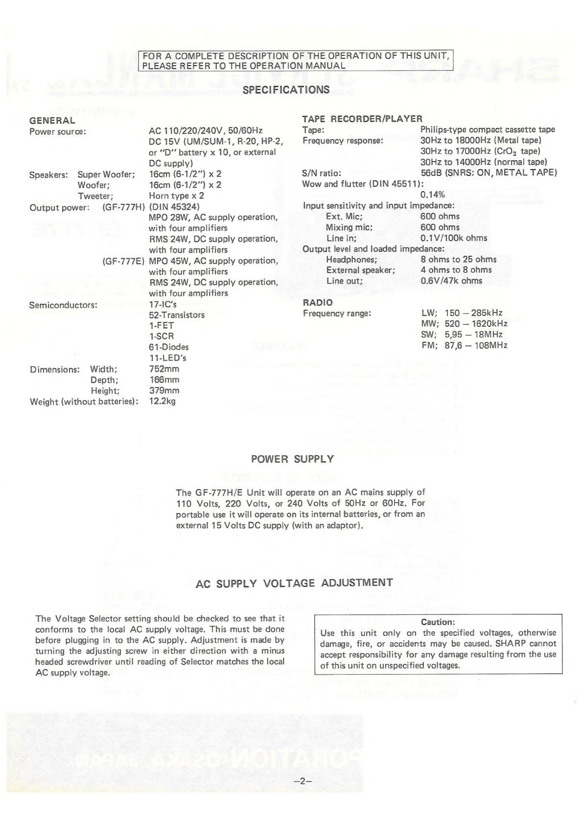
SPECIFIGATIONS,
qos
st
oe
cypress
EB
epee
coals
«ARR
6
gstet
R
amepegs
Cee
eee
see
eee
2
POWER
SUPPLY/AG-SUPPLY.
VOLTAGE.SELECTOR,
wo:.:0.00
ctecesegure
cence
w
canes
2
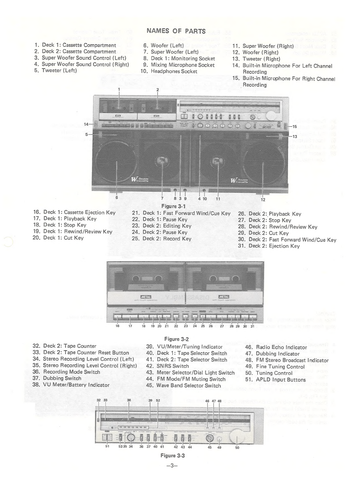
NAMES
OF
PARTS
a
isdseercveSpeiocoyeptasicss)
oy
tyecaj
can
Rhee
dceelshces
Se
Spneysbaqnpe
wien
decd
Spader
3,4
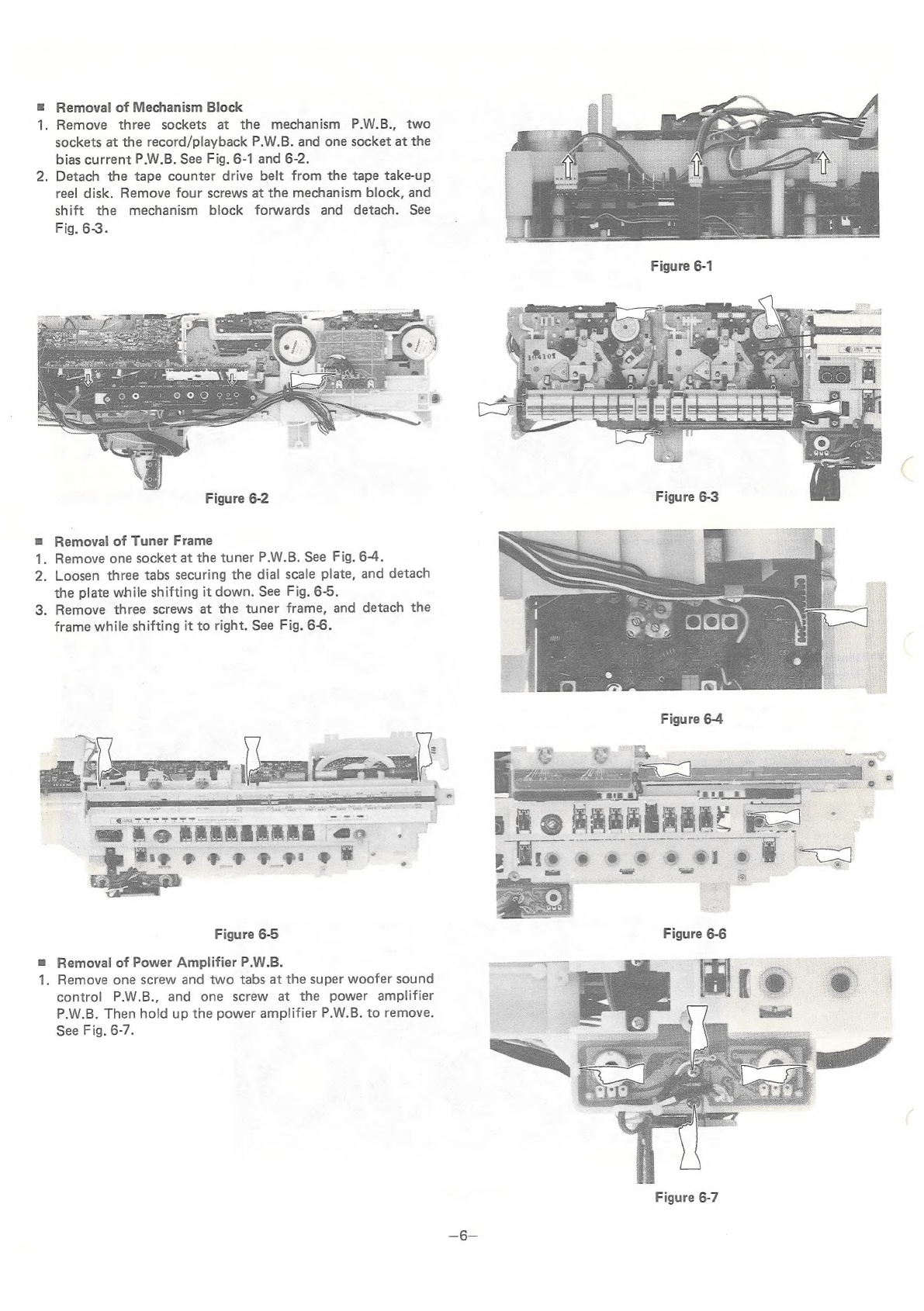
DISASSEMBLY
........
1G
Dien
Ot
Bmaeta
Kae
Cm
oeghs
se
We
Te
Dee
elame
ee
4~7
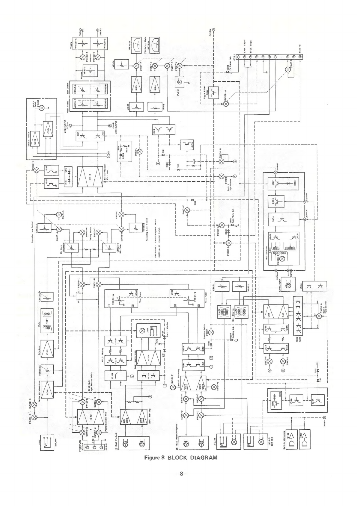
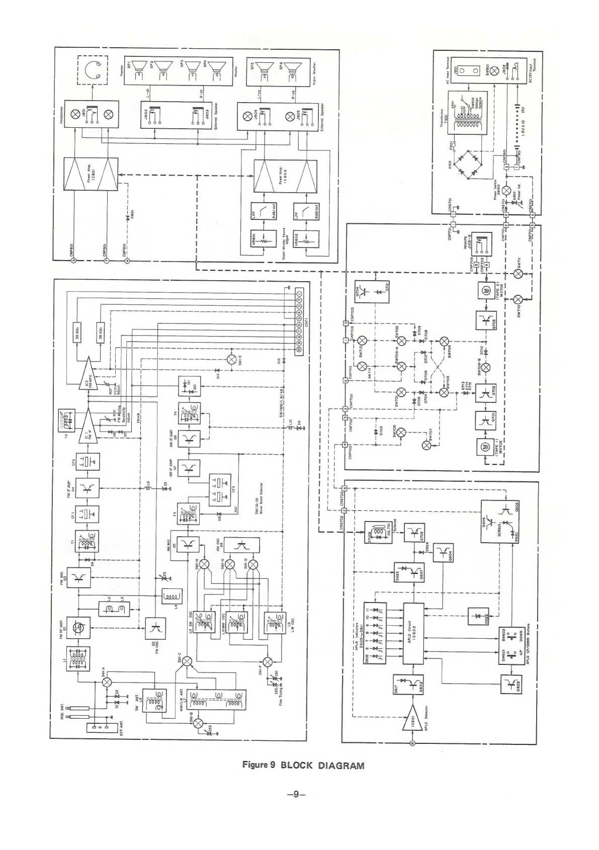
BLOCK.
DIAGRAM.
a
c.cccseccsberamesremeannn
cewenceuot
ee
weuaseoaguines
8,9
MECHANICAL.
ADJUSTMENT
sacncacce
cia
caae
cee
cane
e
cn
deen
ene
nee
ns
10
ELECTRICAL
ADJUSTMENT
oc
cccacccsedandaden
ines
wee
eneeeedaae
a
11
~16
NOTES
ON
SCHEMATIC:
DIAGRAM,
2.
ooo:
20s
ciuiaeeanae
cameee
maamerdmanc
aware
17
SERVICING
OF
LEG-LESS
TYPE
RESISTORS
AND
CAPACITORS
.........
17,18
SCHEMATIC
DIAGRAM)
«.c5sc0ica.eeswevis
vieeee
ee
Getions
ees
19,
20,
23,
24
WIRING
SIDE
OF
PRINTED
WIRING
BOARD
..................
21,22,25
~29
CABINET
EXPLODED
VIEW
ca.
.000
0
0tihate
teener.
Sasserln.
me
Laaosio
cael
30
~
32
MECHANISM
EXPLODED:
TOP
VIEW
...
..e¢cin
oc.
teu
aide
wagation
«.aeum
Dee
ds
33
MECHANISM
EXPLODED
BUTTOM
VIEW
*.
aiiceccs
deaiwen
Oo
setae
se
aarties
34
DIAL
CORDS
TRINGING
ic
ajsccise
tes
a:
0
se
a:
PROMS
cin,
SEES
AOR,
IE
ses
Ole
CNS
35
AG
SUPPLY:
CORID)
aco:
cctnsy-r
steps:
appeal
oa wo
OOS:
AAS
PENNS
wei".
te
oaibecs
lta
35
EQUIVALENT
CIRCUIT
OF
INTEGRATED
CIRCUIT
....................
36,
37
PACKING
METHOD
(GE-777E
Only)
ose:
ccniseewennees
snceeeeobe
wd
ee:
oak
38
REPLACEMENT
PARTS:
LIST
weiss
nace
sescyey
eect
sa
sea
oaunate
emi
erage
os
win
39
~
Back
SHARP
CORPORATION
Osaka,
JAPAN
GF-777H


 User manual")