Sharp CD-BA250H User manual

– 1 –
CD-BA250H/CD-BA2600H
No. S4126CDBA250H
CONTENTS Page
SAFETY PRECAUTION FOR SERVICE MANUAL ...........................................................................................................2
IMPORTANT SERVICE NOTES (CD-BA250H FOR U.K. ONLY) ..................................................................................... 3
SPECIFICATIONS ............................................................................................................................................................. 3
NAMES OF PARTS ........................................................................................................................................................... 4
OPERATION MANUAL ...................................................................................................................................................... 6
DISASSEMBLY................................................................................................................................................................ 11
REMOVING AND REINSTALLING THE MAIN PARTS................................................................................................... 14
ADJUSTMENT ................................................................................................................................................................. 15
BLOCK DIAGRAM ........................................................................................................................................................... 19
SCHEMATIC DIAGRAM / WIRING SIDE OF P.W.BOARD..............................................................................................22
VOLTAGE ........................................................................................................................................................................ 38
NOTES ON SCHEMATIC DIAGRAM .............................................................................................................................. 39
TYPES OF TRANSISTOR AND LED................................................................................................................................39
WAVEFORMS OF CD CIRCUIT...................................................................................................................................... 40
TROUBLESHOOTING ..................................................................................................................................................... 41
FUNCTION TABLE OF IC................................................................................................................................................ 45
FL DISPLAY......................................................................................................................................................................51
WIRING OF PRIMARILY SUPPLY LEADS (CD-BA250H FOR U.K. ONLY)....................................................................52
REPLACEMENT PARTS LIST/EXPLODED VIEW
PACKING METHOD (CD-BA250H FOR U.K. ONLY)
• In the interests of user-safety the set should be restored to its
original condition and only parts identical to those specified be
used.
SERVICE MANUAL
This document has been published to be used
for after sales service only.
The contents are subject to change without notice.
SHARP CORPORATION
MINI COMPONENT SYSTEM
MODEL CD-BA250H
CD-BA250H Mini Component System consisting of
CD-BA250H(mainunit) andCP-BA250H(speaker system).
MINI COMPONENT SYSTEM
MODEL CD-BA2600H
CD-BA2600H Mini Component System consisting of
CD-BA2600H(mainunit)and CP-BA2600H (speakersystem).
• Note for users in U.K.
Recording and playback of any material may require consent
which SHARP is unable to give. Please refer particularly to the
provisions of Copyright Act 1956, the Dramatic and Musical
Performers Protection Act 1956, the Performers Protection Acts
1963 and 1972 and to any subsequent statutory enactments and
orders.
RTV servis Horvat
Tel: ++385-31-856-842
Tel/fax: ++385-31-856-139
Mob: 098-788-319
www.rtv-horvat-d .hr
All manuals and user guides at all-guides.com
all-guides.com

CD-BA250H/CD-BA2600H
– 2 –
SAFETY PRECAUTION FOR
SERVICE MANUAL
Precaution to be taken when replacing and servicing the
Laser Pickup.
The AEL (Accessible Emission Level) of Laser Power Output
for this model is specified to be lower than Class 1
Requirements. However, the following precautions must be
observedduringservicingtoprotectyoureyesagainstexposure
to the Laser beam.
(1) When the cabinet has been removed, the power is turned
on without a compact disc, and the Pickup is on a position
outerthanthelead-inposition,theLaserwilllightforseveral
seconds to detect a disc. Do not look into the Pickup Lens.
(2) The Laser Power Output of the Pickup inside the unit and
replacementservicepartshavealreadybeenadjustedprior
to shipping.
(3) No adjustment to the Laser Power should be attempted
when replacing or servicing the Pickup.
(4) Under no circumstances look directly into the Pickup Lens
at any time.
(5)CAUTION-Useofcontrolsoradjustments,orperformance
of procedures other than those specified herein may result
in hazardous radiation exposure.
Laser Diode Properties
Material: GaAIAs
Wavelength: 780 nm
Emission Duration: continuous
Laser Output: max. 0.6 mW
CAUTION-INVISIBLE LASER RADIATION WHEN OPEN. DO NOT STARE INTO
BEAM OR VIEW DIRECTLY WITH OPTICAL INSTRUMENTS.
VARNING-OSYNLIG LASERSTRALNING NAR DENNA DEL AR OPPNAD. STIRRA
EJ IN I STRALEN OCH BETRAKTA EJ STRALEN MED OPTISKA INSTRUMENT.
ADVERSEL-USYNLIG LASERSTRALING VED ABNING. SE IKKE IND I
STRALEN-HELLER IKKE MED OPTISKE INSTRUMENTER.
VARO! AVATTAESSA OLET ALTTIINA NAKYMATON LASERSATEILYLLE.
ALA TUIJOTA SATEESEEN ALAKA KATSO SITA OPTISEN LAITTEEN LAPI.
VARNING-OSYNLIG LASERSTRALNING NAR DENNA DEL AR OPPNAD.
STIRRA EJ IN I STRALEN OCH BETRAKTA EJ STRALEN GENOM OPTISKT
INSTRUMENT.
ADVERSEL-USYNLIG LASERSTRALING NAR DEKSEL APNES. STIRR IKKE
INN I STRALEN ELLER SE DIREKTE MED OPTISKE INSTRUMENTER.
VAROITUS! LAITTEEN KÄYTTÄMINEN MUULLA KUIN TÄSSÄ
KÄYTTÖOHJEESSA MAINITULLA TAVALLA SAATTAA ALTISTAA
KÄYTTÄJÄN TURVALLISUUSLUOKAN 1
YLITTÄVÄLLENÄKYMÄTTÖMÄLLE
LASERSÄTEILYLLE.
VARNING - OM APPARATEN ANVÄNDS PÅ ANNAT SÄTT ÄN I DENNA
BRUKSANVISNING SPECIFICERAS. KAN ANVÄNDAREN UTSÄTTAS FÖR
OSYNLIG LASERSTRÅLNING, SOM ÖVERSKRIDER GRÄNSEN FÖR
LASERKLASS 1.
(CD-BA250H for U.K. only) (Except for U.K.)
All manuals and user guides at all-guides.com

– 3 –
CD-BA250H/CD-BA2600H
General
Amplifier (Except for U.K.)
CD player
Tuner
Cassette deck (Except for U.K.)
Power source AC 230 V, 50 Hz
Power consumption Power on: 124 W
Power stand-by: 0.6 W (*)
Dimensions Width: 270 mm (10-5/8")
Height: 330 mm (13")
Depth: 340 mm (13-3/8")
Weight 6.7 kg (14.7 lbs.)
( * ) This power consumption value is obtained when the demonstration mode is
cancelled in the power stand-by mode. cancel the demonstration mode.
Output power PMPO: 480 W
MPO: 240 W (120 W + 120 W) (DIN 45 324)
RMS: 150 W (75 W + 75 W) (DIN 45 324)
RMS: 104 W (52 W + 52 W) (DIN 45 500)
Output terminals Speakers: 6 ohms
Headphones: 16 - 50 ohms (recommended: 32 ohms)
Input terminals Video/Auxiliary (audio signal): 500 mV/47 kohms
Type 3-disc multi-play compact disc player
Signal readout Non-contact, 3-beam semiconductor laser pickup
D/A converter 1-bit D/A converter
Frequency response 20 - 20,000 Hz
Dynamic range 90 dB (1 kHz)
Frequency range FM: 87.5 - 108 MHz
AM: 522 - 1,620 kHz
Frequency response 50 - 14,000 Hz (Normal tape)
Signal/noise ratio 55 dB (TAPE 1, playback)
50 dB (TAPE 2, recording/playback)
Wow and flutter 0.35 % (DIN 45 511)
Type 2-way type speaker system
5 cm (2") Tweeter
13 cm (5-1/4") Woofer
Maximum input power 150 W
Rated input power 75 W
Impedance 6 ohms
Dimensions Width: 220 mm (8-11/16")
Height: 330 mm (13")
Depth: 217 mm (8-9/16")
Weight 3.0 kg (6.6 lbs.)/each
Amplifier (CD-BA250H for U.K.)
Cassette deck (CD-BA250H for U.K.)
Output power RMS: 150 W (75 W + 75 W) (10 % T.H.D.)
RMS: 104 W (52 W + 52 W) (0.9 % T.H.D.)
Output terminals Speakers: 6 ohms
Headphones: 16 - 50 ohms (recommended: 32 ohms)
Input terminals Video/Auxiliary (audio signal): 500 mV/47 kohms
Frequency response 50 - 14,000 Hz (Normal tape)
Signal/noise ratio 55 dB (TAPE 1, playback)
50 dB (TAPE 2, recording/playback)
Wow and flutter 0.3 % (WRMS)
SPECIFICATIONS
CD-BA250H/CD-BA2600H
IMPORTANT SERVICE NOTES (CD-BA250H FOR U.K. ONLY)
Beforereturningtheunittothecustomeraftercompletionofa
repairor adjustmentit isnecessaryforthefollowing withstand
voltage test to be applied to ensure the unit is safe for the
customer to use.
Setting of Withstanding Voltage Tester and set.
Set name set value
Withstanding Voltage Tester
Test voltage 4,240 VPEAK
3,000 VRMS
Set time 6 secs
Set current (Cutoff current) 4 mA
Unit
Judgment
OK: The “GOOD” lamp lights.
NG: The “NG” lamp lights and the buzzer sounds.
SHORT-CIRCUIT
AC POWER
SUPPLY CORD
CONNECT THE PROBE
TO GND OF CHASSIS
SCREW
PROBE
AC
UNIT
WITHSTANDING
VOLTAGE TESTER
+
-
OUT
CHASSIS SCREW
CP-BA250H/CP-BA2600H
Specifications for this model are subject to change without
prior notice.
All manuals and user guides at all-guides.com

CD-BA250H/CD-BA2600H
– 4 –
NAMES OF PARTS
CD-BA250H/CD-BA2600H
Front panel
1. Disc Tray
2. Timer Set Indicator
3. On/Stand-by Button
4. Tape 2 Cassette Compartment
5. Tape 1 Cassette Compartment
6. Equalizer Mode Select Button
7. Volume Up and Down Buttons
8. Extra Bass/Demo Mode Button
9. Disc Tray Open/Close Button
10. Disc Skip Button
11. Tuning and Time Up Button
12. CD or Tape Stop Button
13. CD Button
14. RDS Programme Type/Traffic Information Search Button
15. RDS EON Button
16. RDS ASPM (Auto Station Programme Memory) Button
17. Dimmer Button
18. Clock Button
19. Timer/Sleep Button
20. Headphone Socket
21. RDS Display Mode Selector Button
22. Video/Auxiliary Button
23. Tape (1 2) Button
24. Tuner (Band) Button
25. CD Play or Repeat, Tape Play Button
26. CD Track Up or Fast Forward, Tape 2 Fast Forward,
Tuner Preset Up Button
27. Tuning and Time Down Button
28. Memory/Set Button
29. Tape 2 Record Pause Button
30. CD Track Down or Fast Reverse, Tape 2 Rewind,
Tuner Preset Down Button
4
5
67
1
2
3
89
10
17
25
23
24
22
21
161514
131211
27 28 29 30 26
18
19
20
Display
1. RDS Indicator
2. Programme Type Indicator
3. Traffic Announcement Indicator
4. Extra Bass Indicator
5. FM Stereo Mode Indicator
6. Traffic Information Indicator
7. Traffic Programme Indicator
8. CD Play Indicator
9. FM Stereo Receiving Indicator
10. Dynamic PTY Indicator
11. EON Indicator
12. CD Repeat Play Indicator
13. CD Pause Indicator
14. Disc Number Indicators
15. Timer Play Indicator
16. Timer Recording Indicator
17. Tape 2 Record Indicator
18. Memory Indicator
19. Tape Play Indicator
20. Sleep Indicator
21. Spectrum Analyser/Volume Level Indicator
4
57
6
123
9101112 13 17
21
21 21
1819 20
8
14
15
16
All manuals and user guides at all-guides.com

– 5 –
CD-BA250H/CD-BA2600H
Rear panel
1. FM 75 Ohms Aerial Sock
2. AM Loop Aerial Socket
3. Video/Auxiliary (Audio Signal) Input Sockets
4. Speaker Terminals
5. AC Power Lead
2
1
3
4
5
Remote control
1. Remote Control Transmitter
2. Disc Number Select Buttons
3. CD Pause Button
4. CD Memory Button
5. CD Track Down or Fast Reverse Button
6. CD Clear Button
7. Tape 1 Play Button
8. Tape 1/Tape 2 Stop Button
9. Equalizer Mode Select Button
10. Tape 2 Record Pause Button
11. CD Button
12. Tuner (Band) Button
13. On/Stand-by Button
14. Extra Bass Button
15. CD Stop Button
16. CD Play or Repeat Button
17. CD Track Up or Fast Forward Button
18. CD Random Button
19. Tuner Preset Up and Down Buttons
20. Tape 2 Play Button
21. Tape 2 Rewind Button
22. Tape 2 Fast Forward Button
23. Video/Auxiliary Button
24. Tape (1
25. Volume Up and Down Buttons
1
215
16
17
18
19
20
21
24
3
6
4
7
8
9
10
14
13
12
11
5
25
22
23
Buttons with " " mark in the illustration can be operated on the remote control
only.
Other buttons can be operated both on the main unit and the remote control.
2) Button
All manuals and user guides at all-guides.com

CD-BA250H/CD-BA2600H
– 6 –
OPERATION MANUAL
CP-BA250H/CP-BA2600H
Setting the Clock
In this example, the clock is set for the 24-hour (0:00) display.
Note:
The "CLOCK" or time will flash at the push of the CLOCK button when the AC power
supply is restored after a power failure or unplugging the unit.
Readjust the clock as follows.
To readjust the clock:
Perform "Setting the Clock" from the beginning. If the time display is flashing, step 3
(for selecting the 24-hour or 12-hour display) will be skipped.
To change the 24-hour or 12-hour display:
1
Press the ON/STAND-BY button to turn the power on.
2
Press the CLOCK button and within 5 seconds, press the MEMO-
RY/SET button.
3
Press the TUNING/TIME ( or ) button to select 24-hour or 12-
hour display and then press the MEMORY/SET button.
"0:00" The 24-hour display will appear.
(0:00 - 23:59)
"AM 12:00" The 12-hour display will appear.
(AM 12:00 - PM 11:59)
"AM 0:00" The 12-hour display will appear.
(AM 0:00 - PM 11:59)
Note that this can only be set when the unit is first installed or it has been reset.
(Refer to step 3 under "If trouble occurs")
4
Press the TUNING/TIME ( or ) button to adjust the hour and then
press the MEMORY/SET button.
Press the TUNING/TIME ( or ) button once to advance the time by 1 hour.
Holdit down to advance continuously.
When the 12-hour display is selected, "AM" will change automatically to "PM".
5
Press the TUNING/TIME ( or ) button to adjust the minutes and
then press the MEMORY/SET button.
Press the TUNING/TIME ( or ) button once to advance the time by 1
minute. Hold it down to change the time in 5-minute intervals.
The hour will not advance even if minutes advance from "59" to "00".
The clock begins counting from "0" seconds. (Seconds are not displayed.)
The time display will disappear after a few seconds.
To confirm the time display:
Press the CLOCK button.
The time display will appear for about 5 seconds.
1 Clear all the programmed contents. [Perform to step 3 under "If trouble occurs"
2 Perform "Setting the Clock" from the beginning.
Speaker system
1. Tweeter
2. Woofer
3. Bass Reflex Duct
4. Speaker Wire
3
4
1
2
3
All manuals and user guides at all-guides.com
all-guides.com

– 7 –
CD-BA250H/CD-BA2600H
Remote Control
Test of the remote control
Face the remote control directly to the remote sensor on the unit.
The remote control can be used within the range shown below:
Press the ON/STAND-BY button. Does the power turn on? Now, you can enjoy the
music.
0.2 m - 6 m
(8" - 20')
Remote sensor
Troubleshooting Chart
Many potential "problems" can be resolved by the owner without calling a service
technician.
If something is wrong with this product, check the following before calling your author-
ised SHARP dealer or service centre.
General
CD player
Tuner
Cassette deck
Remote control
Condensation
Symptom Possible cause
The clock is not on time. Did a power failure occur? Reset the
clock.
When a button is pressed, the unit
does not respond. Set this unit to the power stand-by mode
and then turn it back on.
Ifthe unit still malfunctions, reset it. Refer
to step 3 under "If trouble occurs"
No sound is heard. Is the volume level set to "0"?
Are the headphones connected?
Are the speaker wires disconnected?
Symptom Possible cause
Playback does not start. Is the disc loaded upside down?
Playback stops in the middle or is
not performed properly. Does the disc satisfy the standards?
Is the disc distorted or scratched?
Playback sounds are skipped, or
stopped in the middle of a track. Is the unit located near excessive vibra-
tions?
Is the disc very dirty?
Has condensation formed inside the unit?
Symptom Possible cause
Radio makes unusual noise con-
secutively. Is the unit placed near the TV or compu-
ter?
Is the FM aerial or AM loop aerial placed
properly? Move the AC power lead away
from the aerial if located near.
Symptom Possible cause
Cannot record. Is the erase-prevention tab removed?
Cannot record tracks with proper
sound quality. Is it a normal tape? (You cannot record on
ametal or CrO tape.)
Cannot erase completely.
Sound skipping. Is there any slack?
Is the tape stretched?
Cannot hear treble. Are the capstans, pinch rollers, or heads
dirty?
Sound fluctuation.
Cannot remove the tape. If a power failure occurs during playback,
the heads remain engaged with the tape.
Do not open the compartment forcibly.
Wait until electricity resumes.
Symptom Possible cause
The remote control does not oper-
ate. Is the AC power lead of the unit plugged
in?
Is the battery polarity respected?
Are the batteries dead?
Is the distance or angle incorrect?
Does the remote control sensor receive
strong light?
Sudden temperature changes, storage or opera-
tion in an extremely humid environment may
cause condensation inside the cabinet (CD pick-
up, tape heads, etc.) or on the transmitter on the
remote control.
Condensation can cause the unit to malfunction.
If this happens, leave the power on with no disc
(or cassette) in the unit until normal playback is
possible (about 1 hour). Wipe off any condensa-
tion on the transmitter with a soft cloth before op-
erating the unit.
Troubleshooting Chart
If trouble occurs
When this product is subjected to strong external interference (mechanical shock,
excessive static electricity, abnormal supply voltage due to lightning, etc.) or if it is
operated incorrectly, it may malfunction.
If such a problem occurs, do the following:
Caution:
This operation will erase all data stored in memory including clock, timer settings,
tuner preset, and CD programme.
Before transporting the unit
1 Set the unit to the stand-by mode and turn the power on again.
2 If the unit is not restored in step 1, unplug and plug in the unit, and then turn
the power on.
3 If neither step 1 nor 2 restores the unit, do the following:
Press the ON/STAND-BY button to enter the power stand-by mode.
Whilst pressing down the / button and the X-BASS/DEMO button, press
the ON/STAND-BY button until "CLEAR AL" appears.
1 Press the ON/STAND-BY button to turn the power on.
2 Press the CD button.
3 Press the OPEN/CLOSE button to open the disc tray.
Remove all CDs inserted in the unit.
4 Press the OPEN/CLOSE button to close the disc tray.
Make sure that "NO DISC" is displayed.
5 Pressthe ON/STAND-BY button to enter the stand-by mode, and then unplug
the AC power lead from the AC socket.
All manuals and user guides at all-guides.com

CD-BA250H/CD-BA2600H
– 8 –
Accessories
123
Battery installation of remote control
Use 2 “AA” size batteries (UM/SUM-3, R6, HP-7 or similar). Batteries are not included.
Remove the
Insert the batteries
Replace the cover.
battery cover.
as shown.
1
2
2
FM antenna × 1
Remote control× 1AM loop antenna× 1
System connections
3
3
AM loop antenna
FM antenna
Red Black
Right speaker
Left speaker
Wall socket
(AC 230 V, 50 Hz)
(For U. K.)
Wall socket
(AC 230 V, 50 Hz)
(Except for U. K.)
Right speaker Left speaker
RCA lead
(not supplied)
To the line
output sockets VCR, DVD, etc.
TV
All manuals and user guides at all-guides.com

– 9 –
CD-BA250H/CD-BA2600H
Turn on your system
4
4
12
The first time the unit is plugged,
the unit will enter the demonstra-
tion mode. You will see words
scroll.
Press the
X-BASS/DEMO button
to cancel the demon-
stration mode.
Press the ON/
STAND-BY button to
turn the power on.
1
Press the CD button.
2
Press the OPEN/CLOSE button to
open the disc tray.
3
Place the CD(s) on the disc tray, label
side up.
When loading a third disc, press the
DISC SKIP button to turn the disc tray,
then place the CD in the open position.
4
Press the OPEN/CLOSE button to
close the disc tray.
5
To select the CD you want to listen to
first, press one of 1 - 3 buttons on
the remote control.
6
Press the button to start playback.
12 cm (5”)
8 cm (3”)
Listening to a CD (CDs)
FM stereo mode indicator
FM stereo receiving indicator
1
Press the TUNER (BAND) button repeat-
edly to select the desired frequency
band (FM or AM).
2
Press the TUNING/TIME ( or ) but-
ton to tune in to the desired station.
When the TUNING/TIME button is
pressedfor more than 0.5 seconds, scan-
ningwill start automatically and the tuner
will stop at the first receivable broadcast
station.
To receive an FM stereo transmission:
Press the TUNER (BAND) button to display the
“ST” indicator.
●“ ” will appear when an FM broadcast is in ste-
reo.
Listening to the radio
■If trouble occurs
When this product is subjected to strong external interference
(mechanical shock, excessive static electricity, abnormal sup-
ply voltage due to lightning, etc.) or if it is operated incorrectly, it
may malfunction.
If such a problem occurs, do the following:
1. Set the unit to the stand-by mode and turn the power
on again.
2.
If the unit is not restored in step 1, unplug and plug in
the unit, and then turn the power on.
3.
If neither step 1 nor 2 restores the unit, do the follow-
ing:
Press the ON/STAND-BY button to enter the power
stand-by mode.
Whilst pressing down the button and the X-BASS/
DEMO button, press the ON/STAND-BY button until
“CLEAR AL” appears.
■Maintenance
●Dirty heads, capstans or pinch rollers can cause poor
sound and tape jams. Clean these parts with a cotton swab
moistened with commercial head/pinch roller cleaner or
isopropyl alcohol.
●When cleaning the heads, pinch rollers, etc., unplug the
unit which contains high voltages.
●After long use, the deck’s heads and capstans may be-
come magnetised, causing poor sound. Demagenetise
these parts once every 30 hours of playing/recording time
by using a commercial tape head demagnetiser. Read the
demagnetiser’s instructions carefully before use.
●Clean the dust or stain on the CD pickup lens using a com-
mercial cleaning disc (brush type).
1Open the cassette door by pushing the
area marked “ PUSH EJECT”.
2Load a cassette into the TAPE 1 or TAPE
2 cassette compartment with the side to
be played facing toward you.
3Press the TAPE (1 2) button to select
the cassette you want to listen to.
4Press the button to start playback.
TAPE 1 TAPE 2
Listening to a cassette tape (TAPE 1 or TAPE 2)
TAPE 1
TAPE 2
AC
C
DE
B
B
A Playback head
B Capstan
D Erase head
E Recording/Playback head
C Pinch roller
➀
➁
All manuals and user guides at all-guides.com

CD-BA250H/CD-BA2600H
– 10 –
Descriptions of the PTY (Programme Type) codes, TP (Traffic Programme) and
TA (Traffic Announcement).
You can search for and receive the following PTY, TP and TA signals.
Note:
When you select a programme in the EON stand-by mode, the unit will display "TI"
instead of "TA".
NEWS Short accounts of facts, events and publicly expressed views, reportage
and actuality.
AFFAIRS Topical programme expanding or enlarging upon the news, generally in
different presentation style or concept, including debate, or analysis.
INFO Programmes whose purpose is to impart advice in the widest sense.
SPORT Programme concerned with any aspect of sport.
EDUCATE Programme intended primarily to educate, of which the formal ele-
ment is fundamental.
DRAMA All radio plays and serials.
CULTURE Programmes concerned with any aspect of national or regional cul-
ture, including language, theatre, etc.
SCIENCE Programmes about the natural sciences and technology.
VARIED Used for mainly speech-based programmes usually of light-entertain-
ment nature, not covered by other categories. Examples include:
quizzes, panel games, personality interviews.
POP M Commercial music, which would generally be considered to be of cur-
rent popular appeal, often featuring in current or recent record sales
charts.
ROCK M Contemporary modern music, usually written and performed by
young musicians.
EASY M Current contemporary music considered to be "easy-listening", as op-
posed to Pop, Rock or Classical, or one of the specialised music
styles, Jazz, Folk or Country. Music in this category is often but not
always, vocal, and usually of short duration.
LIGHT M Classical music for general, rather than specialist appreciation. Ex-
amples of music in this category are instrumental music, and vocal or
choral works.
CLASSICS Performances of major orchestral works, symphonies, chamber mu-
sic, etc., and including Grand Opera.
OTHER M Musical styles not fitting into any of the other categories. Particularly
used for specialist music of which Rhythm & Blues and Reggae are
examples.
WEATHER Weather reports and forecasts and meteorological information.
FINANCE Stock Market reports, commerce, trading, etc.
CHILDREN For programmes targeted at a young audience, primarily for entertain-
ment and interest, rather than where the objective is to educate.
SOCIAL Programmesabout peopleand things that influence them individually
or in groups. Includes: sociology, history, geography, psychology and
society.
RELIGION Any aspect of beliefs and faiths, involving a God or Gods, the nature
of existence and ethics.
PHONE IN Involving members of the public expressing their views either by
phone or at a public forum.
TRAVEL Features and programmes concerned with travel to near and far des-
tinations, package tours and travel ideas and opportunities. Not for
use for announcements about problems, delays, or roadworks affect-
ing immediate travel where TP/TA should be used.
LEISURE Programmes concerned with recreational activities in which the listen-
er might participate. Examples include, Gardening, Fishing, Antique
collecting, Cooking, Food & Wine, etc.
JAZZ Polyphonic, syncopated music characterised by improvisation.
COUNTRY Songs which originate from, or continue the musical tradition of the
American Southern States. Characterised by a straightforward melo-
dy and narrative story line.
NATION M Current Popular Music of the Nation or Region in that country's lan-
guage, as opposed to International 'Pop' which is usually US or UK
inspired and in English.
OLDIES Music from the so-called "golden age" of popular music.
FOLK M Music which has its roots in the musical culture of a particular nation,
usually played on acoustic instruments. The narrative or story may be
based on historical events or people.
DOCU-
MENT Programme concerned with factual matters, presented in an investi-
gative style.
TEST Broadcast when testing emergency broadcast equipment or receiv-
ers.
ALARM ! Emergencyannouncement madeunderexceptionalcircumstancesto
give warning of events causing danger of a general nature.
NONE No programme type (receive only).
TP Broadcasts which carry traffic announcements.
TA Traffic announcements are being broadcast.
Using the Radio Data System (RDS)
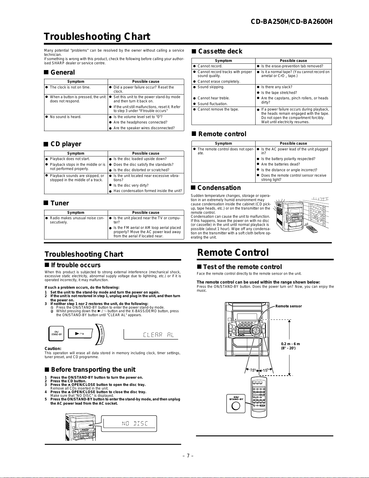
RDS is a broadcasting service which a growing number of FM stations provide.
These FM stations send additional signals along with their regular programme
signals. They send their station names, and information about the type of pro-
gramme such as sports or music, etc.
When tuned to an RDS station, "RDS" and the station name will be displayed.
"TP" (Traffic Programme) will appear on the display when the received broadcast car-
ries traffic information, and "TA" (Traffic Announcement) will appear whilst a traffic
information is on air.
"EON" will appear whilst the EON (Enhanced Other Networks information) data is
broadcast.
"PTYI" (Dynamic PTY Indicator) will appear whilst the Dynamic PTY station is
received.
"RT" (Radio Text) will appear whilst the unit receives the Radio text data.
"CT" (Clock Time) will appear whilst the unit receives the RDS CT data.
You can control the RDS by using the buttons on the main unit only.
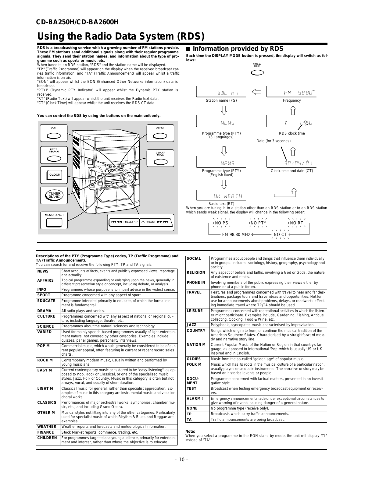
Information provided by RDS
Each time the DISPLAY MODE button is pressed, the display will switch as fol-
lows:
When you are tuning in to a station other than an RDS station or to an RDS station
which sends weak signal, the display will change in the following order:
Station name (PS) Frequency
Programme type (PTY) RDS clock time
(8 Languages)
Date (for 3 seconds)
Programme type (PTY) Clock-time and date (CT)
(English fixed)
Radio text (RT)
NO PS NO PTY
FM 98.80 MHz NO CT
NO RT
All manuals and user guides at all-guides.com

– 11 –
CD-BA250H/CD-BA2600H
1 Top Cabinet 1. Screw ...................... (A1) x4 11-1
2 Side Panel 1. Screw ...................... (B1) x8 11-1
(Left/Right)
3 CD Player Unit/ 1. Turn on the power supply,.. 11-2
CD Tray Cover open the disc tray, take out
the CD tray cover, and close.
(Note 1)
2. Screw ...................... (C1) x1
3. Hook........................ (C2) x3
4. Hook........................ (C3) x2
5. Socket ..................... (C4) x2
4 Rear Panel with 1. Screw .................... (D1) x10 11-2
Fan Motor 2. Socket ..................... (D2) x1
5 Main PWB 1. Screw ...................... (E1) x3
11-2,12-2
2. Socket ..................... (E2) x3
3. Flat Cable ............... (E3) x1
4. Flat Wire.................. (E4) x1
6 Front Panel 1. Screw .......................(F1) x2 12-2
7 Display PWB 1. Screw ....................(G1) x12 12-3
2. Flat Cable ............... (G2) x1
8 Tape Mechanism 1. Open the cassette holder. .. 12-3
2. Screw...................... (H1) x5
9
Headphones PWB
1. Screw ....................... (J1) x1 12-3
10 Turntable 1. Hook........................ (K1) x2 12-4
2. Cover ...................... (K2) x1
11 Disc Tray 1.
Turn fully the lock lever in the
11-3
arrow direction
.
2.
While holding the lock lever,rotate
12-1
the cam gear until the cam gear
rib engages with the clamp lever.
3.
Push the slide chassis backward to
12-5
engage the claw with the groove
and remove it in the direction
of the arrow. ...............
(L1) x6
12 CD Servo PWB 1. Screw ......................(M1) x1 12-6
(Note 2) 2. Hook........................(M2) x2
3. Socket .....................(M3) x4
13 CD Mechanism 1. Hook........................ (N1) x2 13-1
2. Hook........................ (N2) x3
DISASSEMBLY
Caution on Disassembly
Follow the below-mentioned notes when disassembling
the unit and reassembling it, to keep it safe and ensure
excellent performance:
1. Take cassette tape and compact disc out of the unit.
2. Be sure to remove the power supply plug from the wall
outlet before starting to disassemble the unit.
3.Takeoffnylonbands or wire holders where they need to
beremovedwhendisassemblingtheunit.Afterservicing
theunit,besuretorearrangetheleads where they were
before disassembling.
4. Take sufficient care on static electricity of integrated
circuits and other circuits when servicing.
Figure 11-2
Figure 11-3
CD-BA250H/CD-BA2600H
STEP REMOVAL PROCEDURE FIGURE
Figure 11-1
CD-BA250H/CD-BA2600H
Note 1: How to open the changer manually. (Fig. 11-3)
1. In this state, turn fully the lock lever in the arrow direction through
the hole on the loading chassis bottom.
2.
While holding the lock lever, rotate the cam gear anticlockwise until the
cam gear rib engages with the clamp lever.
(Fig. 12-1)
3. After that, push forward the CD slide chassis.
Note 2:
1. After removing the connector for the optical pickup from the
connector,wraptheconductivealuminiumfoilaroundthefrontend
of the connector so as to protect the optical pickup from electro-
static damage.
Lock Lever
CD Player Unit
(Bottom View)
(B1) x 4
ø3 x 10mm (B1) x 2
ø3 x 10mm
Rear
Panel
(B1) x 2
ø3 x 10mm
Side Panel
(Right)
Side Panel
(Left)
(A1) x 2
ø3 x 12mm
(A1) x 2
ø3 x 12mm Top Cabinet
(E1) x 1
ø3 x 10mm
(C3) x 1
(D1) x 2
ø3 x 10mm
(D2) x 1
CD Player
Unit
CD Tray Cover
Pull
(C3) x 1
(C4) x 2 (C2) x 3
1
1
2
CD Servo
PWB
(C1) x 1
ø3 x 10mm
(D1) x 8
ø3 x 10mm
Rear
Panel
Main PWB
Lug Wire
Note 3:
1. Be careful not to break the claw of the CD mechanism.
2. When fining back the cam gear assembly, let it lock by front
movement.
All manuals and user guides at all-guides.com
all-guides.com

CD-BA250H/CD-BA2600H
– 12 –
Figure 12-1
Figure 12-2
Figure 12-3
Figure 12-4
Figure 12-5
Figure 12-6
Clamp Lever
CD Player Unit
(Top View)
Cam Gear Rib
Turntable
Slide
Chassis
(K2) x 1
CD Player Unit
(K1) x 2
1
3
2
(L1) x 3
(L1) x 3
Main PWB
Front Panel
Headphones
PWB
Transformer
PWB
Power PWB
(E2) x 2 (E4) x 1
(E3) x 1 (E2) x 1
(F1) x 2
ø3 x 8mm
(E1) x 2
ø3 x 10mm
(G2) x 1
(G1) x 12
ø3 x 10mm
(H1) x 5
ø3 x 10mm
Display PWB
Front Panel
Headphones
PWB
Open
Cassette
Holder
Tape
Mechanism
(J1) x 1
ø3 x 10mm
Lug Wire
(M3) x 2
(M2) x 2
(M3) x 2
CD Servo
PWB Slide
Chassis
(M1) x 1
ø3 x 8mm
All manuals and user guides at all-guides.com

– 13 –
CD-BA250H/CD-BA2600H
1 Front Panel 1. Net......................... (A1) x1 13-2
2 Woofer 1. Screw .................... (B1) x4 13-3
3 Tweeter 1. Screw .................... (C1) x2 13-3
STEP REMOVAL PROCEDURE FIGURE
Figure 13-2
Figure 13-1
CP-BA250H/CP-BA2600H
Figure 13-3
(N2) x 3
(N1) x 1 (N1) x 1
CD
Mechanism
(A1) x 1
Screwdriver
Driver should
be pried away
from Speaker Box.
Front Panel
Speaker Box
(B1) x 4
ø4 x 12mm
Woofer
(C1) x 2
ø3 x 10mm
Tweeter
All manuals and user guides at all-guides.com

CD-BA250H/CD-BA2600H
– 14 –
REMOVING AND REINSTALLING THE MAIN PARTS
TAPE MECHANISM SECTION
Perform steps 1 to 6 and 8 of the disassembly method to
remove the tape mechanism.
How to remove the record/playback and erase
heads (TAPE 2) (See Fig. 14-1)
1. When you remove the screws (A1) x 2 pcs., the recording/
playback head and three-dimensional head of the erasing
head can be removed.
How to remove the playback head (TAPE 1)
(See Fig. 14-2)
1. When you remove the screws (B1) x 2 pcs., the playback
head.
How to remove the pinch roller (TAPE 1/2)
(See Fig. 14-3)
1. Carefully bend the pinch roller pawl in the direction of the
arrow <A>, and remove the pinch roller (C1) x 1 pc., in the
direction of the arrow <B>.
Note:
When installing the pinch roller, pay attention to the spring
mounting position.
How to remove the belt (TAPE 2) (See Fig. 14-4)
1. Remove the main belt (D1) x 1 pc., from the motor side.
2. Remove the FF/REW belt (D2) x 1 pc.
How to remove the belt (TAPE 1) (See Fig. 14-4)
1. Remove the main belt (E1) x 1 pc., from the motor side.
2. Remove the FF/REW belt (E2) x 1 pc.
How to remove the motor (See Fig. 14-5)
1. Remove the screws (F1) x 2 pcs., to remove the motor.
Figure 14-1
Figure 14-2
Figure 14-3
Figure 14-4Figure 14-5
(A1) x 2
Ø2 x 9mm
TAPE 2
Record/Playback
Head
Erase Head
Clutch Ass'y
(B1) x 2
Ø2 x 9mm
TAPE 1
Playback
Head
Clutch Ass'y
Pinch Roller
(C1) x 1 <A>
<B>
Pinch
Roller
Pawl
Pull
(F1) x 2
Ø2.6 x 5 mm
Motor
Clutch Ass'y
TAPE 2 TAPE 1
Main Belt
(E1) x 1
TAPE 2
Main Belt
(D1) x 1
TAPE 1
Main Belt
(D1) x 1 Main Belt
(E1) x 1
FF/REW
Belt
(D2) x 1
FF/REW
Belt
(E2) x 1
Motor
Motor
All manuals and user guides at all-guides.com

– 15 –
CD-BA250H/CD-BA2600H
How to remove the pickup (See Fig. 15-2)
1. Remove the stop washer (B1) x 1 pc., to remove the gear
(B2) x 1 pc.
2.Removethe screws (B3) x 2 pcs., to remove the shaft (B4).
3. Remove the pickup.
Note
After removing the connector for the optical pickup from the
connectorwraptheconductivealuminiumfoilaroundthefront
end of connector so as to protect the optical pickup from
electrostatic damage.
Figure 15-2
CD MECHANISM SECTION
Perform steps 1, 2, 3, 10, 11, 12 and 13 of the disassembly
method to remove the CD mechanism.
How to remove the loading motor
(See Fig. 15-1)
1. Bend the hooks (A1) x 5 pcs., to remove the loading motor.
2. Remove the drive belt (A2) x 1pc.
Figure 15-1
ADJUSTMENT
MECHANISM SECTION
•Driving Force Check
Torque Meter Specified Value
Play: TW-2111 Tape 1: Over 80 g
Tape 2: Over 80 g
•Torque Check
Torque Meter
Tape 2
Play: TW-2111 30 to 80 g.cm 30 to 80 g.cm
Fast forward: TW-2231 — 70 to 180 g.cm
Rewind: TW-2231 — 70 to 180 g.cm
Specified Value
Tape 1
Specified
Value
Adjusting
Point Instrument
Connection
Test Tape
Normal MTT-111 Variable 3,000 ±30 Hz Speaker
speed Resistor in Terminal
motor. (Load
resistance:
6 ohms)
•Tape Speed
Figure 15-3
(A1) x 2
(A1) x 1
Loading
Motor
Loading
Motor PWB
Slide
Chassis
(A1) x 2
Pulley
Drive Belt
(A2) x 1
Loading
Motor
(B3) x 2
ø2.6 x 6mm
Shaft
(B4) x 1
Stop Washer
(B1) x 1
Gear
(B2) x 1
CD Mechanism
Pickup
TAPE MECHANISM
Tape
Motor
Variable Resistor in motor
All manuals and user guides at all-guides.com

CD-BA250H/CD-BA2600H
– 16 –
Test Stage Frequency Frequency
Display Setting/
Adjusting
Parts
Instrument
Connection
CD SECTION
• AM IF/RF
Signal generator: 400 Hz, 30%, AM modulated
*1. Input: Antenna Output: TP302
*2. Input: Antenna Output: TP301
TUNER SECTION
fL: Low-range frequency
fH: High-range frequency
AM IF 450 kHz 1,620 kHz T351 *1
AM Band — 522 kHz (fL): T306 *2
Coverage 1.1 ±0.1 V
AM Tracking 990 kHz 990 kHz (fL): T303 *1
Figure 16-1 ADJUSTMENT POINTS
Figure 16-2
CD ERROR CODE DESCRIPTION
Error State Code
[Servo System Error]
0001 Cannot detect Pickup-in SW
0002 DSP access error
[Error during close operation]
0101 Open/Close SW not functioning (Low →High)
0103 Open/Close SW not functioning (High →Low)
[Error during open operation]
0201 Open/Close SW not functioning (Low →High)
0203 Open/Close SW not functioning (High →Low)
[Error during skip operation]
0302 Pickup-in SW is not detected
0306 During Disc 1 search, Open/Close SW or Clamp SW
or Disc SW do not change to low.
0307 Clamp SW not function (Low →High)
0308 Clamp SW not function (High →Low)
Items adjusted automatically
(1)Offset adjustment (The offset voltage between the head
amplifier output and the VREF reference voltage is
compensated inside the IC.)
* Focus offset adjustment
* Tracking offset adjustment
(2) Tracking balance adjustment (waveform drawing
Fig.16-2 EFBL)
(3)Gainadjustment(Thegainiscompensatedinsidethe IC
sothattheloopgainatthegain crossover frequency will
be 0 dB.)
* Focus gain adjustment
* Tracking gain adjustment
•Adjustment
Since this CD system incorporates the following automatic
adjustment functions, readjustment is not needed when
replacingthepickup.Therefore,differentPWBsandpickups
can be combined freely.
Each time a disc is changed, these adjustments are
performed automatically. Therefore, playback of each disc
can be performed under optimum conditions.
FE301
AM IF
T303
T306
AM
TRACKING fL
AM BAND
COVERAGE fL
T351
MAIN PWB
CNP302
AM LOOP
ANTENNA
SO302
FM
ANTENNA
TP302
R357
R336
TP301
T
T
EFBL
FDO
TE
Stopped
CH1=500 mV
DC 10:1 CH2=200 mV
DC 10:1 CH3=1 V
DC 10:1 500 ms/div
(500 ms/div)
NORM:20 kS/s
1
2
3
=Record Length=
Smoothing : ON CH1 : 0.000 V
CH2 : 0.000 V Main : 100 K
Zoom : 2 k Mode : SINGLE
Type : EDGE CH1
Delay : 0.0 ns
Hold off : 0.2 µs
CH3 : 0.00 V
CH4 : 0.00 V
BW : FULL
=Trigger==Filter= =Offset=
CH2
v/DIV
200 mV
1999/04/05 20:26:47
• FM
Notes:
1: Description of the "FM IF Adjustment" is not carried on this
Manual. It is because the IF coil in the FM front end section
has been best adjusted in the factory so that its further
adjustment is not needed at the field. When replacing the
FM front end assembly, no adjustment is needed either.
2: The parts in the FM front end section are prepared in a
complete unit, so you can't obtain each part individually.
All manuals and user guides at all-guides.com
all-guides.com

– 17 –
CD-BA250H/CD-BA2600H
TEST MODE
•Setting the test mode
Any one of test mode can be set by pressing several keys as follows.
<X-BASS> + <CD> + <POWER> TEST:CD operation test.
Function:-CD test mode.
-Enter test mode.
C D T E S T
OPEN/CLOSE operation is using manual.
<< >>, << >> buttons make pick's slide possible.
Do TOC IL. Do normal play.
When these following key is input
into PLAY key, track number can
be appoint directly.
<<PLAY>> key input. <<MEMORY>> key input.
<< 1>> key: Track 4
<< 2>> key: Track 9
<< 3>> key: Track 15
<<STOP>> key input.
STOP
Laser ON.
<<MEMORY>> key input.
Tracking OFF play at that
specific point.
<<MEMORY>> key input.
Tracking ON play from
that specific point.
<<STOP>> key input.
STOP
IL isn't done.
VOL — Last memory.
BAL — CENTER
P.GEQ — FLAT
X-BASS — OFF
To cancel : Power OFF
Sliding the PICKUP with
<< >>, <<
>> button
must only be in STOP mode.
<<MEMORY>>
key input.
Adjustment result
automatically will
display as below
for each 2 sec :
a) "FOFF_XX"
b) "TOFF_XX"
c) "TBAL_XX"
d) "TGAN_XX"
f) "FGAN_XX"
g) "RFLS_XX"
explanation:
a) Focus off set. ="FOFF_XX"
b) Tracking off set. ="TOFF_XX"
c) Tracking balance. ="TBAL_XX"
d) Tracking gain. ="TGAN_XX"
f) Focus Gain. ="FGAN_XX"
g) RF level shift. ="RFLS_XX"
Adjustment result auto-
matically will display as
below.
for each 2 sec :
a) "FOFF_XX"
b) "TOFF_XX"
c) "TBAL_XX"
d) "TGAN_XX"
f) "FGAN_XX"
g) "RFLS_XX"
XX: Hex value.
All manuals and user guides at all-guides.com

CD-BA250H/CD-BA2600H
– 18 –
Standard Specification of Stereo System Error Message Display Contents
Error Contents DISPLAY Notes
Output while Device Protection Operation. 'PROTECT' 00: While in Protect Circuit Operate.
01: Over Current Detection.
02: DC Detection.
03:
TAPE Mechanism Error. 'ER-TA**' 00: Tape Mechanism Error.
01: Initial Error.
02:
03:
CD/VCD Pickup Mechanism Error. 'ER-CD**' 00: Pickup Mechanism Error.
01: PU-IN SW Detection NG.
02:
03:
04:
CD Changer Mechanism Error. 'ER-CD**' 10: Changer Error.
11: Initial Error.
12:
13:
Tray Error. 'ET-CD**' 20: Tray Error.
21:
22:
23:
Focus Not Match. 'NO DISC'
IL Time Over. 'NOT READ'
TUN PLL Unlock. 'ER-TU**' 00: TUN Error.
01: PLL Unlock.
02:
03:
All manuals and user guides at all-guides.com

– 19 –
CD-BA250H/CD-BA2600H
Figure 19 BLOCK DIAGRAM (1/3)
+5V
CNS4 BI4
CNP4
M3
T/T UP DOWN
LOADING
+3.3V
TO DISPLAY SECTION
TO MAIN SECTION
CONSTANT
VOLTAGE
Q2
LASER
DRIVER
+3.3V
Q1
+5V
PICK UP UNIT
IC1
LC78645E
CD SERVO
VVDD
LDD
LDS
M
SW3
DISC
NUMBER
SW2
CLAMP
SW1
OPEN/
CLOSE
CNP8
CNP7
TRACKING COIL
FOCUS COIL
SW4
PICKUP
IN
M2
SLED
MOTOR
M1
SPINDLE
MOTOR
M
M
R-CH
Q3
XVDD
RVDD
LVDD
ADAVDD
RFVDD
XL1
33.8688 MHz
OC. DISC NO
CLAMP SW
CD RES
CLK
DI
DO
CE
DRF
WRQ
+B6(+5V)
+B6(+5V)
DGND
L-CH
AGND
VCC3
VCC2
VCC4
VCC1
IC2
M63001FP
FOCUS/TRACKING/
SPIN/SLED
DRIVER
XIN
XOUT
RES
WRQ
DO
DI
CLK
CE
TIN2
TIN1
FIN2
FIN1
TD0
FD0
SPDO
SLDO
CONT5
CONT2
CONT3
CONT4
RCHO
RVSS
LVSS
LCHO
80
42
79
75
20
540
18
24
23 14
8
21
22
29
35
41
47 46
710
987
15
12
17 25 42
41 8339
4765 16
82
26 27
316452
316452
316452
54
71
61
62
63
69
57
56
55
51
50
40
37
19
28
26
23
22
21
3271689
615432
4543 44 25 70
64
65
66
48
49
18
All manuals and user guides at all-guides.com

CD-BA250H/CD-BA2600H
– 20 –
Figure 20 BLOCK DIAGRAM (2/3)
FM OSC
AM LOOP
ANTENNA
L341
BALUN
SO302
FM
ANTENNA
Q301
IC101
AN7345K
PLAYBACK AND RECORD
/PLAYBACK AMP.
JK690
VIDEO/AUX IN
R
L
R
L
FM
+B +B4
CLK
+B4
AM IF
CNS601 ATT
–20 dB
Q101~
Q104
–B2
+B4
IC7
IX040
(2
IC561
IC562
KIA4558P
OPE AMP.
Q107
Q108
Q603
Q604
Q612
Q613
10.7 MHz
450 kHz
REC/PLAY
CLK
CE
DI
DO
DI
CE
MO/ST
SWITCHING
+B4
FM/AM
IC302
LC72131
PLL(TUNER)
OUT
FM/AM
L
R
BIAS
T1/T2
MUTING
P.B.
REC
AC BIAS
L
L
R
R
R
L
TAPE
TUNER
CD
PB
CNP7
FROM CD SECTION
HEAD
ERASE
SWITCHING
SWITCHING
SWITCHING
BIAS
Q113
Q114
Q112
Q110
SWITCHING
Q109
OSC
BIAS Q111
L103
Q105
Q106
REC PB HEAD
TAPE 2
PB HEAD
TAPE 1
R-CH
L-CH
R-CH
L-CH
IC601
LC75341
AUDIO PROCESSOR
+B4
R
L
REC
R
L
L NF
R NF
ALC
REF
R REC
L REC
POP REDUCE
R NF
L NF
SWITCHING L(T2)
R(T2)
R(T1)
L(T1)
R
L
FM/AM
MPXIN
STEREO
AM RF IN
AM OSC IN
FM
Q360
VT
OSC
X352
4.5 MHz
AM BAND
COVERAGE
AM TRACKING
T303 T306
X351
456 kHz
MO/ST
VCO
DET
FM
FM+B
GND
AM IF
CF351
FM/AM IF MPX.
IC303
LA1832S
FM IF DET./
FM MPX/
AM IF
AM MIX
CF352
T351
CF303
CF301
FE301
TA7358AP
FM FRONT END
2422 21
4326
85
7
1
21
7
8
41
22
3
4
24
2
1
81817
3
910
18
11
16
3
15
10
9
7
23
14
12
13
1
2
20
21
19
7
18
10
8
17
13
4
5
2
24
23
6
9
16
14
12
15
1
514 3 4
217
98517
6
21
20 22 11
17
1615
13
14
12
15
1623
4
7
H/N
P.B
REC
T1/T2
T1/T2
HIGH
NOR/
16 15 14 13 11 10 9
243 8
READYMPXIN
VSSA
VDDA
XOUT
RDCC
RDDA
RST
VDDD
VSSD
XIN
XT21
4.332 MHz
ICT21
LC72723
RDSDECODER
L354
LOW PASS
FILTER
QT21 AMP.
All manuals and user guides at all-guides.com
Other manuals for CD-BA250H
4
This manual suits for next models
3
Table of contents
Other Sharp Stereo System manuals

Sharp
Sharp XL-B710 User manual

Sharp
Sharp CD-MPX100E User manual

Sharp
Sharp XL-HP888V User manual

Sharp
Sharp CD-XP160W User manual

Sharp
Sharp CD-M10000W User manual

Sharp
Sharp GF-A2Z(S) User manual

Sharp
Sharp SD-EX200 User manual

Sharp
Sharp CD-ES770 User manual

Sharp
Sharp XL-T300H User manual

Sharp
Sharp QT-CD110H User manual

Sharp
Sharp SD-EX100H User manual

Sharp
Sharp XL-MP130 User manual

Sharp
Sharp SD-EX220H User manual

Sharp
Sharp CD-SW300H User manual

Sharp
Sharp CD-CH1500 User manual

Sharp
Sharp XL-E2H User manual

Sharp
Sharp SD-NX10H User manual

Sharp
Sharp CD-CH1500H User manual

Sharp
Sharp XL-3000C User manual

Sharp
Sharp CD-BA3100H User manual