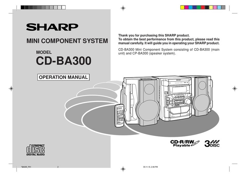
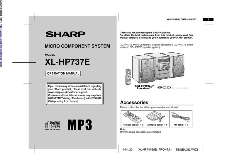
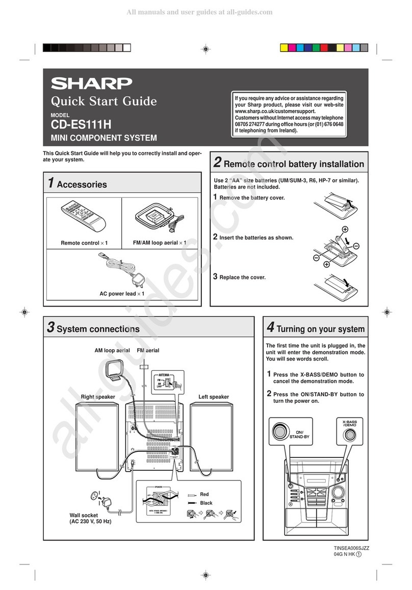
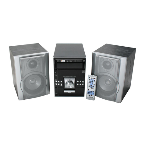
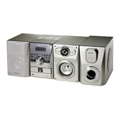
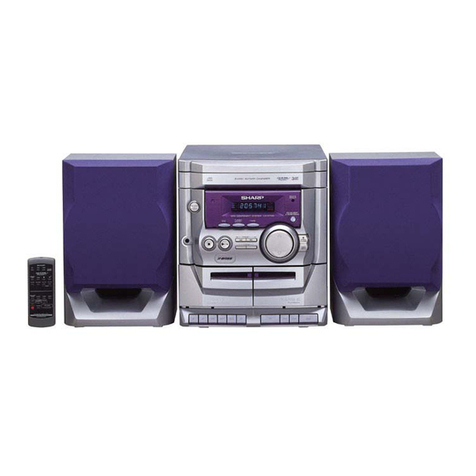
Sharp CD-C1800 User manual

CD-C1800/C,CP-C1800
– 1 –
CD-C1800
CD-C1800C
CP-C1800
CD-C1800 and CP-C1800 constitute CD-C1800.
CD-C1800C and CP-C1800 constitute CD-C1800C.
CONTENTS OF CD-C1800/CD-C1800C,CP-C1800 Page
IMPORTANT SERVICE NOTES (FOR CD-C1800 ONLY) ................................................................................................ 2
SPECIFICATIONS ............................................................................................................................................................. 2
NAMES OF PARTS ........................................................................................................................................................... 3
RESETTING THE MICROCOMPUTER............................................................................................................................. 4
QUICK GUIDE ................................................................................................................................................................... 5
DISASSEMBLY.................................................................................................................................................................. 6
REMOVING AND REINSTALLING THE MAIN PARTS..................................................................................................... 8
PARTS GUIDE/EXPLODED VIEW
PACKING OF THE SET (FOR CD-C1800 ONLY)
• In the interests of user-safety the set should be restored to its
original condition and only parts identical to those specified be
used.
SERVICE MANUAL
SHARP CORPORATION
No. S5835CDC1800C
This document has been published to be used
for after sales service only.
The contents are subject to change without notice.
ThemachineCD-C1800/CD-C1800C,CP-C1800isamodification
of CD-C406/CD-C406C,CP-C406 by providing the Front Panel.
Its performance and operation are identical with those of CD-
C406/CD-C406C,CP-C406. Fordetailsrefexfotheservicemanual
(No. S1810CDC406//) for CD-C406/CD-C406C,CP-C406.
Page
ADJUSTMENT ......................................................................... 9
NOTES ON SCHEMATIC DIAGRAM .................................... 11
TYPE OF TRANSISTER........................................................ 11
WAVEFORMS OF CD CIRCUIT............................................ 12
BLOCK DIAGRAM ................................................................. 13
SCHEMATIC DIAGRAM / WIRING SIDE OF P.W.BOARD... 16
VOLTAGE .............................................................................. 28
TROUBLESHOOTING........................................................... 29
FUNCTION TABLE OF IC...................................................... 33
FL DISPLAY........................................................................... 39
PARTS GUIDE.............................. (INTEGRATED CIRCUITS ~
CD MECHANISM PARTS/P.W.B. ASSEMBLY)
EXPLODED VIEW ........ (CD MECHANISM EXPLODED VIEW)
CD-C406/CD-C406C,CP-C406

CD-C1800/C,CP-C1800
– 2 –
FOR A COMPLETE DESCRIPTION OF THE OPERATION OF THIS UNIT, PLEASE REFER
TO THE OPERATION MANUAL.
CD-C1800/CD-C1800C
CP-C1800
IMPORTANT SERVICE NOTES (FOR CD-C1800 ONLY)
BEFORE RETURNING THE AUDIO PRODUCT
(Fire & Shock Hazard)
Before returning the audio product to the user, perform the
following safety checks.
1. Inspect all lead dress to make certain that leads are not
pinchedorthathardwareisnotlodgedbetweenthechassis
and other metal parts in the audio product.
2. Inspect all protective devices such as insulating materials,
cabinet, terminal board, adjustment and compartment
covers or shields, mechanical insulators etc.
3. To be sure that no shock hazard exists, check for leakage
current in the following manner.
* Plug the AC line cord directly into a 120 volt AC outlet.
* Using two clip leads, connect a 1.5k ohm, 10 watt resistor
paralleled by a 0.15µF capacitor in series with all exposed
metal cabinet parts and a known earth ground, such as
conduit or electrical ground connected to earth ground.
* Use a VTVM or VOM with 1000 ohm per volt, or higher,
sensitivity to measure the AC voltage drop across the
resistor (See diagram).
* Connect the resistor connection to all exposed metal parts
havingareturnpathtothechassis(antenna,metalcabinet,
screw heads, knobs and control shafts, escutcheon, etc.)
and measure the AC voltage drop across the resistor.
AllcheckmustberepeatedwiththeAClinecordplugconnection
reversed.
Anyreadingof0.3voltRMS(thiscorrespondsto0.2milliamp.
AC.) or more is excessive and indicates a potential shock
hazard which must be corrected before returning the audio
product to the owner.
SPECIFICATIONS
Specifications for this model are subject to change without prior
notice.
AC SCALE
VTVM
1.5k ohms
10W
0.15µF
TEST PROBE
TO EXPOSED
METAL PARTS
CONNECT TO
KNOWN EARTH
GROUND
●General
Power source: AC 120 V, 60 Hz
Power consumption: 40 W
Dimensions: Width; 10-5/8" (270 mm)
Height; 11-1/16" (280 mm)
Depth; 13-3/4" (348 mm)
Weight: 9.5 lbs. (4.3 kg)
●Amplifier section
Output power:
(CD-C1800) 10 watts minimum RMS per
channel into 8 ohms from 100
Hz to 20 kHz, 10 % total har-
monic distortion
Output terminals: Speakers; 8 ohms
Headphones; 16-50 ohms
(recommended; 32 ohms)
●Tuner section
Frequency range: FM; 87.5-108 MHz
AM; 530-1,720 kHz
●Cassette deck section
Frequency response: 50-14,000 Hz (Normal tape)
Signal/noise ratio: 50 dB (TAPE 1, recording/
playback)
55 dB (TAPE 2, playback)
Wow and flutter: 0.15 % (WRMS)
●Compact disc player section
Type: 3-disc multi-play compact disc
player
Signal readout: Non-contact, 3-beam semi-con-
ductor laser pickup
D/A converter: 1-bit D/A converter
Frequency response: 20 - 20,000 Hz
Dynamic range: 90 dB (1 kHz)
●Speaker section
Type: 2-way type [4" (10 cm) woofer
and super tweeter]
Maximum input
power: 20 W
Impedance: 8 ohms
Dimensions: Width; 6-11/16" (170 mm)
Height; 11-1/16" (280 mm)
Depth; 5-15/16" (151 mm)
Weight: 3.1 lbs. (1.4 kg)/each
Output power:
(CD-C1800C) MPO; 36 W (18 W + 18 W
(10 % T.H.D.)
RMS; 20 W (10 W + 10 W)
(10 % T.H.D.)

CD-C1800/C,CP-C1800
– 3 –
NAMES OF PARTS
CD-C1800/CD-C1800C
1
ST
X-BASS
MEMORY
123
23 4 6
8
5
7
9
10 11 12 13
14
15
16 17 18 19 20 21 22 23
24 25
2627282930 31 32
■Front panel
11.
Disc Tray
12.
CD Play Indicator:
13.
Disc Number Indicators
14.
FM Stereo Mode Indicator: ST
15.
Extra Bass Indicator: X-BASS
16.
Memory Indicator
17.
CD Pause Indicator:
18.
CD Repeat Indicator:
19.
FM Stereo Indicator:
10.
Power Button
11.
Memory Button
12.
Extra Bass Button: X-BASS
13.
Volume Up/Down Buttons: /
14.
Function Selector Button
15.
Band Selector Button
16.
Tuning Up/Down Buttons: /
17.
(CD) Track Down/Review Button: /
3
(TUNER) Preset Down Button:
18.
Stop Button:
19.
Play/Repeat Button: /
20.
(CD) Track Up/Cue Button: /
3
(TUNER) Preset Up Button:
21.
Disc Skip Button
22.
Open/Close Button:
23.
Headphone Socket
24.
(TAPE 1) Cassette Compartment
25.
(TAPE 2) Cassette Compartment
26.
(TAPE 1) Record Button:
27.
(TAPE 1) Play Button:
28.
(TAPE 1) Rewind Button:
29.
(TAPE 1) Fast Forward Button:
30.
(TAPE 1) Stop/Eject Button: /
31.
(TAPE 2) Play Button:
32.
(TAPE 2) Stop/Eject Button: /

CD-C1800/C,CP-C1800
– 4 –
CP-C1800
CD-C1800/CD-C1800C
CD-C1800/CD-C1800C
■Rear panel
11.
AC Power Input Socket
12.
Speaker Terminals
13.
FM/AM Loop Aerial Socket
●Speaker section
14.
Super Tweeter
15.
Woofer
16.
Bass Reflex Duct
17.
Speaker Wire
■Remote control
11.
Remote Control Transmitter LED
12.
Stop Button:
13.
(CD) Track Down/Review Button: /
3
(TUNER) Preset Down Button:
14.
(CD) Track Up/Cue Button: /
3
(TUNER) Preset Up Button:
15.
Play/Repeat Button:
16.
Disc Skip Button
17.
Pause Button:
18.
Memory Button
19.
Clear Button
10.
Extra Bass Button: X-BASS
11.
Function Selector Buttons
12.
Power Button
13.
Volume Up/Down Buttons: /
RESETTING THE MICROCOMPUTER
Reset the microcomputer by performing the following
procedure for the cases shown below:
●To erase all of the stored memory contents, or
●If the display does not function properly, or
●The unit does not operate properly.
1
Press the POWER button to turn the power off.
2
Press and hold down the POWER button and the ■button
at the same time. Hold them down for at least 1 second.
3
Press the POWER button to turn the power on.
2
1,2,3
Caution:
●The operation explained above will erase all data stored in
memory including tuner and CD presets.
1
2
3
67
4
5
1
2
3
4
5
6
7
89
10
11
12 13

CD-C1800/C,CP-C1800
– 5 –
QUICK GUIDE
MINI COMPONENT SYSTEM
CD-C1800
Quick-Guide
Guía rápida
Preparation for use
Preparación para su uso
15
15
OPEN
/CLOSE
OPEN
/CLOSE
FUNCTION
POWER
POWER
Turning the power on and off
Conexión y desconexión de la
alimentación
Remote control
Control remoto
CD playback
Reproducción de discos compactos
Precaution
●FM Antenna ●AM Loop Antenna
●Right
Speaker ●Left
Speaker
●AC 120 V, 60 Hz
●Connect the wire with the white line to the
minus (−) terminal and the plain wire to the
plus (+) terminal.
●2 "AA" batteries
●Batteries are not included.
Remote Sensor
8" - 20' (0.2m - 6m)
●"Cd" will appear
in the display. ●Label facing up
●The sound level at a given volume setting
depends on a combination of speaker efficiency,
location and many other factors. It is advisable
to avoid exposure to high volume levels, which
occur while turning the unit on with the volume
control setting up high, or while continually
listening at high volume levels.
●Only discs bearing the logo as
shown can be played in this
unit.
●
Antena de FM
●
Antena de cuadro de AM
●
Altavoz
derecho
●
Altavoz
izquierdo
●
120 V de CA, 60 Hz
●
Conecte el cable con la línea blanca al
terminal negativo (-) y el cable sin línea al
terminal positivo (+).
●
Dos pilas "AA"
●
Las pilas no están incluidas.
Sensor remote
0,2m - 6m
●
"Cd" aparecerá
en el visualizador.
●
Etiqueta hacia arriba
FUNCTION
TAPE 1 TAPE 2
STOP/EJECT PLAY STOP/EJECT
FUNCTION
TAPE 1
RECORD
STOP/EJECT
BAND
TUNING TUNING
FUNCTION
ST
FM STEREO
FM MONO
AM
VOLUME
UP • • •
DOWN •
X-BASS
VOLUME
TINSZ0318AWZZ Printed in Malaysia
Impreso en Malaysia
A9803.YT
Recording from CDs
Grabación de discos compactos
Tape playback
Reproducción de cintas
Radio operation
Funcionamiento de la radio
Precaución
Sound control
Control del sonido
●"Cd" will appear
in the display.
●Load the disc to
be recorded.
●CD recording starts.
●"Tape" will appear
in the display.
●"Tuner" will appear
in the display.
●Volume
●Extra-BASS
●
"Cd" aparecerá
en el visualizador.
●
Introduzca el disco
que va a grabar.
●
La grabación de
CD empieza.
●
"Tape" aparecerá
en el visualizador.
●
"Tuner" aparecerá
en el visualizador.
●•
El nivel de sonido en una posición de volumen
fijado depende de una combinación del
rendimiento de las altavoces, la posición y
muchos otros factores. Es aconsejable evitar un
aumento de volumen. Esto se produce, por
ejemplo, al conectar el aparato con el volumen
puesto en una posición alta. Evite continuar la
audición prolongada a altos
niveles de sonido.
●•
En este aparato sólo pueden
reproducirse los discos que
tengan el logotipo mostrado.
●
Volumen
●
Graves extra
VOLUME
UP • • •
DOWN •
X-BASS
X-BASS

CD-C1800/C,CP-C1800
– 6 –
DISASSEMBLY
Caution on Disassembly
Follow the below-mentioned notes when disassembling
the unit and reassembling it, to keep it safe and ensure
excellent performance:
1. Take cassette tape and compact disc out of the unit.
2. Be sure to remove the power supply plug from the wall
outlet before starting to disassemble the unit.
3.Takeoffnylon bands orwireholderswhere they needto
beremovedwhendisassemblingtheunit.Afterservicing
theunit,besure to rearrangetheleadswhere they were
before disassembling.
4. Take sufficient care on static electricity of integrated
circuits and other circuits when servicing.
Figure 6-2
Figure 6-3
1 Top Cabinet 1. Screw ..................... (A1) x4 6-1
2 Side Panel 1. Screw ..................... (B1) x4 6-1
(Left/right) 2. Screw ..................... (B2) x2
3 CD Player Unit/ 1. Turn on the power supply, 6-2
CD Tray Cover open the disc tray, take out
the CD cover, and close.
(Note 1)
2. Hook....................... (C1) x3
3. Hook....................... (C2) x2
4. Socket .................... (C3) x4
4 Back Board 1. Screw ..................... (D1) x3 6-2
5 Main PWB/ 1. Screw ..................... (E1) x10 7-1
Display PWB 2. Hook....................... (E2) x2
3. Socket .................... (E3) x6
6 Front Panel 1. Screw ..................... (F1) x2 7-1
2. Hook....................... (F2) x3
7 Tape Mechanism 1. Open the cassette holder. 7-2
2. Screw...................... (G1) x6
8 Turntable 1. Screw ..................... (H1) x1 7-3
2. Cover ..................... (H2) x1
9 Disc Tray 1. Screw ..................... (J1) x2 7-3
2. Guide ..................... (J2) x2
10 CD Changer 1. Screw ..................... (K1) x4 7-4
Mechanism
11 CD Mechanism 1. Screw ..................... (L1) x1 7-4
STEP REMOVAL PROCEDURE FIGURE
Note 1:
How to open the change manually.
1. Insert the tip of fine screwdriver into the hole of CD player
base, and press down the worm wheel <A>. (Fig. 6-3)
2. Then, turn fully the lock lever in the arrow direction through
the hole on the loading chassis bottom in this state.
After that, push forward the CD player base. (Fig. 6-4)
3. After removing the connector for the optical pickup fromthe
connector wrap the conductive aluminium foil around the
front end of connector so as to protect the optical pickup
from electrostatic damage.
CP-C1800
STEP REMOVAL PROCEDURE FIGURE
1 Speaker 1. Net ..........................(A1) x1 7-5
2. Duct Panel ..............(A2) x1
3. Screw...................... (A3) x4 7-6
Figure 6-1
Top Cabinet
(A1)x2
ø3x12mm
(A1)x2
ø3x12mm
(B2)x1
ø3x12mm
(B2)x1
ø3x12mm
(B1)x4
ø3x12mm
Hook
Hook Side Panel
(Left)
Side Panel
(Right)
Back Board
Front Panel
Back Board
CD Tray Cover
CD Player Unit
Hook
Driver
Push
Hook
(C1)x3
Hook
Driver
Push (C2)x1
(C2)x1
(C3)x4
(D1)x2
ø3x10mm
(D1)x1
ø3x10mm
Front Panel
< A >
LOCK
LEVER
CD-C1800/CD-C1800C
CD-C1800/CD-C1800C
Figure 6-4

CD-C1800/C,CP-C1800
– 7 –
Figure 7-3
Be careful when installing the CD changer mechanism.
InstalltheCDchangermechanismontheCDplayerbaseafter
the shift lever has been set in the highest position.
Figure 7-4
Figure 7-6
CP-C1800
Figure 7-2
Figure 7-1
Figure 7-5
Front Panel Hook
(E2)x2
Display PWB
Main PWB
Hook
(F2)x3
(E1)x8
ø3x10mm
(E1)x2
ø3x10mm
(F1)x2
ø3x10mm
(E3)x1
(E3)x1
(E3)x1
(E3)x3
Front Panel
Tape
Mechanism Open
Cassette
Holder
(Left/Right)
(G1)x6
ø3x10mm
(J1) x1
ø3 x10mm
(J1) x1
ø3 x10mm
(H1) x1
ø3 x10mm
Turntable
Disc Tray
(H2) x1
(J2) x1
(J2) x1
CD Player Unit
Washer
(K1) x4
ø3 x12mm
(L1) x1
ø2.6 x10mm
CD Changer
Mechanism
CD Mechanism
Shift Lever
CD Player Base
Driver Driver should be
pried away from
Speaker Box.
Direction of handle
Net
(A1) x1
Speaker Box
Duct Panel
(A2) x1
Woofer
Speaker Box
Super
Tweeter
(A3) x4
ø4x12mm

CD-C1800/C,CP-C1800
– 8 –
How to remove the turntable up/down motor
(See Fig. 8-1)
1. Remove the screws (A1) x 2 pcs., to remove the turntable
up/down motor.
How to remove the pickup (See Fig. 8-2)
1.Removethescrews(B1) x 2 pcs.,toremovethe shaft (B2).
2. Remove the stop washer (B3) x 1 pc., to remove the gear
(B4).
3. Remove the pickup.
Figure 8-2
REMOVING AND REINSTALLING THE MAIN PARTS
CD MECHANISM SECTION
Perform steps 1, 2, 3, and 8 ~ 11 of the disassembly method
to remove the CD mechanism.
Figure 8-1
(A1) x2
ø2 x5mm
Turntable Up/Down Motor
(B1) x2
(B2) x1 (B3) x1 (B4) x1 CD Mechanism
Pickup
ø2.6 x6mm
Note:
After disconnecting the optical pickup connector wrap the
front end of connector in conductive aluminum foil so as to
prevent damage to the optical pickup by static electricity.

CD-C1800/C,CP-C1800
– 9 –
PARTS GUIDE
NOTE:
Parts marked with “ ” are important for maintaining the safety of the set.
Besuretoreplacepartswithspecifiedonesfor maintainingthesafetyandperformanceofthe set.
“HOW TO ORDER REPLACEMENT PARTS”
To have your order filled promptly and correctly, please furnish the
following information.
1. MODEL NUMBER 2. REF. No.
3. PART NO. 4. DESCRIPTION
MARK: SPARE PARTS-DELIVERY SECTION
Explanation of capacitors/resistors parts codes
For U.S.A. only
Contact your nearest SHARP Parts Distributor to order.
For location of SHARP Parts Distributor,
Please call Toll-Free;
1-800-BE-SHARP
Capacitors
VCC ....................... Ceramic type
VCK........................ Ceramic type
VCT........................ Semiconductor type
VC • • MF ............... Cylindrical type (without lead wire)
VC • • MN............... Cylindrical type (without lead wire)
VC • • TV................ Square type (without lead wire)
VC • • TQ ............... Square type (without lead wire)
VC • • CY ............... Square type (without lead wire)
VC • • CZ ............... Square type (without lead wire)
VC • • • • • • • • • J .. The 13th character represents capacity difference.
("J" ±5%, "K" ±10%, "M" ±20%, "N" ±30%,
"C" ±0.25 pF, "D" ±0.5 pF, "Z" +80-20%.)
If there are no indications for the electrolytic capacitors, error is ±20%.
Resistors
VRD ....................... Carbon-film type
VRS........................ Carbon-film type
VRN ....................... Metal-film type
VR • • MF ............... Cylindrical type (without lead wire)
VR • • MN............... Cylindrical type (without lead wire)
VR • • TV................ Square type (without lead wire)
VR • • TQ ............... Square type (without lead wire)
VR • • CY ............... Square type (without lead wire)
VR • • CZ ............... Square type (without lead wire)
VR • • • • • • • • • J .. The 13th character represents error.
("J" ±5%, "F" ±1%, "D" ±0.5%.)
If there are no indications for other parts, the resistors are ±5%
carbon-film type.
MODEL CD-C1800
CD-C1800C
CP-C1800

PRICE
RANK
DESCRIPTIONNO. PART CODE NO. PARTS CODE
PRICE
RANK
DESCRIPTION
CD-C1800/C,CP-C1800
CABINET PARTS
201 92LCAB2790AS1 J AW Front Panel Ass’y
201- 1 ———— — Front Panel
(Not Replacement Item)
201- 2 HDECQ0351AWSA J AG Panel,LCD Display
201- 3 GCOVA1204AWSA J AD Cover,Remote Sensor
202 GITAR0342AWSA J AG Back Board [CD-C1800]
202 GITAR0343AWSA J AG Back Board [CD-C1800C]
203 GITAS0035AWSA J AG Side Panel,Left
204 GITAS0036AWSA J AG Side Panel,Right
205 GCAB-1046AWSA J AL Top Cabinet
206 GCOVA1203AWSA J AH Cover,CD Tray
207 92LLABL1784F J AC Label,UL Caution
[CD-C1800 Only]
208 92LCSPR1596A J AA Spring,Cassette Holder Up
209 JBTN-0117AWSA J AD Button,Record [Tape 1]
210 JBTN-0118AWSA J AD Button,Play [Tape 1]
211 JBTN-0119AWSA J AD Button,Rew [Tape 1]
212 JBTN-0120AWSA J AD Button,FF [Tape 1]
213 JBTN-0121AWSA J AD Button,Stop [Tape 1]
214 JBTN-0122AWSA J AD Button,Play [Tape 2]
215 LCHSM0054AWSA J AH Main Chassis
217 JBTN-0123AWSA J AD Button,Stop [Tape 2]
218 PRDAR0080AWFW J AG Heat Sink
219 LHLDZ3007AWFW J AB Holder,LCD
220 MSPRD0044AWFJ J AB Spring,Lock Lever
221 MLEVP0067AWZZ J AC Lever,Lock
222 NROLP0009AWZZ J AB Roller
223 LCHSZ0010AWZZ J AM Loading Chassis
224 MLEVP0070AWZZ J AB Lever,Turntable Lock
225 MSPRC0020AWFJ J AB Spring,Turntable Lock Lever
226 GCAB-1044AWSA J AM CD Player Base
228 LHLDZ1139AWSA J AD Support,Stabilizer
229 92LHOLD2037AS1 J AK Stabilizer Ass’y
229- 1 ———— — Stabilizer
(Not Replacement Item)
229- 2 PMAGF0001AWZZ J AF Magnet
229- 3 92LSUPT1749D J AA Support,Magnet
230 NTNT-0018AWSA J AK Turntable
231 LHLDZ1140AWZZ J AB Guide
232 MLEVP0068AWZZ J AB Lever,Change
233 MSPRC0024AWFW J AB Spring,Solenoid
234 LCHSZ0011AWZZ J AG Chassis,CD Mechanism
235 NGERK0004AWZZ J AB Gear,Bevel
237 NGERW0006AWZZ J AC Gear,Worm Wheel
238 NPLYD0001AWZZ J AB Pulley
239 NGERK0005AWZZ J AB Gear,Loading
240 MLEVP0066AWZZ J AE Lever,Shift
241 NGERH0064AWZZ J AD Gear,Cam
242 NGERK0003AWZZ J AC Gear,Drive
243 LHLDZ1141AWZZ J AB Support,Pitch
244 NGERH0065AWZZ J AB Gear,Turntable
245 NBLTK0029AWZZ J AB Belt,Drive
246 92LN-BAND1318A J AA Nylon Band,80mm
247 RPLU-0002AWZZ J AH Solenoid Ass’y
248 92LCOV2790CTS1 J AM Cassette Cover Ass’y,Tape 1
248- 1 ———— — Cassette Cover,Tape 1
(Not Replacement Item)
248- 2 HDECQ0352AWSA J AD Panel,Cassette Cover,Tape 1
249 92LCOV2790CTS2 J AM Cassette Cover Ass’y,Tape 2
249- 1 ———— — Cassette Cover,Tape 2
(Not Replacement Item)
249- 2 HDECQ0353AWSA J AD Panel,Cassette Cover,Tape 2
250 MLIFP0001AWSA J AG Damper
251 JKNBZ0528AWSA J AF Button,Stop
252 JKNBZ0527AWSA J AG Button,Function
253 JKNBZ0524AWSA J AF Button,Volume Up/Down
254 JKNBZ0525AWSA J AE Button,X-BASS
255 JKNBZ0526AWSA J AF Button,Power
256 92LRDAT-1468B J AE Heat Sink
257 92LMECHA2790A J BG Tape Mechanism Ass’y
257- 1 92LM-BELT1651B J AB FR Belt
257- 2 92LMBELT1658A1 J AC Drive Belt [Tape 1]
257- 3 92LMBELT1658B1 J AC Drive Belt [Tape 2]
257- 4 92LM-EH1658A J AG Head,Erase
257- 5 92LM-PRA1651A J AE Pinch Roller Ass’y
257- 6 92LM-RPH1746A J AM Head,Record/Playback
257- 7(M601) RMOTM0004AWM1 J AR Motor with Pulley [Tape]
257- 8(SW605) 92LM-SW1491A J AE Switch,Leaf Type [Tape 1 Main]
257- 9(SW606) 92LM-SW1491A J AE Switch,Leaf Type [Tape 2 Main]
257-10(SW607) 92LM-SW1658A J AB Switch,Leaf Type [Tape 1 Rec.]
257-11(SW608) 92LM-SW1658A J AB Switch,Leaf Type [Tape 2 Play]
258 TLABS0091AWZZ J AB Label,NOM [CD-C1800 Only]
259 TLABS0058AWZZ J AB Label,SJ [CD-C1800 Only]
260 TLABS0155AWZZ J AC Label,Caution [CD-C1800 Only]
261 QLUGP0001AWZZ J AC Lug
262 GDORF0060AWSA J AF Cassette Holder,Tape 1
263 GDORF0061AWSA J AF Cassette Holder,Tape 2
264 XWHJZ62-09510 J AB Washer,ø6.2×ø10×0.9mm
265 LANGF0032AWZZ J AC Support,T/T Lock Lever
266 PCUSG0022AWZZ J AB Cushion
601 XEBSD30P10000 J AA Screw,ø3×10mm
602 XESSD30P10000 J AA Screw,ø3×10mm
603 XEBSD30P12000 J AA Screw,ø3×12mm
605 XEBSF30P12000 J AA Screw,ø3×12mm
606 LX-JZ0004AWFD J AA Screw,ø3×12mm
607 LX-JZ0002AWFD J AA Screw,ø3×10mm
608 LX-EZ0005AWFD J AA Screw,Special
609 XJSSF30P10000 J AA Screw,ø3×10mm
610 XBPSD26P05JSO J AB Screw,ø2.6×5mm
611 LX-TZ0019AFZZ J AB Screw,Special
612 XEBSD26P12000 J AA Screw,ø2.6×12mm
613 XJBSF30P10000 J AA Screw,ø3×10mm
614 XJBSD30P10000 J AA Screw,ø3×10mm
615 XJBSD30P08000 J AA Screw,ø3×8mm
PACKING PARTS (CD-C1800C)
SPAKA0196AWZZ J AN Packing Add.,Left/Right
SPAKC0657AWZZ J AQ Packing Case
SPAKP0013AWZZ1 J AC Polyethylene Bag,Unit
TLABRF216AWZZ J AB Label,Bar Code
92LBAG1460C1 J AB Polyethylene Bag,Accessories
ACCESSORIES
!QACCD0010AW00 J AR AC Power Supply Cord
[CD-C1800]
!QACCD0015AW00 J AM AC Power Supply Cord
[CD-C1800C]
QANTL0004AWZZ J AG FM/AM Loop Antenna
TINSE0215AWZZ1 J Operation Manual [CD-C1800]
TINSK0071AWZZ J AF Operation Manual [CD-C1800C]
TINSZ0318AWZZ J AE Quick Guide
RRMCG0103AWSA J AR Remote Control
92LLID1782A J AQ Battery Lid,Remote Control
SPEAKER BOX PARTS
701 92L121-0144 J AU Net Frame Ass’y
702 92L051-0014 J AX Speaker Box Ass’y
703 92L291-0034 J AF Cord,Speaker
704 92L372-0006 J AD Screw,ø4×12mm
705 92L351-0302 J AC Label,Specifications
706 92L316-0026 J AG Panel,Duct
707 92L394-0026 J AB Port Cushion
SP1,2 VSP0010PBT18A J AQ Speaker,Woofer
SP3,4 92L124-0016 J AK Super Tweeter Ass’y
PACKING PARTS (CD-C1800C)
92L411-0019 J AB Polyethylene Bag,Speaker
92L412-0121 J Packing Add.,Top/Bottom
ACCESSORY
92L353-0073 J AF Feature Label,Speaker
CD-C1800/CD-C1800C
CP-C1800
– 1 –
CD-C1800/C,CP-C1800
Figure 2 CABINET EXPLODED VIEW (1/2)
A
B
C
D
E
F
G
H
123456
– 2 –
Note: Only the unit and consumale parts are supplied as aprts supply for the Tape mechanism.
CD-C1800/CD-C1800C

CD-C1800/C,CP-C1800
A
B
C
D
E
F
G
H
123456
Figure 3 CABINET EXPLODED VIEW (2/2)
– 3 –
CD-C1800/CD-C1800C
CD
MECHANISM
601
222
220
607
221
223 222
601
231
603x4
222
233
247
PWB-C
610x2
SW2 232
239
240
241
242
243
612
611
244 245
611
238
237
222x2
222
222
207
222
SW3
226
609 228
230
605x2
605x2
205
206
235
235
234
608
225
224
229-1
229-2
229-3
264
229
M3
615
265
266
(CD-C1800
Only)
231

CD-C1800/C,CP-C1800
Figure 4 SPEAKER EXPLODED VIEW
A
B
C
D
E
F
G
H
123456
– 4 –
CP-C1800
703
WOOFER
SUPER TWEETER
SP3 (L-CH)
SP4 (R-CH)
SP3(L-CH)
SP4(R-CH)
SP1(L-CH)
SP2(R-CH)
WOOFER
701
SP1(L-CH)
SP2(R-CH)
704x4
SP1(L-CH)
SP2(R-CH)
706
707x2
702
705
RED BLACK
BLACK
SUPER
TWEETER
SP3 (L-CH)
SP4 (R-CH)

CD-C1800/C,CP-C1800
PACKING OFF THE SET (FOR CD-C1800 ONLY)
Setting position of switches and knobs
Tape Mechanism STOP
Not Replacement Item
– 5 –
FRONT
TOP
BOTTOM
SPAKP0013AWZZ1
Polyethylene Bag,Unit
SPAKA0196AWZZ
Packing Add., Left/Right
SPAKC0656AWZZ
Packing Case
92LBAG1460C1
Polyethylene Bag,
Accessories
TLABR0974AWZZ
Bar code Label
TLABS0092AWZZ
NOM, Label [Mexico Only]
92L411-0019
Polyethylene Bag,
Speaker
92L353-0073
Label, Feature
Speaker
92L412-0121
Packing Add.,
Speaker
(Top/Bottom)
AC Power Supply Cord
Remote Control
Operation Manual
Quick Guide
FM/AM Loop Antenna
Left
Right
TOP
FRONT

CD-C1800/C,CP-C1800
– 6 –
- MEMO -

CD-C1800/C,CP-C1800
COPYRIGHT 1998 BY SHARP COPORATION
ALL RIGHTS RESERVED.
No part of this publication may be reproduced,
stored in a retrieval system, or transmitted in
any from or by any means, electronic, mechanical,
photocopying, recording, or otherwise, without
prior written permission of the publisher.
A9805-2428NS•HA•M
SC • LAG • SL
SHARP CORPORATION
Communication Systems Group
Quality & Reliability Control Center
Higashihiroshima, Hiroshima 739-0192, Japan
Printed in Japan
©
This manual suits for next models
2
Table of contents
Other Sharp Stereo System manuals

Sharp
Sharp CD-E500H User manual

Sharp
Sharp XL-55H User manual

Sharp
Sharp QT-CD700W User manual

Sharp
Sharp XL-DH20NH User manual

Sharp
Sharp GF-800H User manual

Sharp
Sharp QT-95H User manual

Sharp
Sharp CD-DD4500 User manual

Sharp
Sharp CD-MPS600 User manual

Sharp
Sharp XL-HP500H User manual

Sharp
Sharp XL-B720D User manual

Sharp
Sharp CD-C410H User manual

Sharp
Sharp CD-BK133W User manual

Sharp
Sharp XL-E100H User manual

Sharp
Sharp CD-MPX860H User manual

Sharp
Sharp CD-G10000 User manual

Sharp
Sharp SD-NX10 User manual

Sharp
Sharp GF-7850H User manual

Sharp
Sharp XL-3000C User manual

Sharp
Sharp XL-MP35H User manual

Sharp
Sharp XL-DAB9H User manual