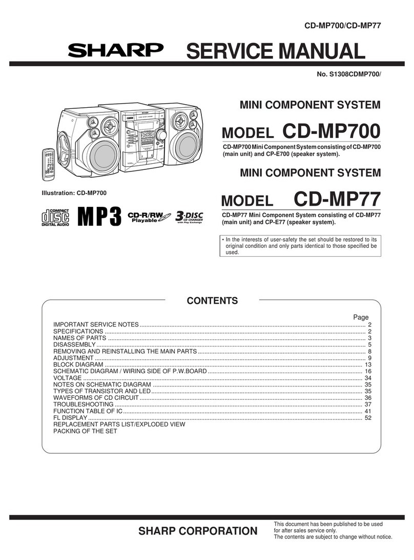
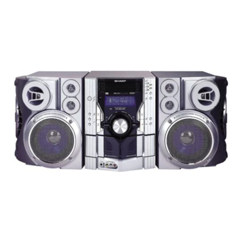
Sharp CD-C500Z User manual

SHARP
SERVICE
MANUAL
DIGITAL
AUDIO
001
DOLBY
SYSTEM
l
Dolby noise reduction manufactured under license from Dolby
Laboratories Licensing Corporation.
“DOLBY” and the double-D symbol
00
are trademarks of
Dolby Laboratories Licensing Corporation.
l
In the interests of user-safety the set should be restored to its original
condition and only parts identical to those specified be used.
1%
i
/
INDEX
TO
CONTENTS
Page
SPECIFICATIONS .........................................................
.2
NAMESOFPARTS ......................................................3-6
VOLTAGE SEl.&CTION
OPERATION MANUAL
....................................................
.6
DISASSEMBLY.. ............................................................................ . . . . . . . . . . .
::‘,:-:
2”
REMOVING AND REINSTALLING THE MAIN PARTS
........................
13115
CHANGER MECHANISM OPERATION
.....................................
16,17
ADJUSTMENT
.......................................................
18-21
TROUBLESHOOTING(CD SECTION)
.....................................22-26
FUNCTION TABLE OF IC
/
BLOCK DIAGRAM OF IC
..........................27-33
BLOCKDIAGRAM .....................................................34-36
SCHEMATIC DIAGRAM/WIRING
SIDE
OF P.W.BOARD .....................37-57
NOTES ON SCHEMATIC DIAGRAM
..........................................58
TYPES OF TRANSISTOR AND LED
..........................................59
AC POWER SUPPLY CORD AND AC PLUG ADAPTOR
.........................
.59
EXPLODED VIEW.. ....................................................60-6 6
REPLACEMENT PARTS LIST
...........................................67-80
SHARP
CORPORATION

FOR A COMPLETE DESCRIPTION OF THE OPERATION OF THIS UNIT, PLEASE
REFER TO THE OPERATION MANUAL.
SPECIFICATIONS
B
Compact
disc
stereo
music
system
0
General
Power source: AC
110
V/l
27 Vi220 VI
230-240
V,
50160
Hz
Power consumption:
160 W
Dimensions:
Width; 270 mm
(lo-5/8”)
Height; 316 mm (12-7/16”)
Weight:
Depth; 300 mm
(11-13116”)
7.8
kg (17.2 Ibs.}
0
Amplifier
section
Peak music power
output:
Music power output:
Continuous power
output:
input sensitivity and
input impedance:
Load impedance:
l
Tuner
section
Frequency range:
320
W
2 x 40
W,
10 % T.H.D.
2 x 21
W, 10 % T.H.D.
AUWVIDEO;
500 mV/47 kohms
Mixing microphone; 1 mV/
1 kohms
Speakers; 6 ohms
(Main speaker; 16 ohms)
(Super woofer; 8 ohms)
Headphones; 16
-
50 ohms
(recommended; 32 ohms)
FM; 88.0
-
108 MHz
SWZ;
9.5
-
21.85 MHz
SWl;
3.2
-
7.3 MHz
MW; 531
-
1,602
kHz
(9
kHz
span)
MW; 530
-
1,620
kHz
(10
kHz
span),
0
Compact
disc
player section
Type:
6-disc
magazine type compact
disc player
Non-contact, 3-beam semi-
conductor laser pickup
200
-
500 rpm CLV, Approx.
CIRC
(Cross Interleave Reed-
Solomon Code)
4-times oversampling digital filter
and active filter
20
-
20,000
Hz
95
dB
(1
kHz)
90
cl6
(1
kHz)
Unmeasurable
(less than 0.001% W. peak)
Signal readout:
Rota&al
speed:
Error correction:
Filter:
Frequency response:
Signal/noise ratio:
Dynamic range:
Wow and flutter:
0
Cassette
deck
section
Tape: .
“‘*”
..),A
‘-
:?>
Compact cassette tape
Frequency
reyy.=
50
-
14,000 Hz (Normal tape)
‘,
.L<&
50
-
15,000 Hz
(00~
tape)
S/N ratio:
:-
.,y:,
”
:4-
.i*.
Dolby NR
off;
50
dB
_j
.I
“’
.,,
‘“:<-
Dolby
NR
effect; 10
dB
.:
;,a**
Wow and flutter:
(at over 5
kHz)
“;OXG’%,(WRMS)
n
Speaker
system
Speakers:
Rated power:
Maximum power
handling capacity:
Impedance:
Dimensions:
Weight:
.
2-way
12 cm
(4-3/4”)
woofer and
5
c-m*
(2”) tweeter
fype
.-
. .
. .
10 w
20 w
16
ohms
Width; 158 mm
(6-l/4”)
Height; 316 mm
(12-7116”)
Depth; 256 mm (lo”)
2.9 kg (6.4 Ibs.) /each
n
Super
woofer
System
Speakers:
Rated power:
lOcm(4”)x2
21 w
Maximum power
handling capacity: 40 w
Impedance:
8
ohms
Dimensions:
Width; 158 mm
(6-l/4”)
Height; 316 mm (12-7/16”)
Weight:
Depth:
256?-nm
(10”)
3.7
kg (8.2 tbs.)
Specifications for this model are subject to change without prior
notice.
-2-

NAMES
OF
PARTS
///
3
45
+
6
7
8
14
15
16 17
19
20
21
22
23
24
25 26
27
$1
32
33
n
Tuner control
section
1.
Band indicators
2. Station Frequency
3. Preset Channel Indicator
4. FM Stereo Indicator:
cc
5.
FM Stereo Mode Indicator
6.
Auto Scan indicator
7. Memory Indicator
8.
Preset Channel
Up/Down
Buttons
9.
Band Selector Button
10.
FM Mode Button
11.
Auto Scan/Manual Tuning Selector Button
12.
Tuning Up/Down Buttons
13.
Memory Button
n
CD
control section
14.
Pause Indicator: II
15.
Play indicator:
)
16.
Disc Number Indicators
17.
Track Number Indicator
18.
Minutes and Seconds
IndicatoriProgramme Number Indicator
19.
Repeat Indicator: c
20.
Music Schedule Over Indicator
21.
Music Schedule Indicators
22. Programme Indicator
23.
Random Play Indicator
24.
Disc Number Select Buttons
25.
Magazine Compartment
26.
Pause Button: II
27.
Play Button:
)
28.
Track Up/Down Buttons:
W
I
W
29.
Eject Button:
r
30.
Stop Button:
n
31, Mixing Microphone Socket
32.
Mixing Microphone Level Control
33.
CD Magazine
-3-

1
2
345
6
7
8
9
IO
Ii
12
13
14 15 16
jTAPE2
j
1
n
I
I
II
R
17
18
19
20
21
22 23
24
25
26
TAPE
2
/
TAPE
1
I
n
Amplifier section
1.
Power Switch
2. Graphic Equalizer Controls (LEFT)
3.
Remote Control Sensor
4. Extra Bass Indicator: X-BASS
5.
TAPE 1) Direction Indicators
6.
Graphic Equalizer Controls (RIGHT)
7. Dolby NR Switch
8.
Tape Selector Switch
9.
Dubbing Speed Switch
10.
Power On/Stand-By Indicator
Il.
Function Selector Buttons and Indicators
12.
Balance Control
13.
Volume Control
n
Tape control section
14.
TAPE 2) Cassette
Co&artment
15. Headphones Socket
16.
TAPE 1) Cassette Compartment
17.
Record Button:
0
18.
Play Button:
b
19.
Rewind Button:
U
20.
Fast Forward Button:
H
21.
StoplEject Button:
n
/r
22.
Pause Button: II
23.
Reverse Mode Switch:
c;i
I
3
24.
Play Button:
4,
25.
Fast Wind Buttons:
M
1
H
26.
Stop/Eject Button:
n
,&
27.
Direction Switch:
41,
-4-

4
5
6
8 9
-5-
-6-
n
Rear
pane1
‘.
MWlSWllSW2
Asrlal
Terminal
2.
MW/SWl/SWP
Aerial
Earth
Terminal
3.
FM
Aerial
Terminals
4.
Auxiliary
I
Video
(Audio
Signal)
Input
Sockets
5.
Span
Selector
Switch
6.
Beat Cancel Switch
7.
AC
vduge
Sslsctor
6.
AC Supply Lead
9.
Speaker
Terminals
I14
-
15
-
16
-
17
-
18
-
19
-
20
60”
n
Names of controls
1.
Remote
Control
Transmitter
Window
2.
Extra
Sass
Button
:
X-SASS
3.
Power Button
4.
Function Selector Buttons
5.
Volume
Up/Down
Buttons
S
Tuner
control buttons
6.
Band Selector Buttons
7.
Preset
Channel
Up/Down
Buttons
l
CD
control buttons
6.
stop Sutton:
.
9.
Disc
Skip
Button
10.
Cue
Sutton:
H
11.
Review
Sutton:
44
12.
Disc Number Select Buttons
13.
Track Number Select Buttons
14.
Pauss
Button:
I,
15.
Play
Button:
t
16.
Track Up/Down Buttons:
I+
,
m
17.
Repeat
Sutton:
c
16.
Random Play
Sutton
19.
Memory
Button
20.
Clear
Button
q
Proper use of the remote control
Aim the remote control at the remote control sensor
with,”
60” with no obstacles, and operate as shown.
Notes
concsrnlng
uss:
0
Replace the batteries if control distance decreases
or
operation becomes erratic.
l
Periodically clean the transmitter wlndow on the
rsrnote
control and the sensor on the main unit with a soft
cloth.
0
Exposing the sensor on the main unit to strong light can
interfere with ooeration.Chanoe the lighting or the
dlrec.
tion of the
unit:
0
Keep the remote control away from moisture, excessive
heat. shock, and wbratlons.
0
The
remote
control’8
usable range
IS
between 0.2
m
(6”)
and 6
m
(20’) away from the sensor.
VOLTAGE
SELECTION
The voltage selector
IS
located on the rear of the unit. If ad-
]ustment is necessary, use a screwdriver
I”
order to turn the
selector
m
either
direction until the correct voltage figure
IS
displayed
m
the
window
next to the adjustment screw.

m
3
1
2
n
APSS
(Auto
Program
Search
System)
5
1
23
-
n
APMS
(Automatic
Programmable
Music
Selector)

P!AY
REPEPlT
1

DISASSEMBLY
Caution
on
Disassembly
Follow the below-mentioned notes when disassembling the
unit and reassembling it, to keep its safety and excellent
performance:
1.
Take cassette tape and CD magazine out of the
unit.
2. Be sure to remove the power supply plug from the wall
outlet before starting to disassemble the unit.
3. Take off nylon bands or wire holders where they need be
removed when disassembling the unit. After servicing the
unit,
be sure to rearrange the leads where they were before
disassembling.
4.
Takesufficientcareonstaticelectricityoftntegratedcircuits
and other circuits when servicing.
Figure
12-1
msp,ay
PWS
Figure
12-2
4
/
Back Board
1.screw ...........(Dl)X 5
11-Z
5
CD Block
1.screw
........
..(El)
x
411-3
2. Socket
........
.(EP)x
3
Figure
1
l-l
Figure
12-3
Figure
12-4
Figure
11-2
‘l!Y
Figure
12-5
,A21X2
a3xl2mm
Figure
12-6
Figure
11-3
Figure
12-7
*
Figure
12-8
-
11
-
-
12-

REMOVING
AND
REINSTALLING
THE MAIN PARTS
TAPE MECHANISM SECTION
Perform steps
1,
2, 3. 4, 5, 6, and 7 of the disassembly method
to remove the tape mechanism.
How to remove the main,
FF/rewind
belt (See
Fig. 13-1.)
1. Remove the
Mann
belt, (Al) x
1
PC.,
at the tape 2 side from
the motor pulley.
2.
Remove the main belt, (A2) x1 pc.,at the tape 1 side from the
motor pulley.
3. Remove the FF/Rewlnd belt, (A3) x
1
PC.,
from the tlywheel
of tape 2.
4.
Put on the belts in the reverse order of removal.
Note:
1.
When putiing on the belt, ascertain that the belt is not busted,
and clean
It.
How to remove the T2 motor (See Fig. 13-2.)
1.
Remove the screw,
(El)
x1
PC.,
and remove the motor fixture.
2. Remove the screws,
(82)
x2
PCS.,
and remove the motor.
How to remove the
Tl
motor (See Fig. 13-2.)
1.
Remove the screws, (83) x2 pcs.,and remove the motor
fc&re
2.
Remove the screws,
(84)
x3 pcs.,and remove the motor.
Note:
1.
When mounting the motor, pay attention to the motor bracket.
2. When the motor is removedShe belt comes off Put it on,
referrlng to the description of belt putting-on.
How to remove the flywheel of tape 1 side (See
Fig. 13-3.)
1.
Remove the drive belt.
2. Remove the washers,
(Cl),(C3)
and the stop wasper, (C2)
with a small precision screwdriver to extract the flywheel from
the chassis.
How to remove the flywheel of tape 2 side. (See
Fig. 1’3-2 and 13-3.)
1.
Remove the drive belt.
2.
Remove the screws, (83) x2
PCS.,
and remove the motor
fixture.
3.
Remove the stop washer, (C4) with a small precision screw-
driver to extract the flywheel from the chassis.
Note:
1.
When the stop washer
IS
deformed or damaged, replace it
with a new one.
Figure 13-l
Figure 13-2
How to remove the pinch roller of tape 1 side
(See
Fig.l4-1.)
1. Remove the stop washer,
(Dl)
with a small precision
screwdriver, and remove the pinch roller.
How to remove the pinch roller of tape 2 side
(See Fig. 14-l.)
1. Carefully release the pinch roller hook in the
directIon
indicated by the arrow mark, and remove the pinch roller.
How to remove the playback head (See Fig.
14-2.)
1. Remove the screws, (El) x2
PCS.,
and remove the button
block.
2.
Remove the screws, (EZ),(E3), and remove the head.
How to remove the record/playback and
erase heads (See Fig. 14-2)
1. Remove the
screws,(E4).(E5),and
remove the
record/playback head.
2.
Removethescrews,
(E6)xZpcqandremovetheerase
head.
Be sure to apply screw lock after replacement of head and
azimuth adjustment.
Figure 14-1
Figure 14-2
Figure 13-3
-
13
-
14-
CD MECHANISM SECTION
Perform steps
1,2,
3,4,5
and 10 of the disassembly method to
remove the CD mechanism.
Replacement of pickup (See Figs. 15-1 and
15-2.)
When replacingthe pickup, refer to “Cares when Handling Plckup
Assembly”.
(a) After removing the CD
mechamsm
according to the
disassembling procedure, remove the screws, shafts and
connectors in order of
0,
0,
0,
and
@,
and replace the
pickup.
(b) Fit a new pickup in reverse order of disassembling. After
fittmg,
lock it with the screw
0.
(c)
Connect the connector and lead wire as it was.
(d)
The laser power adjustment is not necessary owing to
improvement of performance of pickup.
Note:
When replacing the pickup do not apply force to the turntable of
spin motor. Otherwise, the height of main chass% and turntable
may be varied.
After replacing the pickup
This new mechanism has been newly designed to enhance
remarkably its performance as compared to the former ones, so
that there is no need to adjust pickup posture.
’
After mounting the pickup. apply voltage to the slide motor, and
ascertain that it runs at DC 1.5V or less.
CD CHANGER MECHANISM SECTION
Removing the CD changer motor (See Figs.
15-3 and
15-4.)
1. Before remowng the motor mounting chassis, turn the load
gear and lift gear in the direction of the arrow as far as it will
go.
2. Remove the 3 chassis screws (Al) which hold the loading
motor and lift motor.
3. Removethe other 2 screws (A2) which hold the loading motor,
and remove it.
4. Remove the last 2 screws (A3) which hold the lift motor, and
remove it.
How to remove a CD magazine when it cannot
be ejected (See Fig. 15-3.)
1. If the CD magazine is locked and cannot be ejected due to
trouble, Remove the cabinet, and turn the load gear
counterclockwise manually to eject the CD magazine. (See
Fig 15-3.)
Figure
15-1
Rock
Gear
Figure 15-2
Figure
15-3
CA21
$js2.6x3mm
imld
Molar
I
CHANGER
MECHANISM
OPERATION
This changer mechamsm consists of 6 changers. Magazines are
m%xted by hand, and microcomputer operabon is not
performed.
DISC
tray unloading, disc chuckmg, disc tray storage, magazine
discharge and disc tray selection are performed by the
microcomputer.
1.
For microcomputer operation, see the IC function table.
2. For the timing charts, see Figs.
16,17-i
and 17-2 shown
below.
Figure154
-
15-
Figure
16
-
16-

Time
Chart(StoP
To
PlaY
4th
DISC
To
StoPI
stop
p;;::e
Magazine
’
Lift
Motor
Down
Loadlnh
’
(1st
DISO)
(sqttonra~,esc)
(4th
To
1st
DISC)
1st
DISC)
yfl~lne
LOCK
___________.________-----.--------.----.---
___
__
__--__--__---__-----____________________-----------
-__-_-----_
Play
hlOadln6
Loading
StoP
UnloadIns
4th
DISC
LoadIns
Figure
17-l
Time
Chart(Llft
Motor
UP
/
Down)
DISC
I
(SWSM)
Photo-Jnterruptsr
LoadIns
h0TOR
(Close)
+
~7;la
,tv0TOR3
40mS
UnloadIns
ComPlsta
Lift
Motor
Down
Complete
LoadlnG
Complete UnloadInS
ComPiete
Lift
Motor
UP
ComPlete Loading
ComPiste
Figure 17-2
-
17-

ADJUSTMENT
As for preparation for adjustment, adjusting method and re-
placement of pickup refer to the relevant explanation in Service
Manual “ADJUSTMENT PROCEDURES OF AUDIO
PRO-
MECHANISM
SECTION
l
Driving Force Check
Torque Meter Specified Value
Tape 1
Play: TW-2412
Over
50 g
Tape 2
’
Over 60 g
Reverse Play: TW-2422 Over 50 g Over 60 g
l
Torque Check
Torque Meter
Specified Value
Tape 1 Tape 2
Play: TW-2111
27 to 60
gem
27 to 60 g.cm
Reverse Play: TW-2121
27 to 60
gem
27 to 60 g.cm
Fast Forward: TW-2231
55 to 120
gem
55 to 120 g.cm
Rewind: TW-2231
55 to 120 g.cm 55 to 120
gem
l
Head Azimuth
Test Tape Instrument Connection
MTT-114
Headphones socket
(Load resistance: 32 ohms)
l
Tape Speed
Test Tape Adjusting Specified Instrument
i
Point Value Connection
High
Ml-T-1 11 Tape1 :
6,000
i
Speaker
speed*
VR404 100 Hz
terminal (Load
Tape2: resistance: 6
j
VR402 ohms)
Normal
MTT-111
Tape1 :
3,000
+
speed
VR401
i
60 Hz
i
Tape2:
1
VR403
*Short TP402 @and TP402
0
when performing the high speed
adjustment.
TAPE
SECTION
!
L
Position of each switch or control
Volume Max
Graphic Equalizer Center
Function
Tape
Dolby NR Off
Beat cancel
A
Tape selector Normal
Dubbing speed Normal
l
Bias Frequency
Adjusting
Specified Value Instrument
Point
!
Connection
L411
100
kHz
Q421 Emitter
/
(BEAT CANCEL Switch : A)
l
Bias Current
1
Adjusting Point Specified Value Instrument
’
Connection
L: VR407
Normal: 20
i
3 V L: Pin 1 of
CNP404*
R: VR408
PI:
Pin 5 of
GNP404
l
Erase Current Check
Resistor for measurement:
1ohm
Specified Value
30i7mV
l
Playback Amplifier Sensitivity
r
Tast Tape Adjusting Specified
Point Value Instrument Connection
1
t
MT-T-1 50
L: VR405
1
R:
VP,406
Normal:
L: Pin3 of TP401
560
mV
R:
Pin1
of TP401
l
Record /Playback Sensitivity (Tape 2)
Test Tape: UR-121
Input Level Adjusting Specified Instrument Connection
Point Value
l
1
L: VR409
Ret
Level: Input: AuxAIideo
R: VR410 103
mV Output:TP401
* 1: Adjust the oscillator so that TP401 output is 103 mV in the
recording mode.
l
Playback Amplifier Sensitivity Check
Test Tape
1
Specified
Instrument
Value
Connection
2.7 V
+
3dB Speaker terminal
(Load resistance:6 ohms)
Figure 18 ADJUSTMENT POINTS
-
18-

c
TUNER
SECTION
fL:
Low-range frequency
fH:
High-range frequency
l
AM
IF/RF
Signal generator: 400 Hz,
30%,
AM modulated
Span Selector Switch:
9kHz
Test Stage Frequency Frequency Specified
Instrumc
Display Value/
Connecti
Adjusting
Point
IF
450
kHz
1,602
kHz T209
l
1
MW
band
-
531
kHz T207(fL):
l
2
coverage 1.1
vrt
0.05 v
MW
603
kHz
603
kHz T203(fL)
‘1
tracking 1,404
kHz
1,404
kHz
TC203(fH)
SW1
band
3.2 MHz 3.2 MHz
T206(fL):
*3
coverage 2.1
v+
0.05 v
7.3 MHz 7.3 MHz
TC206(fH):
7.7 Vk
0.05 v
SW1
tracking
3.9 MHz 3.9 MHz
T202(fL)
‘I
7.1 MHz 7.1 MHz
TC202(fH)
SW2 band
coverage
I::,:.,,*;
ent
on
0.05
v
SW2
11.65 MHz 11.65 MHz
T201
(fL)
*l
tracking
21.45 MHz 21.45 MHz TC20l(fM)
*1.
input: Antenna
*2.
Input: Antenna
Output: Pin 15 of
IC202 Output: Collector of Q216
*3.
input: Antenna
Output: Collector of 0214
~.
i
l
FM
IF/RF
Signal generator: 1
kHz,
40
kHz
dev., FM modulated
Test
Stage Frequency Frequency Setting/ Instrument
Display
Adjusting Connection
Point
Band
-
67.5 MHz
1324
(fL):
l
l
coverage
1
.a5
v
i
50
mV
RF
98.00 MHz 98.00 MHz
T321
ST322
l
2
(1 O-30
dB)
IF
98.00 MHz 98.00 MHz
-
*2
(1 O-30
dB)
*l
.Input:Antenna
0utput:Collector of
Q216
*2Jnput:Antenna
0utput:Pin 12 of
IC202
l
FM
Detection/Distortion
Signal generator: 1
kHz,
40
kHz
dev, FM modulated
l
FM
Auto
Stop
Level
Signal generator: 1
kHz,
40
kHz
dev, FM modulated
Frequency Frequency Adjusting Instrument Connection
Display
Point
98.00 MHz 98.00 MHz
VFi202*
)
(30
dB)
Input: Antenna
Obtput:
Speaker
terminal
* Adjust so that an output signal appears.
l
VCO
Frequency
*Adjust for 38
kHz
i
100 Hz.
u
-.
T210
I
-
VR202
R271
A?-,“;
Figure 19 ADJUSTMENT POINTS
-
19-

CD
SECTION
1.
Preparation
for
Adjustment
When adjusting, be sure to refer to Service Manual
“ADJUSTMENT PROCEDURES OF AUDIO PRODUCTS”.
l
Test
mode
of
control
microcomputer
Depressing the FF button and REW button, turn on the power
switch.
2.
VCO
Free-Run
Frequency
Adjusting Specified
Value
Point
VR6
4.320
MHz
I
15
kHz
Instrument Connection
Pin 9 of ICl and GND.
3.
Servo
Unit
The procedure of adjustment differs from that stated in Service
Manual“ADJUSTMENT PROCEDURES OF AUDIO
PRODUCTS”.
Follow the procedure stated below.
l
Focus
Offset
Adjusting Specified Value Instrument Connection
Point
VR3
Oi50mV
Pin 2 and pin 1 (GND) of
CNP2.
l
Tracking
Off
set
Adjusting Specified Value
Point
VR2
Oi50mV
Instrument Connection
Pin 4 and pin 1 (GND) of
CNP2.
l
Tracking
Error
Balance
Adjusting Adjusting Method Instrument Connection
Point
VR4
l
1
TPl
(TGl) and GND.
*1
: Short-circuit the Pin 4 of
IC4
and GND.
Adjust so as to obtain symmetric waveform (Figure 20-2)
when DC is 0 V.
l
Focus
Gain
* 2:
Apply sine wave (Oscillation Frequency: 1
.O
kHz 1 .O Vrms)
as shown in Figure
20-3.
l
Tracking
Gain
Adjusting Adjusting Method Instrument Connection
Point
VR5
Adjust so that the
TPl
(TGl)(TG2)
voltage of CH-1 is equal
and GND.
i
*
/
to that of CH-2.
l
3
3: Apply sine wave (Oscillation Frequency:
1
.O
kHz
1 .O Vrms)
as shown in Figure 21-I.
Check again the focus offset, tracking offset and tracking
error balance.
l
Check
HF
output
1
Adjusting
(
Adjusting Method
1
Instrument Connection
Point
/
__
__
1
TPl
(HF) and GND.
/
Make sure that waveform is as shown in Figure 21-2.
GNDo
!
1
I
I
-
I,
I
1
I
-------------I
;RACKING
ERROR
BALANCE
ADJ.
JIG
DC=OL
I
-I
Figure
20-l
TRACKING ERROR BALANCE
More than
1.
ZVP-P
Figure 20-2 TRACKING ERROR BALANCE
IOOK
3. 3K
I
~~-~--~~~~-----~~~-J
FOUCUS
GAIN ADJ. JIG
Figure 20-3 FOCUS GAIN
-
20
-

R79
220
r----q70-----------~
I
I
1
I
*..
100K
GENERATOR
I
I
470
i
--------------------~
TRACKING
GAIN
ADJ.
JIG
i
I
I
I
I
I
0%’
”
’
+
’
11
1
Figure 21-1 TRACKING GAIN Figure 21-2 HF OUTPUT
ICI
1
-.I
3
7
TGI
TG2
HF
FG2
FGI
GND
@PI
VRI
EEl
@+@JjL
GE
VR2
t
1.
65-2.
I
VP-P
25
IEF
I
i
I
Figure 21-3 ADJUSTMENT POINTS
-21
-

TROUBLESHOOTING
(CD
SECTION)
l
Remove the cabinet and follow the troubleshooting
instructions.
Turn the power switch on the unit to ON.
j
*
Check the item of “The disc is not up/down.”
Does the spin motor run?
-/
Check the item of “The spin motor does not run.”
Yes
No
*
When the disc is initialized, is TOC read?
Is TOC set to the playback mode?
1
Yes
No
9
Check the item of “The disc does not playback.”
Is there any audio
outpu
No
Check the audio circuit.
I
Turn the power switch to ON.
I
1
Check the power circuit voltage.
I
I
i
1
’
i
Is the oscillating circuit (XL801) of the control
microcomputer
(IC801)
operating normally?
Yes
-- Check the XL801 and peripheral circuits and replace
No
faulty parts.
Check to see that the reset circuit of the control
microcomputer
(IC801)
is operating normally.
Normal
1
Defectivec
Check the reset circuit
(lC802)
and peripheral circuits and
’
I
replace faulty parts.
I
Is the drive signal of the LCD or fluorescent character
/
The microcomputer
(IC801)
is defective. Replace it.
.
Yes
Check the supply voltage of the
LCV1
Oefect,ve*&
I
, character display tube. The LCD or fluorescent character display tube is defective.
/
II
1
Normal
+
Are the connector and PWB pattern damaaed?
j
Normal
I
-
22
-

Is the standby switch signal(L) being input to pin 50 of the
control microcomputer(lC801)?
T/
Replace the standby switch.
Is the loading end switch signal (H) being input to pin 49
of the control microcomputer
(IC801)?
/
,
Noi
Replace the loading end switch.
I
!
Yes
/
Is the motor drive output being output from pins 43 and 45
/of
7
The control microcomputer
(IC801)
is defective. Replace it.
Yes
Is the motor drive output being output from pins 3 and 10 Is there
+10.5V
at pins 7 and 9 of
IC6?
of the motor driver
(IC6)?
No
~
,
/
Yes
The loading motor (M3) is defective. Replace it.
The loading mechanism is faulty.
:
i
No
>
Check to see if the PWB pattefn to
the power supply is damaged.
control microcomputer
(IC801)?
The disc 1 switch is defective. Replace it.
Is the photo-interrupter signal (H) being input to pin 47 of
p
Replace the photo-interrupter.
the control microcomputer
(IC801)?
No
Yes
Is the motor drive output being output from pins 43 and 45
of the control microcomputer
(IC801)?
No*
The control microcomputer
(IC801)
is defective. Replace it,
Yes
Is the motor drive output being output from pins 2 and 10
p
Is there
+10.5V
at pins 7 and 9 of
IC6?
of the motor driver
(IC6)?
’
b
No
I
i
Yes
The lift motor (M4) is defective. Replace it.
The lift mechanism is faulty.
r
Check to see
If
the PWB pattern to
Check the output of pins 53 (DM+) and 54 (DM-)
of
ICl.
(
Normal
i
Check the output of pin 2 of
IC5.
Normal
Defective
____*
IC5
is defective. Replace it.
Spin motor M2 is defective. Replace it.
-
23
-

Is the disc initialized?
1
b/
Does the laser diode go on?
7
Yes
/
A Check the item of “The laser diode goes on.”
!
4
B Check the item of “The laser diode does not
go
on.”
1
Does the tracking servo operate normally?
Is the EFM signal of pin 36 of
IC2
flat? (Lower side)
Yes
Normal
/
Is there any dropout part in the EFM siqnal of pin 36 of
,
IC2?
-
Yes
Replace the disc or change the program.
Is the tracking error signal (pin 2 of IC2) being output?
____*
No
No+m
Is the tracking signal being output
I
I
I
from the
oickuo
main unit?
I
I,
I/
Yes Yes
*
rF$lace
the
1
In the stop mode, is the tracking coil drive output (pin 4 of
‘7
Incorrect adjustment
1
CNPP)
0 SOmV? In the stop mode, adjust the tracking offset to 0
‘I
50mV.
/
j
Yes
Is the tracking coil drive output being output from the
tracking driver output (pin 2 of
IC4)?
I
Yes
-
IC4
is defective.
i
NO
The PWB negative pattern is damaged.
The pickup connecting connector is broken.
The pickup tracking coil is broken.
. ,
-24-

When the magazine is closed
without loading disc, does the
pickup lens tray move up and
down?
Is the EFM signal of pin 36 of
IC2
1
being output?
No
+)
l
Pickup height error
--
-
/
l
Laser diode output error
I
/
No
i
Are the voltages at pins 10 and 5
of the focus driver (IC4)
+7.3V
and
-7.3V,
respectively?
I
Is the FRF disc reflection signal
of pin 69 of the servo signal
control
(ICl)
at a high level?
I
-i
!
-
Yes
Is the high/low level repetition
output for leading the focus servo
.
y
ICl
is defective.
/
No
Yes
!
Yes
No
i
Yes
Is the output of pin 31 of
IC2
as
shown below?
_
._
Pin
69
of
ICI
FRF
Pin
31
of
IC2
FE
Yes
*
Is the high/low repetition output
’
Check to see
thit
the focus circuit is normal and check
being output from pin 8 of
IC4?
the distribution connector.
1
The pickup is defective. Replace it.
The servo amplifier (IC2) is
defective.
-
The servo amplifier (IC2) is
No
defective.
-
The focus driver (IC4) is defective. Replace it.
NO
)
Yes
i
Check connectors CNS2A/B and,
CNP2.
-
,
-25-

Is the laser control signal of pin 38 (LANF) of the
microcomputer
(IC801)
at a low level?
+
Is the Q7 laser diode driver
’
No
emitter voltage
+5V?
Yes
Replace the optical pickup.
Is the pickup returned to the innermost part?
Is the pickup in switch SW1 turned to ON?
Yes
Check if pins 57 (FEM+) and 58 (FEM-) of ICI are
outputting.
Defective
l
ICl
is defective. Replace it.
1
Normal
Check pin 8 of the slide motor driver (IC5).
Normal
The slide motor driver(lC5) is defective.Repace it.
Check if there is voltage at
CNP3,CNSS
and Ml.
Is there audio output?
!
No
Is there audio output from both L
and-R
channels?
Yes
e
l
Check the muting Transistor, Q6 and Q8 and replace.
No
l
Check the sound coupling capacitors Cl5(L-CH)
andClG(R-CH).
1
Is there
+
5V at
IC9?
Yes
hi
Check power circuits
ICI2
and
IC13.
No
r
Is pin 36 of
ICSOI
muting output at a high level?
e
Replace
IC801.
No
Yes
.
1
Is pin 3 of Q6 and Q8 at a low level?
\-
No
Check the voltage of QlO and
Ql
I
and replace faulty
parts.
Yes
-26-
This manual suits for next models
5
Table of contents
Other Sharp Stereo System manuals

Sharp
Sharp XLDV50 User manual

Sharp
Sharp GBOXS0072AWM1 User manual

Sharp
Sharp CMS-R70CDH User manual

Sharp
Sharp CD-BA250H User manual

Sharp
Sharp CD-E250E User manual

Sharp
Sharp XL-S15H User manual

Sharp
Sharp XL-3000W User manual

Sharp
Sharp CD-XP120H User manual

Sharp
Sharp CD-MPX870 User manual

Sharp
Sharp CD-BA1200H User manual

Sharp
Sharp CD-E100H User manual

Sharp
Sharp CD-BA250H User manual

Sharp
Sharp CD-SW440N User manual

Sharp
Sharp CD-BA300 User manual

Sharp
Sharp XL-LS703B User manual

Sharp
Sharp QT-CD250H User manual

Sharp
Sharp SD-CX1H User manual

Sharp
Sharp XL-1500H User manual

Sharp
Sharp QT-CD180W User manual

Sharp
Sharp GX-CD1300MP MK2 User manual