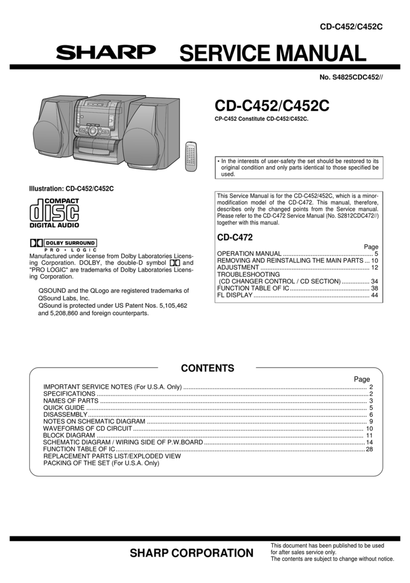
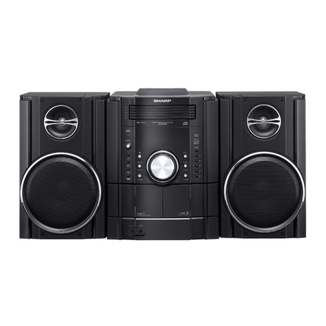
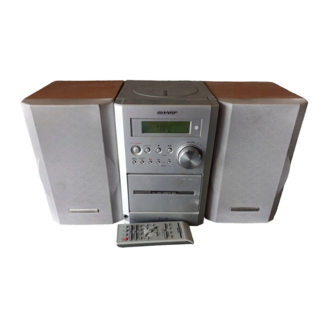
Sharp SD-CX1W(BL) User manual

SD-CX1W
CONTENTS Page
SAFETY PRECAUTION OF MD SECTION FOR SERVICE MANUAL..............................................................................2
SAFETY PRECAUTION OF CD SECTION FOR SERVICE MANUAL ..............................................................................3
VOLTAGE SELECTION..................................................................................................................................................... 3
AC POWER SUPPLY CORD AND AC PLUG ADAPTOR ................................................................................................. 3
SPECIFICATIONS ............................................................................................................................................................. 4
NAMES OF PARTS ........................................................................................................................................................... 5
OPERATION MANUAL ...................................................................................................................................................... 7
DISASSEMBLY................................................................................................................................................................ 10
REMOVING AND REINSTALLING THE MAIN PARTS................................................................................................... 13
DESCRIPTION OF CIRCUIT FOR 1-BIT AMP. UNIT ..................................................................................................... 15
TO CHECK AND CANCEL PROTECT CIRCUIT DETECTION LINE.............................................................................. 16
TEST MODE .................................................................................................................................................................... 17
ADJUSTMENT ................................................................................................................................................................. 22
ERROR MESSAGE LIST................................................................................................................................................. 31
EEPROM WRITING PROCEDURE ................................................................................................................................. 32
NOTES ON SCHEMATIC DIAGRAM .............................................................................................................................. 35
TYPES OF TRANSISTOR AND LED............................................................................................................................... 35
BLOCK DIAGRAM ........................................................................................................................................................... 36
SCHEMATIC DIAGRAM .................................................................................................................................................. 40
WIRING SIDE OF P.W.BOARD....................................................................................................................................... 54
WAVEFORMS OF 1 BIT AMP. CIRCUIT......................................................................................................................... 67
WAVEFORMS OF MD CIRCUIT ..................................................................................................................................... 68
WAVEFORMS OF CD CIRCUIT...................................................................................................................................... 70
TROUBLESHOOTING ..................................................................................................................................................... 72
FUNCTION TABLE OF IC................................................................................................................................................ 81
FL DISPLAY......................................................................................................................................................................98
PARTS GUIDE/EXPLODED VIEW
SERVICE MANUAL
SHARP CORPORATION
No. S3117SDCX1WBL
• In the interests of user-safety the set should be restored to its original
condition and only parts identical to those specified should be used.
This document has been published to be used
for after sales service only.
The contents are subject to change without notice.
SD-CX1W(BL)
SD-CX1W(GR)
SD-CX1W 1-Bit Digital Audio System consisting of SD-CX1W (main
unit) and CP-CX1W (speaker system).
MODEL
1-BIT DIGITAL AUDIO SYSTEM

SD-CX1W
– 2 –
SAFETY PRECAUTION OF MD SECTION FOR SERVICE MANUAL
The AEL (Accessible Emisson Level) of the laser power output is less than class 1 but the laser component is capable of emitting radiation
exceeding the limit for Class 1. Therefore it is important that the following precautions are observer during servicing to protect your eyes
against exposure to the laser beam.
1) When the unit case cover is removed and LOADING switch (SW1932) is turned on and then PLAY switch (SW1934 mechanism PWB)
is turned on in a few second.
The laser will light for several second to detect a disk.
2) The laser power output of the pickup unit and replacement service parts are all factory pre-set before shipment.
Do not attempt to re-adjust the laser pickup unit during replacement or servicing.
3) Under no circumstances stare into the pickup lens at any time.
4) If laser optical unit becomes faulty, replace the complete laser optical unit.
5) CAUTION-Use of controls or adjustments, or performance of procedures other than those specified herein may result in hazardous
radiation exposure.
Precaution to be taken when replacing and servicing the laser pickup.
The following precautions must be observed during servicing to protect your eyes against exposure to the laser.
Warning of possible eye damage when repairing:
IftheACpowerplugisconnectedwhentheinnercoveroftheunitisremoved,thelaserwilllightupduringfocus access(about
1 second) (Fig. 2-1).
During this operation, the laser will leak from the opening between the magnetic head and cartridge holder (Fig. 2-2).
In order to protect your eyes, you must not look at the laser during repair.
Before repairing, be sure to disconnect the AC power plug.
Figure 2-1 Figure 2-2
Magnetic Head Optical Pickup
WARNINGS
Laser Diode Properties
Material: GaAIAs
Wavelength: 785 nm
Pulse time:
Read mode:0.8 mW Continuous
Write mode:max 10 mW 0.5S
min cycle 1.5S
Repetition
CAUTION - INVISIBLE LASER RADIATION WHEN OPEN AND INTERLOCKS DEFEATED
AVOID EXPOSURE TO BEAM.
VARNING - OSYNLIG LASERSTRÅLNING NÄR DENNA DEL ÄR ÖPPNAD OCH SPÄRRAR
ÄR URKOPPLADE. STRÅLEN ÄR FARLIG.
ADVARSEL- USYNLIG LASERSTRÅLING NÅR DEKSEL ÅPNES OG SIKKERHEDSLÅS
BRYTES. UNNGÅ EKSPONERING FOR STRÅLEN.
VARO! AVATTAESSA JA SUOJALUKITUS OHITETTAESSA OLET ALTTIINA
NÄKYMÄTÖN LASERSÄTEILYLLE. ÄLÄ KATSO SÄTEESEN.
VARNING - OSYNLIG LASERSTRÅLING NÄR DENNA DEL ÄR ÖPPNAD OCH SPÄRREN
ÄR URKOPPLAD. BETRAKTA EJ STRÅLEN.
ADVARSEL- USYNLIG LASERSTRÅLING VED ÅBNING NÅR SIKKERHEDSAFBRYDERE
ER UDE AF FUNKTION. UNDGÅ UDSETTELSE FOR STRÅLING.
,,
Magnetic Head
Optical Pickup
Spindle Motor
Laser Beam
Cartridge Holder
Mechanism
Chassis

– 3 –
SD-CX1W
Precaution to be taken when replacing and servicing the Laser Pickup.
TheAEL(AccessibleEmissionLevel)ofLaserPowerOutputforthismodelisspecifiedtobelowerthanClass1Requirements.
However, the following precautions must be observed during servicing to protect your eyes against exposure to the Laser
beam.
(1) When the cabinet has been removed, the power is turned on without a compact disc, and the Pickup is on a position outer
than the lead-in position, the Laser will light for several seconds to detect a disc. Do not look into the Pickup Lens.
(2) The Laser Power Output of the Pickup inside the unit and replacement service parts have already been adjusted prior to
shipping.
(3) No adjustment to the Laser Power should be attempted when replacing or servicing the Pickup.
(4) Under no circumstances look directly into the Pickup Lens at any time.
(5) CAUTION - Use of controls or adjustments, or performance of procedures other than those specified herein may result in
hazardous radiation exposure.
WARNINGS
SAFETY PRECAUTION OF CD SECTION FOR SERVICE MANUAL
VOLTAGE SELECTION
Before operating the unit on mains, check the preset voltage. If the voltage is different from your local voltage, adjust the voltage
as follows. Turn the selector with a screwdriver until the appropriate voltage number appears in the window (110 V, 127 V,
220 V or 230 V - 240 V AC).
QACCB0008AW00
QACCE0007AW00
QACCL0002AW00
QACCA0004AW00/QACCJ0006AW00
QPLGA0004AWZZ
AC POWER SUPPLY CORD AND AC PLUG ADAPTOR

SD-CX1W
– 4 –
FOR A COMPLETE DESCRIPTION OF THE OPERATION OF THIS UNIT, PLEASE REFER
TO THE OPERATION MANUAL.
SPECIFICATIONS
SD-CX1W
Specifications for this model are subject to change without prior notice.
CP-CX1W
General
Amplifier
CD player
Power source AC 110/127/220/230-240 V, 50/60 Hz
Power consumption 42 W
Dimensions Width: 330 mm (13")
Height: 208 mm (8-3/16")
Depht : 187 mm (7-3/8")
Weight 5.3 kg (11.7 lbs.)
Amplification system 64fs 1-bit switching
(Remarks: fs = 44.1 kHz)
Rated output power RMS: 40 W (20 W + 20 W ) (10% T.H.D.)
A/D noise shaping 7th-order (delta - sigma) modulation
Output terminals Speakers: 6 ohms
Headphones: 16 - 50 ohms (recommended: 32 ohms)
Input terminals Auxiliary: 500 mV/47 kohms
Type 1-disc vertical compact disc player
Signal readout Non-contact, 3-beam semiconductor laser pickup
D/A converter 1-bit D/A converter
Frequency response 20 - 20,000 Hz
Dynamic range 90 db (1 kHz)
MiniDisc
Type MiniDisc Recorder
Signal readout Non-contact, 3-beam semiconductor laser pickup
Rotation speed 400 - 900 rpm CLV, Approx.
Eror correction ACIRC (Advanced Cross Interleave Reed-Solomon Code)
Quantization 20-bit linear (A/D converter)
Coding ATRAC (Adaptive TRansform Acoustic Coding), ATRAC3
Sampling frequenvy 44.1 kHz
Recording method Magnetic modulation overwrite method
Frequency response 20 - 20,000 Hz
D/A converter 1-bit D/A converter
Wow and flutter Unmeasurable (less than 0.001% W. peak)
Signal/noise ratio 95 dB (1 kHz)
Dynamic range 90 dB (1 kHz)
Audio channel Stereo: 2 channels (SP, LP2, LP4)
Monaural: 1 channel (MONO)
Frequency range FM: 88 - 108 MHz
AM: 531 - 1,602 kHz
Type 2-way type speaker system
2 cm (13/16") Tweeter
12 cm (4-3/4") Woofer
Maximum input power 40 W
Rated input power 20 W
Impedance 6 ohms
Dimensions Width: 170 mm (6-3/4")
Height: 300 mm (11-13/16")
Depth: 186 mm (7-3/8")
Weght 2.0 kg (4.4 lbs.)/each
Tuner

– 5 –
SD-CX1W
NAMES OF PARTS
SD-CX1W
Front panel
1.CD Cover
2.CD Cover Open/Close Button
3.Remote Sensor
4.Function Indicator
5.Timer Indicator
6.On/Stand-by Button
7.MD Compartment
8.MD Eject Button
9.MD Record Mode Button
10.CD/MD Play Mode Select Button
11.MD Stop Button
12.MD Play/Pause Button
13.CD Stop Button
14.CD Play/Pause Button
15.Volume Up or Down Buttons
16.Headphone Socket
17.Erase Button
18.MD Record Button
19.Auxiliary/Demo Button
20.Tuner (Band) Button
21.CD/MD Fast Reverse, Tuning Down Button
22.MD +10 Track Up Button
23.CD/MD Fast Forward, Tuning Up Button
1234
5
678910
12 13 14 15
16 17 18 19 20 21
11
22 23
Multi-function LCD display
1.Level Meter/Character Information/Frequency Indicator
2.Band Selector Indicator
3.Record Indicator
4.CD/MD Play Indicator
5.Top Position Indicator
6.Record Mode Indicator
7.MD Record Pause Indicator
8.CD/MD Repeat Indicator
9.Surround Indicator
10.Random Play Indicator
11.Programme Play Indicator
12.Sound Synchronised Recording Indicator
13.Track Edit Indicator
14.TOC Indicator
15.FM Stereo Indicator
16.FM Stereo Mode Indicator
17.Sleep Indicator
18.Timer Play/Recording Indicator
2
1
3
4
6
5
78
10
12 13 14
15
16
17
18
9
11
Rear panel
1.Cooling Fan
2.Speaker Terminals
3.Span Selector Switch
4.FM 75 Ohms Aerial Terminal
5.FM Aerial Earth Terminal
6.AM Aerial Earth Terminal
7.AM Loop Aerial Terminal
8.Voltage Selector
9.AC Input Socket
10.Auxiliary Input Sockets
12
910
3
4
7
5
6
8

SD-CX1W
– 6 –
CP-CX1W
Remote control
1.Remote Control Transmitter
2.CD/MD Play Mode Select Button
3.MD Record Mode Button
4.On/Stand-by Button
5.MD Record Button
6.Top Position Button
7.Track Edit Button
8.Sound Synchronise Record Button
9.Volume Up or Down Button
10.CD/MD Fast Reverse, Tuning Down Button
11.Extra Bass Button
12.CD/MD Programme Button
13.Clear Button
14.Name/TOC-Edit Button
15.Timer/Delete Button
16.Time Button
17.Enter Button
18.MD Stop Button
19.MD Play/Pause Button
20.CD Stop Button
21.CD Play/Pause Button
22.Tuner (Band) Button
23.Auxiliary Button
24.Surround Button
25.CD/MD Fast Forward, Tuning Up Button
26.Preset Equalizer Button
27.Character Input/CD, MD, Tuner Direct Buttons
28.Display Button
29.Recording Level/Cursor/Tuner Preset Buttons
30.CD/MD Edit Buttons
1
2
3
4
5
6
7
8
9
10
11
12
*
*
*
*
*
*
*
*
*
*
18
19
20
21
22
23
24
25
26
27
28
29
30
*
*
*
*
*
*
13
14
15
16
17
Buttons with "
*
" mark in the illustration can be operated on the remote control only.
Other buttons can be operated both on the main unit and the remote control.
1.Speaker Grille
2.Tweeter
3.Woofer
4.Bass Reflex Duct
5.Speaker Terminals
2
3
45
1
Test of the remote control
Check the remote control after checking all connections have been made correctly.
Face the remote control directly to the remote sensor on the unit.
The remote control can be used within the range shown below:
Press the ON/STAND-BY button. Does the power turn on? Now, you can enjoy the
music.
Remote sensor
0.2 m - 6 m
(8" - 20')

– 7 –
SD-CX1W
OPERATION MANUAL
Setting the Clock
In this example, the clock is set for 9:30 15. 02 '01 .
To confirm the time display:
[When the unit is in the stand-by mode]
Press the DISPLAY button on the remote control.
The time display will appear for about 5 seconds.
[When the power is on]
Press the TIMER/DELETE button.
Within 10 seconds, press the REC LEVEL/CURSOR or button.
The time display will appear for about 10 seconds.
Note:
The clock setting will be cleared when the unit is unplugged or the power failure
occurs.
To reset the clock:
Perform "Setting the Clock" from the beginning.
1
Press the ON/STAND-BY button to turn the power on.
2
Press the TIMER/DELETE button.
3
Within 10 seconds, press the REC LEVEL/CURSOR or button to
select the "TIME ADJUST".
4
Within 10 seconds, press the ENTER button.
5
Press the REC LEVEL/CURSOR or button to adjust the year,
and then press the ENTER button.
6
Press the REC LEVEL/CURSOR or button to adjust the month,
and then press the ENTER button.
7
Press the REC LEVEL/CURSOR or button to adjust the date,
and then press the ENTER button.
8
Press the REC LEVEL/CURSOR or button to adjust the hour,
and then press the ENTER button.
9
Press the REC LEVEL/CURSOR or button to adjust the minutes,
and then press the ENTER button.
The hour will not advance even if minutes advance from "59" to "00".
The clock starts from "0" second. (Seconds are not displayed.) The time display
will disappear after a few seconds.
Setting the AC voltage selector
Check the setting of the AC voltage selector located on the rear panel before plug-
ging the unit into an AC socket. If necessary, adjust the selector to correspond to the
AC power voltage used in your area.
Turn the selector with a screwdriver until the appropriate voltage number
appears in the window (110 V, 127 V, 220 V or 230 V - 240 V AC).
Connecting the AC power lead
After making all connections, plug the unit. If you plug the unit first, the unit
will enter the demonstration mode.
Notes:
Plug the AC power lead into an AC socket, after any connections.
Unplug the AC power lead from the AC socket if the unit will not be in use for a pro-
longed period of time.
AC Plug Adaptor
In areas (or countries) where an AC socket as shown in illustration is used, con-
nect the unit using the AC plug adaptor supplied with the unit, as illustrated. The AC
plug adaptor is not included in areas where the AC wall socket and AC power plug
can be directly connected (see illustration ).
Note for users in Australia and New Zealand:
An AC plug adaptor is not supplied if the lead has an Australian Standard plug.
If trouble occurs (reset)
When this product is subjected to strong external interference (mechanical shock,
excessive static electricity, abnormal supply voltage due to lightning, etc.) or if it is
operated incorrectly, it may malfunction.
If such a problem occurs, do the following:
Unplug the power lead from the AC socket. Then, plug it in again and retry the
operation.
Caution:
This operation will erase all data stored in memory including clock, timer settings,
tuner preset, and CD or MiniDisc programme.

SD-CX1W
– 8 –
Setting the FM/AM span selector
The International Telecommunication Union (ITU) has established thatmember coun-
tries should maintain either a 100 kHz or a 50 kHz interval between broadcasting fre-
quencies of FM stations and 10 kHz or 9 kHz for AM station. The illustration shows
the 50/9 kHz zones (regions 1 and 3), and the 100/10 kHz zone (region 2).
Before using the unit, set the SPAN SELECTOR switch (on the rear panel) to the
interval (span) of your area.
To change the tuning zone:
1
Unplug the AC power lead from the AC socket.
2
Set the SPAN SELECTOR switch (on the rear panel) as follows.
For 50 kHz FM interval (9 kHz in AM) 50/9
For 100 kHz FM interval (10 kHz in AM) 100/10
3
Plug the AC power lead to the AC socket.
Caution:
This operation will erase all data stored in memory including clock, timer settings,
tuner preset, and CD or MiniDisc programme.
What is a MiniDisc ?
The disc is stored in a cartridge. You can handle it easily without worrying about dust, fin-
gerprints, etc. However, dust entering the opening of the cartridge, dirt on the cartridge,
warping, etc. may cause malfunctions. Please note the following.
To prevent recorded MiniDiscs from being
erased accidentally
Slide the accidental erase prevention tab, located on the side of the MiniDisc, in the direc-
tion indicated by the arrow.
The MiniDisc is then be protected against accidental erasure.
To add a recording to such a MiniDisc, slide the accidental erase prevention tab back to its
original position.
Helpful tip when attaching a label
When attaching a label to a MiniDisc cartridge, be sure to note the following. If the label is
not attached properly, the MiniDisc may jam inside the unit and it may not be possible to
remove it.
Types of discs
MiniDisc System Limitations
If the label peels off or partially lifts away, replace it with a new
one.
Do not put a new label on top of an existing one.
Attach the label only in the specified location.
There are two types of discs: playback-only and recordable types.
Playback-only MiniDisc:
This type of MiniDisc is used for commercially available
prerecordedmusic.Thisisthe samekindofopticaldisc as
CDs. Playback is performed using an optical pickup. (Re-
cording and editing are not possible.) A Shutter will be used on only
one side (back).
Recordable MiniDisc:
This is a "raw disc" on which recording can be performed.
A magneto optical disc is used. Recordings are made us-
ing a laser and magnetic field. Repeated recording is pos-
sible.
Shutters will be used on both
sides.
Recordable Recording
prevented
Even if the maximum recording
time of a MiniDisc has not been
reached, "TOC FULL" may be
displayed.
In the MD system,the delimiter of the recording area on
a MiniDisc is programmed in a TOC. If partial erasing,
recording and editing are repeated several times, TOC
information will fill up,even though the numberof tracks
has not reached the limit (255 tracks), and further re-
cording will beimpossible. (If you use theall erase func-
tion, this MiniDisc can be used from the beginning.)
Even if the maximum recording
time of a MiniDisc has not been
reached, "DISC FULL" may be
displayed.
If there is any flaw on the MiniDisc, that part is automat-
ically excluded from the space available for recording.
Therefore, the recording time becomes shorter.
Even if several short tracks are
erased,theremainingrecording
time may not show an increase.
When the remaining recording time of a disc is dis-
played, short tracks less than 12 seconds long may not
be included in the total.
Two tracks may not be com-
bined in editing. For MiniDiscs on which repeated recording and editing
operationswereperformed,theCOMBINEfunctionmay
not work. Atrack recorded from a CD (digital recording)
and a track recorded from a radio or other equipment
(analogue recording) cannot be combined.
The total of the recorded time
and time remaining on a disc
maynotadd uptothe maximum
possible recording time.
A cluster (about 2 seconds) is normally the minimum
unit of recording. So, even if a track is less than 2 sec-
onds long, it will use about 2 seconds of space on the
disc. Therefore, the time actually available for recording
may be less than the remaining time displayed.
If there arescratches on discs, those sections will be au-
tomatically avoided (no recording will be placed in those
sections). Therefore, the recording time will be reduced.
If recorded tracks are fast re-
versed or fast forwarded, the
sound may skip.
A MiniDisc which has beenrecorded or edited repeated-
ly may skip during fast reverse or fast forward.

– 9 –
SD-CX1W
Error Messages
When an error message is displayed, proceed as follows:
Error messages Meaning Remedy
BLANK MD Nothing is recorded. (Neither
music nor disc name is re-
corded.)
Replace it with another disc.
Can't COPY You tried to record from a
copy prohibited CD. Replace the CD.
Can't EDIT A track cannot be edited. Change the stop position of the
track and then try editing it.
Can't READ* The disc is damaged. Replace it with another disc.
(*: Number or
symbol) TOC information cannot be
read. Erase the disc and try recording
again.
MiniDisc not specified.
Can't REC Recording cannot be per-
formed correctly due to vibra-
tion or shock in the unit.
Re-record or replace the Mini-
Disc.
Can't T REC Timer recording is impossible
or there is no available space
on the MD.
Replace it with another record-
able disc.
The disc is out of recording
space.
Can't WRITE The TOC information could
not be created properly due to
a mechanical shock or to
scratches on the disc.
Set this unit to the stand-by
mode and try to write the TOC
again. (Remove any source of
shock or vibration whilst writing.)
CD NO DISC A CD has not been loaded. Load a CD.
The CD data cannot be read. Reload the CD.
DISC FULL The disc is out of recording
space. Replace the disc with another
recordable disc.
EDIT OVER You chose 21 or more tracks
for track editing. Decrease the number of tracks.
Er - MD ** A MiniDisc is not working
properly. Press the MD button.
(**: Number or
symbol) Set this unit to the stand-by
mode and turn the power on
again.
Error messages Meaning Remedy
MD NO DISC A MiniDisc has not been load-
ed. Load a MiniDisc.
The MiniDisc data cannot be
read. Reload the MiniDisc.
NAME FULL The number of characters for
the disc name or track name
exceeds 40.
Shorten the disc or track name.
NOT AUDIO Thedatarecordedonthisdisc
is not audio data. Replace the disc.
PLAYBACK MD You tried to record on a play-
back-only disc. Replace it with another record-
able disc.
POWER ? A MiniDisc is not working
properly. Set this unit to the stand-by
mode and turn the power on
again.
PROTECTED The disc is write protected. Move the write protection tab
back to its original position.
TEMP OVER The temperature is too high. Set this unit to the stand-by
mode and wait for a whilst.
TOC FORM ** TOC information recorded on
the MD does not match the
MiniDisc specifications or it
cannot be read.
Replace it with another disc.
(**: Number or
symbol) Erase the discand try recording
again.
TOC FULL There is no space left for re-
cording track numbers. Replace it with another record-
able disc.
TOC FULL 1 There is no space left for re-
cording character information. Replace it with another record-
able disc.
Erase the needless characters.
? MD DISC The data contains an error. Press the MD button.
MiniDisc not specified. Replace it with another disc
Troubleshooting Chart
Many potential "problems" can be resolved by the owner without calling a service
technician.
General
CD player
MiniDisc
Tuner
Remote control
Symptom Possible cause
"TIME ADJUST" appears when the
clock time is checked. Did a power failure occur? Reset the clock.
When a button is pressed, the unit
does not respond. Set this unit to the power stand-by mode and
then turn it back on.
No sound is heard. Is the volume level set to "0"?
Are the headphones connected?
Are the speaker wires disconnected?
The picture on the TV screen is dis-
torted. When a radio or TV which uses an indoor
aerial is placed near the unit, the picture on
the TV screen may be distorted or the radio
may not function properly.
It is recommended that you use an external
aerial.
Symptom Possible cause
Eventhoughadischasbeenloaded,
"CD NO DISC" or "Can't READ" is
displayed.
The disc is very dirty.
Is the unit located near excessive vibrations?
Has condensation formed inside the unit?
Playback does not start. The disc is loaded upside down.
Playbackstopsinthemiddleorisnot
performed properly. The disc does not satisfy the standards.
The disc is distorted or scratched.
Playback sounds are skipped, or
stopped in the middle of a track. Is the unit located near excessive vibrations?
The disc is very dirty.
Has condensation formed inside the unit?
Symptom Possible cause
A recording cannot be made. Is the MiniDisc protected against accidental
erasure?
Did you try to make recording on a playback-
only MiniDisc?
Can you see the "DISC FULL" or "TOC
FULL" message in the display?
Eventhoughadischasbeenloaded,
"MD NO DISC" or "Can't READ" is
displayed.
The disc is very dirty.
Is the unit located near excessive vibrations?
Playback sounds are skipped. Has condensation formed inside the unit?
Symptom Possible cause
Radio makes unusual noise consec-
utively. The stereo system is placed near the TV or
computer.
FM/AM loop aerial is not placed properly.
Move the AC power lead away from the aeri-
al if located near.
The preset channel cannot be re-
called. Did a power failure occur?
Preset the channel again.
Symptom Possible cause
The remote control does not oper-
ate. Is the AC power lead of the stereo system
plugged in?
The battery polarity is not correct.
The batteries are dead.
Incorrect distance or angle.
Does the remote control sensor receive
strong light?.
SD-CX1W
– 10 –
DISASSEMBLY
Figure 10-3
Figure 10-1
Caution on Disassembly
Follow the below-mentioned notes when disassembling
the unit and reassembling it, to keep it safe and ensure
excellent performance:
1. Take compact disc and mini disc out of the unit.
2. Be sure to remove the power supply plug from the
wall outlet before starting to disassemble the unit.
3. Take off nylon bands or wire holders where they need
to be removed when disassembling the unit. After
servicing the unit, be sure to rearrange the leads
where they were before disassembling.
4. Take sufficient care on static electricity of integrated
circuits and other circuits when servicing.
1 Rear Cabinet 1. Screw ..................(A1) x3 10-1
2. Screw ..................(A2) x8
2 Front Panel 1. Flat Cable............(B1) x2 10-2
2. Screw ..................(B2) x2
3. Screw ..................(B3) x5
4. Socket .................(B4) x3
3 Rear Panel 1. Screw ................. (C1) x3 10-2
2. Screw ................. (C2) x2
3. Screw ................. (C3) x3
4 1 Bit Amp. Unit 1. Screw ................. (D1) x1 10-3
2. Screw ................. (D2) x2
3. Socket ................ (D3) x5
5 Power PWB 1. Screw ..................(E1) x1 11-1
2. Socket .................(E2) x2
3. Flat Cable............(E3) x1
6 Tuner PWB 1. Screw .................. (F1) x1 11-1
2. Socket ................. (F2) x1
7 Main PWB 1. Screw ................. (G1) x3 11-2
2. Flat Cable........... (G2) x1
8 MD Unit 1. Screw ................. (H1) x4 11-2
9 CD PWB 1. Flat Cable............ (J1) x1 11-3
(Note) 2. Socket ................. (J2) x5
3. Screw .................. (J3) x3
10 Switch PWB 1. Screw ..................(K1) x1 11-3
11 CD Mechanism 1. Screw .................. (L1) x2 11-3
2. Screw .................. (L2) x2
12 Display PWB/ 1. Screw ............... (M1) x11 11-4
CD Eject PWB/ 2. Socket ................ (M2) x1
Headphones PWB 3. Hook ................... (M3) x2
13 LED PWB 1. Solder Joint ........ (N1) x4 11-4
2. Hook ................... (N2) x1
14 1 Bit Amp. PWB 1. Screw ..................(P1) x2 11-5
2. Fan Motor............(P2) x1
3. Screw ..................(P3) x2
4. Fan Bracket.........(P4) x1
5. Screw ..................(P5) x2
6. Amp. Bracket ......(P6) x1
7. Screw ..................(P7) x4
8. Amp. Heat Sink ...(P8) x1
9. Screw ..................(P9) x4
10. Washer............(P10) x2
11. Screw ..............(P11) x4
12. Shield Case.....(P12) x1
13. Screw ..............(P13) x4 11-6
14. Shield Case.....(P14) x1
STEP REMOVAL PROCEDURE FIGURE
SD-CX1W
Note:
After removing the connector for the optical pickup from the
connector, wrap the conductive aluminium foil around the
front end of connector remove to protect the optical pickup
from electrostatic damage.
Figure 10-2
SD-CX1W
(D1)x1
ø3x6mm
(D3)x5
(D2)x1
ø3x6mm
(D2)x1
ø3x6mm
MD Unit
1 Bit Amp.
Unit
Power PWB
Main PWB
Tuner PWB
(A1)x3
ø3x12mm
(A2)x1
ø3x8mm
(A2)x1
ø3x8mm
(A2)x6
ø3x8mm
Front Panel
Rear Panel
Rear Cabinet
(B2)x2
ø3x8mm
(B3)x1
ø3x8mm
(B3)x1
ø3x8mm
(B3)x3
ø3x8mm
(B4)x2
(B1)x2
(C3)x3
ø3x6mm
(C1)x3
ø3x8mm
(C2)x2
ø3x10mm
(B4)x1
Display PWB
1 Bit Amp. Unit
Front panel
CD PWB
Lug Wire
Tuner
PWB
Power
PWB
Rear Panel

– 11 –
SD-CX1W
Figure 11-1
Figure 11-2
Figure 11-3
Figure 11-4
Figure 11-5
Figure 11-6
(E2)x1 (E2)x1
(E1)x1
ø3x6mm
(F1)x1
ø3x10mm
Power
PWB
Tuner
PWB
Main
Trans
PWB
Sub Trans
PWB
Main PWB
MD Unit
(F2)x1
(E3)x1
(H1)x2
ø3x6mm
(H1)x2
ø3x6mm
(G1)x3
ø3x8mm
(G2)x1
Sub
Trans
PWB
Main PWB
MD Unit
(M2)x1
(M3)x2
(M1)x8
ø3x8mm
(M1)x1
ø3x8mm (M1)x2
ø3x8mm
CD
Eject
PWB
Display PWB
Front Panel
Headphons
PWB
(N1)x4
LED PWB
(N2)x1
(P1)x2
ø3x6mm
(P11)x1
ø3x6mm
(P9)x2
ø3x8mm
(P6)x1
(P4)x1
(P2)x1
(P10)x1
(P11)x1
ø3x6mm
(P11)x1
ø3x6mm
(P9)x1
ø3x8mm
(P11)x1
ø3x6mm
(P5)x2
ø3x6mm (P7)x4
ø3x8mm
(P3)x2
ø3x6mm
(P10)x1
(P8)x1
(P12)x1
(P9)x1
ø3x8mm
1 Bit Amp.
Unit
(P13)x4
ø3x10mm
(P14)x1
1 Bit Amp. PWB
Be careful of the
silicon grease.
(J3)x2
ø3x8mm
(L2)x2
ø3x8mm
(L1)x2
ø3x20mm
(K1)x1
ø3x8mm
(J3)x1
ø3x8mm
(J1)x1
(J2)x2
(J2)x1
(J2)x2
CD PWB
Front Panel
Spacer
x2
CD Motor PWB
CD Mechanism
Switch PWB

SD-CX1W
– 12 –
Figure 12-1
15 MD Mechanism 1. Screw .................(Q1) x4 12-1
holder (Left/Right)
16 Shield Cover 1. Screw .................(R1) x5 12-1
(Top/Side/Bottom) 2. Screw ................. (R2) x1
17 MD Mechanism 1. Flat Cable........... (S1) x3 12-1
2. Socket ................ (S2) x2
3. Flexible PWB ..... (S3) x1
18 MD Main PWB 1. Screw ................. (T1) x2 12-1
STEP REMOVAL PROCEDURE FIGURE
SD-CX1W (MD MECHANISM UNIT)
Figure 12-3
1 Rear Cabinet 1. Screw ................. (A1) x6 12-2
2 Tweeter 1. Screw ................. (B1) x4 12-3
3 Woofer 1. Screw ................. (C1) x4 12-3
STEP REMOVAL PROCEDURE FIGURE
CP-CX1W
Figure 12-2
(A1)x6
ø4x16mm
Net
Front Panel
Rear Cabinet
(S1)x2
(R2)x1
ø2x2mm
(R1)x1
ø2x3mm
(R1)x1
ø2x3mm
(R1)x1
ø2x3mm
(R1)x1
ø2x3mm
(S1)x1
(S2)x1
(S2)x1
(R1)x1
ø2x3mm
(T1)x2
ø1.7x3mm
(S3)x1
(Q1)x2
ø3x6mm
(Q1)x2
ø3x6mm
Shield Cover,Top
MD Mechanism
Shield Cover,Side
Shield Cover,Bottom
MD Main PWB
Optical pickup
Flexible PWB (Note 1)
(Note 1)
After removing the flexible PWB for optical pickup from the connector
wrap the front end of flexible PWB in conductive aluminum foil so as
to protect the optical pickup from being damaged electrostatically.
Pull
Pull
MD Mechanism
Holder (Right)
MD Mechanism
Holder (Left)
(B1)x4
ø4x12mm
(C1)x4
ø4x12mm
Net Front Panel
Woofer
Tweeter

– 13 –
SD-CX1W
REMOVING AND REINSTALLING THE MAIN PARTS
MD MECHANISM SECTION
FordetailsabouttheproceduretoremovetheMDmechanism
fromthemainunit,refertotheDisassemblyProcedure,Steps
1-8 and 15-18 in the main unit and also the MD section.
(Referring to pages 10 and 12.)
Caution:
After pulling out the optical pickup connector, wrap the end of
the connector in conductive aluminium foil to prevent the
optical pickup from being destroyed by static electricity.
How to remove the magnetic head
(See Fig. 13-1)
1. Remove the screw (A1) x 1 pc.
Caution:
Take utmost care so that the magnetic head is not damaged
when it is mounted. Figure 13-1
How to remove the MD loading motor PWB/MD
loading motor
(See Fig. 13-2)
1. Remove the screw (B1) x 1 pc.
2. Remove the Hooks (B2) x 3 pcs., and remove the MD
Loading motor PWB.
3. Remove the screws (B3) x 2 pcs., and remove the MD
Loading motor.
HowtoremovetheMDsledmotor/opticalpickup
(See Fig. 13-3)
1. Remove the screws (C1) x 3 pcs., and remove the MD
sled motor.
2. Remove the optical pickup.
Caution:
Be careful so that the gear is not damaged.
(The damaged gear emits noise during searching.)
Figure 13-2
Figure 13-3
(C1)x2
ø1.4x4.5mm
(C1)x1
ø1.4x5mm
Optical
Pickup MD Sled Motor
MD Mechanism
Switch PWB
Washer
MD Mechanism
(A1)x1
ø1.7x5mm
Magnetic Head
Optical Pickup
(B3)x2
ø1.7x3mm
(B1)x1
ø1.7x6mm
MD Loading Motor
MD Loading
Motor PWB
(B2)x2
(B2)x1

SD-CX1W
– 14 –
Figure 14-1
How to remove the MD spindle motor
(See Fig. 14-1)
1. Remove the screws (D1) x 3 pcs., and remove the MD
spindle motor.
Caution:
Be careful so that the gear is not damaged.
(The damaged gear emits noise during searching.)
CD MECHANISM SECTION
Perform steps 1 to 11 of the disassembly method to remove
the CD mechanism. (See pages 10-11.)
Note:
After removing the connector for the optical pickup from the
connector, wrap the conductive aluminium foil around the
front end of connector remove to protect the optical pickup
from electrostatic damage.
Figure 14-2
Figure 14-3
How to Remove the CD lid motor
(See Fig. 14-3.)
1. Remove the front panel.
(Refer to the disassembly method on page 10.)
2. Remove the screws (B1) x 4 pcs.
3. Remove the CD lid gear unit from the front panel.
4. Remove the screws (B2) x 5 pcs. to remove the gear box
B.
5. Remove the gear (B3) x 1 pc.
6. Remove the screws (B4) x 2 pcs. to remove the CD lid
motor.
How to remove the pickup (See Fig. 14-2)
1. Remove the CD mechanism cover, paying attention to
the pawls (A1) x 4 pcs.
2. Remove the screws (A2) x 2 pcs., to remove the shaft
(A3) x 1 pc.
3. Remove the stop washer (A4) x 1 pc., to remove the
gear (A5) x 1 pc.
4. Remove the pickup.
Caution:
Be careful not to damage the gear.
(If the gear is damaged, noise is heard when searching.)
Gear Box A
CD Lid Motor
(B4)x2
ø2x5mm
Gear
(B3)x1
Gear Box B
(B2)x5
ø2x10mm
(B1)x4
ø3x10mm
CD Lid Gear Unit
CD Lid
Motor
Front Panel
(D1)x3
ø1.4x3mm
MD Spindle Motor
(A2)x2
ø2.6 x6mm
(A1)x2
Shaft
(A3)x1
Gear
(A5)x1
Stop Washer
(A4)x1
CD Mechanism
Cover
CD Mechanism
Pickup
(A1)x2

– 15 –
SD-CX1W
Input
Signals over certain level input from BIA106 are sliced into
waveforms by RA173 (RA174), DA126, and DA127 (DA128,
DA129).
The slice levels depend on the output of the unit.
Incaseof25 Woutput setting,thelevelisset togain distortion
of approx. 10 % during output.
Thelevelon thepositivesideisdeterminedbyRA175, RA177
and RA179 and that on the negative side by RA176, RA178,
and RA180, respectively.
AfterDCcutbyCA108, thesignalsare inputtoAD conversion
IC.
modulation 1-bit conversion
The signals input to the AD conversion IC are converted into
1-bit signals for differential output.
For detailed technical description of 1-bit signal conversion,
refer the technical manual for SM-SX100 already published.
Dead time and level shift
When the 1-bit signals are output from the AD conversion IC,
the leading edge of the waveform is delayed for 20 to 25 nsec
by DA103 (DA102, DA101, and DA100), RA115 (RA114,
RA113,andRA112),andCA155(CA154,CA153,andCA152),
compared with the trailing edge.
As mentioned below, this operation is for reducing switching
circuit loss in the final stage.
The signals are input to the buffer IC (AND gate IC) for the
waveform format and are output.
Then the DC level is shifted by CA115 (CA114, CA113, and
CA112), DA107 (DA106, DA105, and DA104) and RA120
(RA119, RA118, and RA117). This is because the buffer IC
operates between ground and + 5 V, while the next stage IC,
gatedriver(ICA101toICA104),operatesbetweenthenegative
power source and + 9 V.
Theshiftquantityisoutputwithamplitudeof5V,basedonthe
voltage raised by DA108 and DA109 from the bottom by
approx. 2 V.
Output of gate driver
The level-shifted signals are input to the gate driver IC
(HIP2100).
SincethefinalstageFETarrayisHbridge,twogatedriversare
used for 1 CH.
Atthistime,+and -ofdifferential signalsareinput bycrossing
diagonally for the two gate drivers.
(PositiveoutputtoICA101(ICA103)HinandICA102(ICA104)
Lin, and negative output to ICA102 (ICA104) Hin and ICA101
(ICA103) Lin.)
OutputofthegatedriverdrivesthegateofFETarrayconnected
to H bridge.
FET consists of the lower stage where source is connected to
the negative power and the upper stage where drain is
connectedtothepositivepower.LoutandHoutareconnected
to the gate, respectively.
ThelowerstageFETisdrivenwith9Vamplitudebasedonthe
negative power because the reference voltage is same as in
the gate driver. The upper stage FET does not operate as it is
because it is based on the positive power. Therefore this gate
drive IC (HIP2100) makes up bootstrap, by feeding back from
FET output.
As a result, amplitude of Hout is approx. + 6 V of the positive
power, based on the negative power.
DESCRIPTION OF CIRCUIT FOR 1-BIT AMP. UNIT
(SEE THE SCHEMATIC DIAGRAMS ON PAGES 50 AND 51.)
Low-pass filter circuit
1-bit signals switched at FET are converted into analog
signals via the low-pass filter consisting of LA100 (LA102,
LA104,andLA106)andCA142(CA143,CA150,andCA151).
Property of the low-pass filter is flat up to 20 kHz and then is
attenuated by approx. 3 dB at around 30 kHz.
Dynamic feedback circuit
1-bit signals switched at FET of output stage are amplified
between the positive and negative power sources.
With resistance divided, 1-bit signals are fed back to AD
conversion IC, via NF resistance 75 kohms.
P-P voltage, which becomes approx. 4 to 7 V, is determined
bytheregulationpropertyofthetransformerdependingonthe
output level.

SD-CX1W
– 16 –
TO CHECK AND CANCEL PROTECT CIRCUIT DETECTION LINE
1. After power supply, the microcomputer (ICD01) built in this
model consecutively monitors the following errors 1 to 4. If
any error occurs, 'Er_AP00' is displayed and all power
supply except for the one to drive the microcomputer is
interrupted.
1. Abnormal output voltage drop of each regulator.
(below approx. 3 V)
2. Excessive output offset of 1-bit amplifier.
(over approx. 2 V of DC potential)
3. Excessive main supply current of 1-bit amplifier.
(over DC approx. 5 A)
4. Abnormalities of cooling fan motor and its driving circuit.
(stop, etc.)
2. Criteria for judging errors of built-in microcomputer and
checking/cancelling detection line.
Condition:Thevoltageofmicrocomputerpin7(PROTECT)
lowering below 3.5 V is regarded as an error.
(Inthedemonstration modetostop coolingfan,the voltage
of 1.5 V is regarded as an error.)
Checking/Cancelling
Caution: When interrupting the PROTECT detection line,
the microcomputer does not operate protectively.
Incaseofanerrorcausedbyoutputshort-circuitof
eachregulator,componentsandboardonthespot
may be burnt. Do not interrupt the PROTECT
detection line of the microcomputer, if any cause
other than the above mentioned is not identified.
(For approx. 0.5 seconds after error detection,
power is supplied; power supply can be checked
with an oscilloscope, etc. As leading and trailing
edges of the voltage are so steep that the power
supply cannot be checked by the tester.)
1. Abnormal output voltage drop of each regulator
Connectthemeasuringapparatus(oscilloscope,etc.)to
the stabilized output of the regulator to turn on the unit
power switch.
If the stabilized output is far smaller (below approx. 3 V)
than that shown in the circuit diagram, the regulator and
thecircuittobesuppliedwiththepowermaybedefective.
2. Excessive output offset of 1-bit amplifier
After disconnecting the CNPV99 (speaker output
connectorof1-bitamplifier),turnontheunitpowerforthe
normaloperation.(No soundisheardfrom thespeaker.)
* After repairing, adjust the output offset voltage of 1-bit
amplifier as shown on page 22.
If the protective operation is observed even after
disconnecting the CNPV99, circuits QV95 to 98 (DC
voltage detection of speaker output) may be defective.
3. Excessive main supply current of 1-bit amplifier
After disconnecting the CNP801 (main power source
connectorof1-bitamplifier),turnontheunitpowerforthe
normaloperation.(No soundisheardfrom thespeaker.)
* After repairing, adjust the output offset voltage of 1-bit
amplifier as shown in page 22.
If the protective operation is observed even after
disconnecting the CNP801, the circuit of ICV98/ICV99
(supply current detection circuit) may be defective.
4. Abnormalities of cooling fan motor and its driving
circuit (stop, etc.)
Turn on the unit to visually inspect the cooling fan motor
till the protective operation starts.
* If the fan is rotating forcefully.
QV94,contactoftheCNPV97(connectorforfanmotor),
orfanmaybedefective.(CNPV97pin3potentialduring
normal fan operation is approx. 0 V.)
* When the fan is not rotating or seems to be stopping.
If it is checked that the CNPV97 (connector for fan
motor) is not defective and it is also checked by
oscilloscope,etc that voltageof pin1(red lineof fan) is
approx. 5 V, the fan may be defective.
When the voltage of the CNPV97 pin (1) is far lower
than5 V,and basevoltage ofQV93 isalmost thesame
as that shown in the circuit diagram, the fan or the
circuit consisting of PS801, QV91, QV87, and QV93
may be defective.
When the base voltage of QV93 is 0 V or extremely
lower than the value shown in the circuit diagram (3.5
V), (FAN-L) and an illustrated line (connector) contact
defect or the defect of ICD02 (pin 9) is doubtful.

– 17 –
SD-CX1W
1-BIT AMP. SECTION
Wiring diagram of the 1-bit Amp. unit
Figure 17
Core
Core
Core
1 Bit Amp. Unit
Nylon Band
Nylon Band Nylon Band
Afterthe wiresfrom the1-bit ampPWBarewoundaround the
cores as shown in Fig. 17, secure them to the chassis of amp
unit with nylon bands (4 pcs).
TEST MODE
From power off state to TEST mode
Pressthe+10TrackUpbutton(+10)andTuning/FastForwardbutton( )simultaneouslywhilethePOWERbuttonofthemain
unit is on to obtain the TEST mode. Initially, the version is displayed.
Thereafter press the Tuning/Fast Forward/Fast Reverse button ( ) to select the TEST mode and then press the +10 Track
Up button (+10) to determine it.
Press the DIRECT button during version display to obtain the designated TEST mode directly.
TEST MODE
No. TEST MODE DIRECT KEY DISPLAY
1 CD TEST CD-PLAY (CD ) CD MENU
2 MD TEST MD-PLAY (MD ) MD MENU
*3 MD DISP TEST ERASE MD DIS MENU
*4 REC AGING MD-REC ( REC) REC MENU
5 AUX TEST AUX (DEMO) AUX MENU
*6 CALENDAR TEST CD-STOP (CD ) DATE MENU
7 KEY TEST VOL-UP (VOLUME ) KEY MENU
8 TUNER TEST TUNER/BAND TUN MENU
*9 LINE TEST MD-STOP (MD ) MD-LINE MENU
The TEST modes 3, 4, 6, and 9 marked with * are under technical examination; their descriptions are omitted.
Cancelling the TEST mode
In each TEST mode, press the POWER button to display COMPLETE for 1 second and then cancel the TEST mode.
In the MD TEST mode, press the POWER button again.

SD-CX1W
– 18 –
Figure 18
Test mode
Version display
Version display
to MD-PLAY
Version display
to ERASE
Version display
to MD-REC
Version display
to AUX(DEMO)
Version display
to CD-STOP
Version display
to VOL-UP
Version display
to TUNER/BAND
With SKIP-UP button
SKIP-DWN
SKIP-UP
Version display
to CD-PLAY
Version display
to MD-STOP
SKIP-DWN
SKIP-UP SKIP-DWN
SKIP-UP SKIP-DWN
SKIP-UP SKIP-DWN
SKIP-UP SKIP-DWN
SKIP-UP SKIP-DWN
SKIP-UP SKIP-DWN
SKIP-UP SKIP-DWN

– 19 –
SD-CX1W
1. CD test
Outline: Readout of the set value after automatic adjustment (for judging difference from initial value).
Forced operation of pickup (Inner/Outer circumference feed).
During the PLAY mode, the number of errors accumulated for 10 seconds (750 frames) is displayed.
Basic CD operation by CD-PLAY button
During the TEST mode, the display is turned on and the following buttons become effective.
Operation
1. CD-PLAY: CD operation according to steps
STEP 1: LD ON by pressing CD PLAY button in the stop mode.
STEP 2: Focus ON by pressing CD PLAY button in STEP 1.
STEP 3: CLV servo ON by pressing CD PLAY button in STEP 2.
STEP 4: Tracking servo ON by pressing CD PLAY button in STEP 3.
STEP 5: Sub-code readout/display by pressing CD PLAY button in STEP 4.
* Keep pressing the CD PLAY button for more than 1 second to shift to STEP 5 directly.
2. CD-STOP
: To stop the playback operation (shifting from each step to the stop mode).
To reset display (during display of coefficient).
3. SKIP-UP (TUNING / )
: Forcible shift in the pickup FWD direction.
4. SKIP-DOWN (TUNING / )
: Forcible shift in the pickup REV direction.
Sliding is stopped when the PU_IN switch is turned on.
5. MD-STOP
: Automatic adjustment (at the present pickup position).
6. POWER
: Canceling the test mode.
7. REC-MODE
: To read the coefficient register while the CD operation is stopped.
To display the error number during CD playback.
8. VOLUME UP/DOWN
: Normal volume control.
9. CD OPEN/CLOSE
: Normal open/close operation.
Readout of the adjusted value
Press the REC-MODE button during the stop mode to read the following items.
Press the C-STOP button to return to the normal display.
Item Display Max Type Min
Focus balance _ _ F B : × × 7 F 0 0 8 0
Focus gain _ _ F G : × × 1 F 0 0 E 0
Tracking balance _ _ T B : × × 7 F 0 0 8 0
Tracking gain _ _ T G : × × 1 F 0 0 E 0
Focus offset F O F F : × × 7 F 0 0 8 0
Tracking offset T O F F : × × 7 F 0 0 8 0
RFRP R F R P : × × 7 F 0 0 8 0
EveniftheCD-PLAYbuttonispressedinitially,automaticadjustmentisnotobtained.PresstheMD-STOPbuttoninthestop
mode to gain CD-PLAY for automatic adjustment. Thereafter press the CD-STOP button to stop automatic adjustment.
Press the REC-MODE button to display automatically adjusted values.
Readout of error numbers
Press the REC-MODE button during playback to display the number of errors accumulated for 10 seconds (750 frames).
Press the REC-MODE button during ERR display to return to the normal TEST mode display.
TNO Display Time Display
N: Normal speed
H: Double speed
N
H

SD-CX1W
– 20 –
Double-speed mode
Press the MD-REC button in the stop mode to switch to the double/constant-speed mode cyclically.
During the double-speed mode, a flag mark lights up.
2. MD test mode
Button used during MD test mode
Button Name Function
CD-PLAY To feed the menu of the TEST mode (1) (to feed the menu relating to adjustment and EEPROM).
TUNER/BAND To feed the menu of the TEST mode (2)
(to feed the menu mainly relating to continuous playback and recording).
AUX/DEMO To feed the menu of the TEST mode (3) (to feed the menu of INNER and JUMP SELECT, etc.).
MD-REC To feed the menu of the TEST mode in reverse (to feed the menu in each test mode in reverse).
MD-PLAY To select, determine and start the menu.
MD-STOP To stop each test item and to select the next upper menu.
MD-SKIP-UP 1. Forced slide feeding (FWD). 2. JUMP operation. 3. Address setting value up, etc.
(TUNING / )
MD-SKIP-DOWN 1. Forced slide feeding (REV). 2. JUMP operation. 3. Address setting value down, etc.
(TUNING / )
VOLUME-UP 1. Forced UNLOAD of DISC. 2. Set value UP.
VOLUME-DOWN 1. Forced LOAD of DISC. 2. Set value DOWN.
CD-STOP 1. To switch laser by EJECT 2. To switch display during continuous playback, etc.
POWER To operation mode without automatic adjustment.
MD-EJECT Normal EJECT operation.
5. AUX test mode
Outline: To test the AUX operation
Operation
a. Press the VOL-UP/DOWN button.
MIN (0) ←→ 1 ←→ 25 ←→ MAX (40)
(The volume can be switched among 4 levels.)
b. Switching of the graphic equalizer and switching test for X-BASS ON/OFF and SURROUND ON/OFF are possible.
c. Press the POWER button to exit the AUX test mode.
CD
CD
TNO Display Time Display
STEP NO Display
STEP NO Display
N:NORMAL SPEED
H:HIGH SPEED
CD TEST
1. STEP No. : 0 when stopped
[CD] Flashing
2. Time display: Blank from the stop
mode to STEP 4
Coefficient name Coefficient
Readout of coefficient.
CD
This manual suits for next models
1
Table of contents
Other Sharp Stereo System manuals

Sharp
Sharp CD-E250E User manual

Sharp
Sharp XL-B520D User manual

Sharp
Sharp CD-XP700 User manual

Sharp
Sharp CD-BA120 User manual

Sharp
Sharp CD-BA2010H User manual

Sharp
Sharp CD-C612 User manual

Sharp
Sharp XL-DAB10NH User manual

Sharp
Sharp GBOXS0072AWM1 User manual

Sharp
Sharp CD-BK310V User manual

Sharp
Sharp GF-7300H User manual

Sharp
Sharp QT-CD700W User manual

Sharp
Sharp CD-DP900S User manual

Sharp
Sharp XL-DK227NH User manual

Sharp
Sharp XL-DV100NH User manual

Sharp
Sharp XL-55 User manual

Sharp
Sharp QT-95H User manual

Sharp
Sharp XL-UH240H User manual

Sharp
Sharp CD-MPS600W User manual

Sharp
Sharp CD-BA3100H User manual

Sharp
Sharp CD-ES600V User manual