Sharp SD-NX10 User manual

SD-NX10
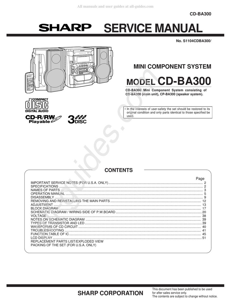
SERVICE MANUAL
SHARP CORPORATION
No. S0167SDNX10///
• In the interests of user-safety the set should be restored to its original
condition and only parts identical to those specified should be used.
This document has been published to be used
for after sales service only.
The contents are subject to change without notice.
The power of this unit is supplied from the amplifying unit via the
system connection cable. It does not operate by itself.
The Service Manual is for the SD-NX10, which is a minor-modification model of the SD-SG11. This manual, therefore, describes only the
changed points from the service manual. Please refer to the SD-SG11 service manual (S9165SDSG11//) together with this manual.
SD-SG11
IMPORTANT SERVICE NOTES (FOR U.S.A. ONLY)........................................................................................................................................ 2
REMOVING AND REINSTALLING THE MAIN PARTS.................................................................................................................................... 15
WIRING PROCESS DIAGRAM ........................................................................................................................................................................ 19
ADJUSTMENT .................................................................................................................................................................................................. 19
ERROR MESSAGE LIST.................................................................................................................................................................................. 29
EEPROM WRITING PROCEDURE .................................................................................................................................................................. 30
DESCRIPTION OF CIRCUIT FOR 1-BIT UNIT ................................................................................................................................................ 32
TO CHECK AND CANCEL PROTECT CIRCUIT DETECTION LINE............................................................................................................... 33
TEST MODE ..................................................................................................................................................................................................... 34
WAVEFORMS OF 1-BIT CIRCUIT ................................................................................................................................................................... 75
WAVEFORMS OF MD CIRCUIT ...................................................................................................................................................................... 76
CD OPTICAL PICKUP LENS CLEANING ........................................................................................................................................................ 78
TROUBLESHOOTING ...................................................................................................................................................................................... 79
FUNCTION TABLE OF IC................................................................................................................................................................................. 83
FL DISPLAY...................................................................................................................................................................................................... 96
CONTENTS
Page
SPECIFICATIONS ............................................................................................................................................................. 2
NAMES OF PARTS ........................................................................................................................................................... 3
OPERATION MANUAL ...................................................................................................................................................... 6
DISASSEMBLY................................................................................................................................................................ 11
NOTES ON SCHEMATIC DIAGRAM .............................................................................................................................. 15
TYPES OF TRANSISTOR AND LED............................................................................................................................... 15
BLOCK DIAGRAM ........................................................................................................................................................... 16
WIRING SIDE OF P.W.BOARD....................................................................................................................................... 23
SCHEMATIC DIAGRAM .................................................................................................................................................. 34
VOLTAGE ........................................................................................................................................................................ 48
FUNCTION TABLE OF IC................................................................................................................................................ 49
PARTS GUIDE/EXPLODED VIEW
PACKING OF THE SET (FOR U.S.A. ONLY)
SD-NX10
MODEL
1-BIT DIGITAL AUDIO SYSTEM
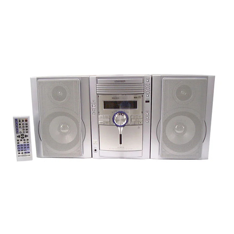
SD-NX10 1-bit Digital Audio System consisting of SD-NX10 (MD/
CD/TUNERunit),SD-NX10(amplifierunit)andCP-NX10(speaker
system).

SD-NX10
– 2 –
FOR A COMPLETE DESCRIPTION OF THE OPERATION OF THIS UNIT, PLEASE REFER
TO THE OPERATION MANUAL.
SPECIFICATIONS
Specifications for this model are subject to change without
prior notice.
SD-NX10
General
Power source AC 120 V, 60 Hz
Power consumption 54 W
Dimensions MD/CD/tuner unit
Width: 12-9/16" (318 mm)
Height: 8-5/16" (210 mm)
Depth: 3-11/16" (93 mm)
Amplifier unit
Width: 6-5/16" (160 mm)
Height: 8-5/16" (210 mm)
Depth: 5-3/8" (136 mm)
Weight MD/CD/tuner unit
8.2 lbs. (3.7 kg)
Amplifier unit
7.7 lbs. (3.5 kg)
Input/output/terminals MD/CD/tuner unit
Auxiliary input: 500 mV/47 kohms
Digital input (optical)
System output (RCA)
Line output: 500 mV/47 kohms
Headphones: 16 - 50 ohms (recommended: 32 ohms)
System control (SD-NX10 amplifier unit only)
Amplifier unit
System input (RCA)
Speakers; 6 ohms
System control (SD-NX10 MD/CD/tuner unit only)
Amplifier
CD player
MiniDisc
Tuner
Amplification system 64fs 1-bit switching
(Remarks:fs = 44.1 kHz)
Output power Power output (FTC):22 watts minimum RMS per chan-
nel into 6 ohms from 20 Hz to 20
kHz, 2 % total harmonic distortion
Rated power output: 25 W + 25 W at 6 ohms, 1 kHz
Frequency response: 20 Hz - 25 kHz (±3dB)
Total harmonic distortion: 0.02% at 1 kHz, 1 W
A/D noise shaping 7th-order (delta - sigma) modulation
Type 1-disc slot-in type compact disc player
Signal readout Non-contact, 3-beam semiconductor laser pickup
D/A converter 1-bit D/A converter
Frequency response 20 - 20,000 Hz
Dynamic range 90 dB (1 kHz)
Type MiniDisc recorder
Signal readout Non-contact, 3-beam semiconductor laser pickup
Rotation speed 400 - 900 rpm CLV, Approx
Error correction ACIRC (Advanced Cross Interleave Reed-Solomon
Code)
Quantization 20-bit linear (A/D converter)
Coding ATRAC (Adaptive TRansform Acoustic Coding),
ATRAC 3
Sampling frequency 44.1 kHz
Recoridng method Magnetic modulation overwrite method
Frequency response 20 - 20,000 Hz
D/A converter 1-bit D/A converter
Wow and flutter Unmeasurable (less than 0.001% W. peak)
Signal/noise ratio 95 dB (1 kHz)
Dynamic range 90 dB (1 kHz)
Audio channel Stereo: 2 channels (SP, LP2, LP4)
Monaural: 1 channel (MONO)
Frequency range FM: 87.5 - 108 MHz
AM: 530 - 1,720 kHz
Type 2-way type speaker system
1-3/16" (3 cm) Tweeter
4" (10 cm) Woofer
Maximum input power: 50 W
Rated input power: 25 W
Impedance 6 ohms
Dimensions Width: 7-3/8" (187 mm)
Height: 16-11/16" (423 mm)
Depth: 7-7/8" (200 mm)
Weight 8.2 lbs. (3.7 kg)/each
CP-NX10

– 3 –
SD-NX10
NAMES OF PARTS
MD/CD/tuner unit front panel
1. CD Eject Button
2. CD Stop Button
3. CD Play/Pause Button
4. CD Fast Reverse/Tuning Down Button
5. CD Fast Forward/Tuning Up Button
6. MD Record Button
7. MD Stop Button
8. MD Play/Pause Button
9. MD Recording Level/MD Fast Reverse Button
10. MD +10 Track Up Button
11. MD Recording Level/MD Fast Forward Button
12. MD Eject Button
13. On/Stand-by Button
14. Tuner (Band) Button
15. Auxiliary/Demo Button
16. MD Record Mode Button
17. Erase Button
18. CD/MD Play Mode Select Button
19. Volume Up and Down Buttons
20. CD/MD Cover Open/Close Button
21. CD Compartment
22. MD Compartment
23. Timer Indicator
24. Sleep Indicator
25. Monaural Recording Indicator
26. Power Indicator
27. Stereo Recording Indicator
28. 2 times Long Recording (stereo) Indicator
29. 4 times Long Recording (stereo) Indicator
30. Remote Sensor
1 2 35 6 8 10 11912
13 1415 16 17 18 19 20
21
23 24 25
2829
27
30
26
22
47
Multi-function LCD display
1. Level Meter/Character Information/Frequency Indicator
2. AM/PM Indicator
3. Top Position Indicator
4. CD/MD Play Indicator
5. Function Indicator
6. Record Indicator
7. MD Record Pause Indicator
8. CD/MD Repeat Indicator
9. Surround Indicator
10. Random Play Indicator
11. Program Play Indicator
12. Sound Synchronized Recording Indicator
13. Track Edit Indicator
14. TOC Indicator
15. FM Stereo Mode Indicator
16. FM Stereo Indicator
17. Sleep Indicator
18. Timer Play/Recording Indicator
1
45
37
6
10
12 13 14
15
16
17
18
11
9
2
8
SD-NX10

SD-NX10
– 4 –
MD/CD/tuner unit rear panel
1. Headphone Jack
2. Digital Input Jack
3. System Control Jack
4. System Output Jacks
5. Line Output Jacks
6. Auxiliary Input Jacks
7. FM 75 Ohms Antenna Jack
8. Antenna Ground Terminal
9. AM Loop Antenna Terminal
Amplifier unit rear panel
1. System Input Jacks
2. System Control Jack
3. Speaker Terminals
4. Cooling Fan
5. AC Input Jack
Amplifier unit front panel
1. Power Indicator
1346789
4
5
13
1
25
2

– 5 –
SD-NX10
1. Speaker Grille
2. Tweeter
3. Woofer
4. Woofer
5. Bass Reflex Duct
6. Speaker Terminals
1
2
3
46
5
Remote control
1. Remote Control Transmitter
2. CD/MD Play Mode Select Button
3. MD Record Mode Button
4. On/Stand-by Button
5. Top Position Button
6. MD Record Button
7. Track Edit Button
8. Sound Synchronize Record Button
9. Volume Up and Down Buttons
10. CD/MD Fast Reverse, Tuning Down Button
11. Extra Bass Button
12. CD/MD Program Button
13. Clear Button
14. Name/TOC-Edit Button
15. Timer/Delete Button
16. Time Button
17. Enter Button
18. MD Stop Button
19. MD Play/Pause Button
20. CD Stop Button
21. CD Play/Pause Button
22. Tuner (Band) Button
23. Auxiliary Input Button
24. Surround Button
25. CD/MD Fast Forward, Tuning Up Button
26. Preset Equalizer Button
27. Character Input/CD, MD, Tuner Direct Buttons
28. Display Button
29. Recording Level/Cursor/Tuner Preset Button
30. CD/MD Edit Button
1
2
3
4
6
*5
*7
*8
9
10
*11
*12
*13
*14
*15
*16
*17
18
19
20
21
22
23
24*
25
26*
27*
28*
29*
30*
Buttons with "*" mark in the illustration can be operated on the remote control only.
Other buttons will operate both the main unit and the remote control.
CP-NX10

SD-NX10
– 6 –
OPERATION MANUAL
Setting the Clock
In this example, the clock is set for 9:30 AM on August 15, 2001.
To confirm the time display:
[When the unit is in the stand-by mode]
Press the DISPLAY button on the remote control.
The time display will appear for about 5 seconds.
[When the power is on]
Press the TIMER/DELETE button.
Within 10 seconds, press the REC LEVEL/CURSOR or button.
The time display will appear for about 10 seconds.
Note:
The clock setting will be cleared when the unit is unplugged or the power failure
occurs.
To reset the clock:
Perform "Setting the Clock" from the beginning.
1Press the ON/STAND-BY button to turn the power on.
2Press the TIMER/DELETE button.
3Within 10 seconds, press the REC LEVEL/CURSOR or buttonto
select the "TIME ADJUST".
4Within 10 seconds, press the ENTER button.
5Press the REC LEVEL/CURSOR or button to adjust the year,
and then press the ENTER button.
6Press the REC LEVEL/CURSOR or button to adjust the month,
and then press the ENTER button.
7Press the REC LEVEL/CURSOR or button to adjust the date,
and then press the ENTER button.
8Press the REC LEVEL/CURSOR or button to adjust the hour,
and then press the ENTER button.
The 12-hour display will appear.
"AM" will change to "PM" automatically.
9Press the REC LEVEL/CURSOR or button to adjust the minutes,
and then press the ENTER button.
The hour will not advance even if minutes advance from "59" to "00".
The clock starts from "0" second. (Seconds are not displayed.) The time display
will disappear after a few seconds.
AM 12:00 is 12 o'clock midnight.
PM 12:00 is 12 o'clock noon.
Error Messages
When an error message is displayed, proceed as follows:
Error messages
Meaning Remedy
BLANK MD Nothing is recorded. (Nei-
ther music nor disc name is
recorded.)
Replace it with another disc.
Can't COPY You tried to record from a
copy prohibited CD. Replace the CD.
Can't EDIT A track cannot be edited. Change the stop position of
the track and then try editing it.
Can't READ* The disc is damaged. Replace it with another disc.
(*: Number or
symbol) TOC information cannot be
read. Erase the disc and try record-
ing again.
MiniDisc not specified.
Can't REC Recording cannot be per-
formed correctly due to vi-
bration or shock in the unit.
Re-record or replace the Mini-
Disc.
Can't T REC Timer recording is impossi-
ble or there is no available
space on the MD.
Replace it with another re-
cordable disc.
The disc is out of recording
space.
Can't WRITE The TOC information could
not be created properly due
to a mechanical shock or to
scratches on the disc.
Set this unit to the stand-by
mode and try to write the TOC
again. (Remove any source of
shock or vibration while writ-
ing.)
CD NO DISC A CD has not been loaded. Load a CD.
The CD data cannot be
read. Reload the CD.
DISC FULL The disc is out of recording
space. Replace the disc with another
recordable disc.
EDIT OVER You chose 21 or more
tracks for track editing. Decrease the number of
tracks.
Er - MD ** A MiniDisc is not working
properly. Press the MD button.
(**: Number or
symbol) Set this unit to the stand-by
mode and turn the power on
again.
Error messages
Meaning Remedy
MD NO DISC A MiniDisc has not been
loaded. Load a MiniDisc.
The MiniDisc data cannot
be read. Reload the MiniDisc.
NAME FULL The number of characters
for the disc name or track
name exceeds 40.
Shorten the disc or track
name.
NOT AUDIO The data recorded on this
disc is not audio data. Replace the disc.
PLAYBACK MD
You tried to record on a
playback-only disc. Replace it with another re-
cordable disc.
POWER ? A MiniDisc is not working
properly. Set this unit to the stand-by
mode and turn the power on
again.
PROTECTED The disc is write protected. Move the write protection tab
back to its original position.
TEMP OVER The temperature is too high. Set this unit to the stand-by
mode and wait for a while.
TOC FORM ** TOC information recorded
on the MD does not match
the MiniDisc specifications
or it cannot be read.
Replace it with another disc.
(**: Number or
symbol) Erase the disc and try record-
ing again.
TOC FULL There is no space left for re-
cording track numbers. Replace it with another re-
cordable disc.
TOC FULL 1 There is no space left for re-
cording character informa-
tion.
Replace it with another re-
cordable disc.
Erase the needless charanc-
ters.
? MD DISC The data contains an error. Press the MD button.
MiniDisc not specified. Replace it with another disc.
– 7 –
SD-NX10
Troubleshooting Chart
Many potential "problems" can be resolved by the owner without calling a service
technician.
General
CD player
MiniDisc
Tuner
Remote control
Symptom Possible cause
"TIME ADJUST" appears when
the clock time is checked. Did a power failure occur? Reset the
clock.
When a button is pressed, the unit
does not respond. Set this unit to the power stand-by mode
and then turn it back on.
No sound is heard. Is the volume level set to "0"?
Are the headphones connected?
Are the speaker wires disconnected?
The picture on the TV screen is
distorted. When a radio or TV which uses an indoor
antennaisplacedneartheunit,thepicture
on the TV screen may be distorted or the
radio may not function properly.
It is recommended that you use an out-
door antenna.
Cannot adjust the volume. Isthesoundconnectioncordconnectedto
the LINE OUT jacks on the MD/CD/tuner
unit? Set the unit to the stand-by mode
andconnectthecordtotheSYSTEMOUT
jacks.
Symptom Possible cause
Even though a disc has been load-
ed, "CD NO DISC" or "Can't
READ" is displayed.
The disc is very dirty.
Is the unit located near excessive vibra-
tions?
Has condensation formed inside the unit?
Playback does not start. The disc is loaded upside down.
Playback stops in the middle or is
not performed properly. The disc does not satisfy the standards.
The disc is distorted or scratched.
Playback sounds are skipped, or
stopped in the middle of a track. Is the unit located near excessive vibra-
tions?
The disc is very dirty.
Has condensation formed inside the unit?
Symptom Possible cause
A recording cannot be made. Is the MiniDisc protected against acciden-
tal erasure?
Did you try to make recording on a play-
back-only MiniDisc?
Can you see the "DISC FULL" or "TOC
FULL" message in the display?
Even though a disc has been load-
ed, "MD NO DISC" or "Can't
READ" is displayed.
The disc is very dirty.
Is the unit located near excessive vibra-
tions?
Playback sounds are skipped. Has condensation formed inside the unit?
Symptom Possible cause
Radio makes unusual noise con-
secutively. The stereo system is placed near the TV
or computer.
FM/AM loop antenna is not placed proper-
ly. Move the AC power cord away from the
antenna if located near.
The preset channel cannot be re-
called. Did a power failure occur?
Preset the channel again.
Symptom Possible cause
The remote control does not oper-
ate. Is the AC power cord of the stereo system
plugged in?
The battery polarity is not correct.
The batteries are dead.
Incorrect distance or angle.
Does the remote control sensor receive
strong light?
Troubleshooting Chart
If trouble occurs (reset)
When this product is subjected to strong external interference (mechanical shock,
excessive static electricity, abnormal supply voltage due to lightning, etc.) or if it is
operated incorrectly, it may malfunction.
If such a problem occurs, do the following:
Unplug the power cord from the AC outlet. Then, plug it in again and retry the
operation.
Caution:
This operation will erase all data stored in memory including clock, timer settings,
tuner preset, and CD or MiniDisc program.
Condensation
Before transporting the unit
Remove the CD and MiniDisc from the unit. Your unit checks whether there are any
discs inside. "NO DISC" appears if no disc is inside. Then, set the unit to the power
stand-by mode. Carrying the unit with discs left inside can damage it.
Sudden temperature changes, storage or
operation in an extremely humid environ-
ment may cause condensation inside the
cabinet (CD pickup, MD pickup, etc.) or on
the transmitter on the remote control.
Condensation can cause the unit to mal-
function.If this happens,leavethepower on
with no disc in the unit until normal playback
is possible (about 1 hour). Wipe off any con-
densationon the transmitterwithasoft cloth
before operating the unit.
Remote Control
Test of the remote control
Check the remote control after checking all connections have been made correctly.
Face the remote control directly to the remote sensor on the unit.
The remote control can be used within the range shown below:
Press the ON/STAND-BY button. Does the power turn on? Now, you can enjoy your
system.
Remote sensor
8" - 20'
(0.2 m - 6 m)

SD-NX10
– 8 –
System connection
cord
×
1
Cable de conexión
del sistema
×
1
“AA”size battery (UM/SUM-3, R6,
HP-7 or similar)
×
2
Pila del tamaño“AA”(UM/SUM-3,
R6, HP-7 o equivalentes)
×
2
Remote control ×1
Controlador remoto
×
1
Sound connection
cord
×
1
Cable de conexión
del sonido
×
1
FM antenna ×1
Antena de FM
×
1
123
Use 2 “AA” size batteries (UM/SUM-3, R6, HP-7 or similar).
Open the
Insert the batteries
Close the
battery cover.
as shown.
battery cover.
1
1
AM loop antenna ×1
Antena de cuadro de AM
×
1
AC power cord
×
1
Cable de alimentación
de CA
×
1
Accessories
Accesorios
Battery installation of remote control
Instalación de las pilas del controlador remoto
2
2
Use dos pilas del tamaño“AA” (UM/SUM-3, R6, HP-7 o equivalentes).
Abra la cubierta
Inserte las pilas
Cierre la cubierta
de las pilas.
como se muestra.
de las pilas.
Speaker wire ×2
Cable del altavoz
×
2
Soft cloth
×
1
Pa
ñ
o suave
×
1
3
3
Right speaker
Altavoz derecho
FM antenna
Antena de FM
AM loop antenna
Antena de cuadro de AM
MD deck, digital tuners
or DAT decks
Grabadora de MD, sintonizadores
digitales o grabadoras de DAT
Connecting cable
for digital recording
(Not supplied)
Cable de conexión
para grabación digital
(No suministrado)
To the optical line
output jack
A la toma de salida
de línea óptica
To the analog
input jacks
A las tomas de
entrada analógica
To the line
output jacks
A las tomas de
salida de línea
RCA cord
(Not supplied)
Cable RCA
(No suministrado)
RCA cord
(Not supplied)
Cable RCA
(No suministrado)
VCR, DVD, etc.
Videograbadora, DVD, etc.
TV
TV
System Connections
Conexiones del sistema

– 9 –
SD-NX10
Clear
Claro
Black line
Línea negra
Left speaker
Altavoz izquierdo
Right speaker
Altavoz derecho
Left speaker
Altavoz izquierdo
AC outlet (AC 120V, 60 Hz)
Toma de corriente de
pared (120 V de CA, 60 Hz)
Plug in with mark facing down.
Enchúfelo con la marca
hacia abajo.
MD/CD/tuner unit
MD/CD/sintonizador
Amplifier unit
Amplificador
Red
Rojo
Red
Rojo
White
Blanco
White
Blanco
Plug in with mark facing up.
Enchúfelo con la marca
hacia arriba.
Caution:
The SYSTEM CONTROL jacks are for the MD/CD/tuner unit and the amplifier unit of SD-NX10 only.
Do not connect to other equipment.
Advertencia:
Las tomas SYSTEM CONTROL son sólo para el MD/CD/sintonizador y el amplificador del SD-NX10.
No las conecte a otros equipos.
4
4
Label side facing you.
Con el lado de la
etiqueta hacia usted
Turn on your System
Conexión de la alimentación de su sistema
Listening to a CD
Audición de un CD
Total number of tracks
Número total de pistas
Total playing time
Tiempo total de reproducción
The first time the unit is plugged in,
the unit will enter the demonstration
mode.You will see words scroll.
Cuando se enchufe por primera vez
el aparato, se establecerá en el
mode de demostración.Verá un
desplazamiento de palabas.
2
1
Press the AUX (DEMO)
button to cancel the
demonstration mode.
Pulse el botón AUX
(DEMO) para cancelar el
mode de demostración.
1
Press the CD button.
2
Press the OPEN/CLOSE button to open the CD/MD cover.
3
Load a CD into the CD compartment, label side facing you.
4
Press the CD button to start playback.
Pulse el botón CD .
Pulse el botón OPEN/CLOSE para abrir la cubierta de CD/MD.
Cargue un CD en el compartimiento del CD,con el lado de la etiqueta hacia usted.
Pulse el botón CD para iniciar la reproducción.
Press the ON/STAND-BY
button to turn the power
on.
Pulse el botón
ON/STAND-BY para
conectar la alimentación.

SD-NX10
– 10 –
1
Press the MD button.
2
Press the OPEN/CLOSE button to open the CD/MD cover.
3
Load a MiniDisc into the MD compartment, label side facing you.
4
Press the MD button to start playback.
Disc name
Nombre del disco
Total number of
tracks
Número total
de pistas
Total playing time
Tiempo total de
reproducción
Label side facing you.
Con el lado de la
etiqueta hacia usted
Listening to a MiniDisc
Audición de un minidisco
Pulse el botón MD .
Pulse el botón OPEN/CLOSE para abrir la cubierta de CD/MD.
Cargue un minidisco en el compartimiento del MD, con el lado de la etiqueta hacia usted.
Pulse el botón MD para iniciar la reproducción.
1Press theTUNER (BAND) button repeatedly to select the desired frequency
band (FM STEREO, FM or AM).
2Press theTUNING ( or ) button to tune in to the desired station.
When the TUNING ( or ) button is pressed for more than 0.5 seconds, scanning will
start automatically and the tuner will stop at the first receivable broadcast station.
3To receive an FM stereo transmission, press the TUNER (BAND) button.
The“STEREO” indicator lights up.
“ST” will appear when an FM broadcast is in stereo.
Listening to the Radio
Audición de la radio
Pulse repetidamente el botón TUNER (BAND) para seleccionar la banda
de frecuencias deseada (FM STEREO, FM o AM).
Pulse el botónTUNING ( o ) para sintonizar la emisora deseada.
Cuandose pulseel botónTUNING( o ) durantemás de0,5segundos,la exploración
se iniciará automáticamente y el sintonizador se parará en la primera emisora difusora
que pueda recibirse.
Para recibir una transmisión de FM en estéreo,
pulse el botón TUNER (BAND). Se encenderá
el indicador“STEREO”.
“ST” aparecerá cuando una difusión de FM sea en estéreo.

– 11 –
SD-NX10
1 Leg Cabinet 1. Screw ..................(A1) x5 11-1
2 Rear Panel 1. Screw ..................(B1) x9 11-1
2. Screw ..................(B2) x1
3
MD/CD Lid Cabinet/
1. Open it in the direction of 11-2
Loading Gear Ass'y
the arrow.
* (Note 1) 2.
Lid Cushion Cover ...
(C1) x2
3.
Screw Cover Sheet..
(C2) x1
4. Screw ................. (C3) x5
5. Rear Support Bracket
.................................(C4) x1
6. Socket ................ (C5) x3
4 Front Cabinet 1. Screw ................. (D1) x5 11-2
2. Socket ................ (D2) x2 11-3
3. Tip ...................... (D3) x1
5 Main PWB 1. Screw ..................(E1) x6 11-3
2. Socket .................(E2) x7
3. Flat Cable............(E3) x3
6 MD/CD Block 1. Screw .................. (F1) x5 12-1
2. Socket ................. (F2) x2 12-2
7 Tuner Unit 1. Screw ................. (G1) x3 12-2
8 Jack PWB 1. Screw ................. (H1) x6 12-2
9 MD Sensor PWB 1. Screw .................. (J1) x1 12-3
10 OPEN/CLOSE 1. Screw ..................(K1) x1 12-3
Switch PWB
11 LED A/B PWB 1. Hook.................... (L1) x2 12-4
2. Screw .................. (L2) x4
12 Front Decoration 1. Screw ................. (M1) x8 12-4
Panel
13 Top Cabinet 1. Screw ................. (N1) x3 12-5
14
MD/CD Switch PWB
1. Screw ................(P1) x10 12-5
15 Socket PWB 1. Screw ................. (Q1) x2 12-6
16
CD Mechanism Ass'y
1. Screw ................. (R1) x4 12-6
17
MD Mechanism Unit
1. Screw ..................(S1) x4 12-6
18 MD Mechanism/ 1. Screw .................. (T1) x8 13-1
MD Main PWB 2. Flat Cable............ (T2) x3
* (Note 2) 3. Flexible PWB ...... (T3) x1
4. Socket ................. (T4) x2
DISASSEMBLY
STEP REMOVAL PROCEDURE FIGURE Figure 11-1
Caution on Disassembly
Follow the below-mentioned notes when disassembling
the unit and reassembling it, to keep it safe and ensure
excellent performance:
1. Take compact disc and minidisc out of the unit.
2. Be sure to remove the power supply plug from the wall
outlet before starting to disassemble the unit.
3.Take off nylon bandsor wire holders wherethey need to
beremovedwhendisassemblingtheunit.Afterservicing
theunit, be sure torearrange the leadswhere they were
before disassembling.
If the screw of the wrong length is applied on the MD
mechanism unit (screw for mounting parts to the MD
mechanism chassis), it may contact the optical pickup
and cause the unit to malfunction.
4. Take sufficient care on static electricity of integrated
circuits and other circuits when servicing.
SD-NX10 (MD/CD/TUNER UNIT)
* (Note 1)
Screws are covered. Remove the cushion covers first with a sharp-
ended stick and then screws.
Be careful not to damage them when removing. They will be reused.
* (Note 2)
After pulling out the optical pickup connector, wrap the tip of it with
conductivealuminium foil or the liketo protectthe optical pickupfrom
the static electricity.
Figure 11-2
Figure 11-3
Rear Panel
Front Cabinet
Leg Cabinet
(B1)x9
ø3x10mm
(B2)x1
ø3x8mm
(A1)x5
ø3x10mm
(D1)x3
ø3x10mm
(C3)x1
ø3x10mm
(C3)x2
ø3x10mm
(C3)x2
ø3x10mm
(C1)x2
(D1)x2
ø3x10mm
Socket
PWB
Loading Gear
Ass'y
MD/CD Lid
Cabinet
(C2)x1
(C4)x1
(C5)x3 CD Mechanism
Ass'y
MD Mechanism
Unit Front
Cabinet
(E1)x6
ø3x8mm
(D2)x1
(E2)x2
Main PWB
Main PWB
Jack PWB
(E2)x1
(E3)x1
Main PWB
Jack PWB Jack PWB
(D2)x1
(E3)x1
(E3)x1
(D3)x1
(E2)x1
(E2)x1
(E2)x2

SD-NX10
– 12 –
Figure 12-1
Figure 12-2
Figure 12-3
Figure 12-4
Figure 12-5
Figure 12-6
CD Mechanism
Ass'y
MD/CD
Block
MD Mechanism
Unit
(F1)x1
ø3x8mm
(F1)x1
ø3x8mm
(F1)x3
ø3x10mm
Tuner Unit
Jack PWB
(H1)x3
ø3x8mm
Lug
Wire (H1)x1
ø3x10mm
(H1)x2
ø3x10mm
(G1)x3
ø3x8mm
(F2)x1
(F2)x1
OPEN/CLOSE
Switch PWB
MD/CD Lid
Cabinet
MD Sensor
PWB
(J1)x1
ø2.6x8mm
(K1)x1
ø2.6x8mm
Front
Cabinet
Front Aluminium
Decoration Panel
Lighting
Plate
LED B PWB
LED A
PWB
Lug Wire
(M1)x1
ø3x6mm
(M1)x1
ø3x6mm
(L1)x1
(L1)x1
(M1)x6
ø3x6mm
(L2)x4
ø3x10mm
Front
Cabinet
Top
Cabinet
(N1)x3
ø3x10mm
(P1)x5
ø3x10mm
(P1)x5
ø3x10mm
CD Switch
PWB
MD Switch
PWB
Socket PWB
Lug Wire
MD Mechanism
Unit
CD Mechanism
Ass'y
(S1)x2
ø3x10mm
(Q1)x2
ø3x10mm (S1)x2
ø3x10mm
(R1)x2
ø3x10mm (R1)x2
ø3x10mm
MD/CD
Block

– 13 –
SD-NX10
Figure 13-1
Figure 13-2
Special driver
(Amplifier unit: aluminium decorative plate)
To prohibit users' disassembling the unit, special screws are
used to fix the decorative plate. A special driver is required.
Figure 13-4
Special driver bit
(Torque head: T8 type)
1 Leg Cabinet 1. Screw..................(A1) x5 13-3
2 Rear Cabinet 1. Screw................(B1) x11 13-3
3 Front Cabinet 1. Screw................. (C1) x6 13-4
4 Rear Panel 1. Screw................. (D1) x6 14-1
2. Socket................ (D2) x1
5 1-Bit Amp. Unit 1. Screw..................(E1) x2 14-1
2. Socket.................(E2) x4
6 Terminal PWB 1. Screw.................. (F1) x2 14-2
2. Socket................. (F2) x2
7 Power/Power LED 1. Screw................. (G1) x2 14-2
PWB 2. Socket................ (G2) x2
8 Shield Cover 1. Screw............... (H1) x12 14-3
2. Heat Sink ........... (H2) x1
3.
1-Bit Amp. Bracket ..
(H3) x1
9 1-Bit Amp. PWB 1. Screw.................. (J1) x4 14-4
STEP REMOVAL PROCEDURE FIGURE
SD-NX10 (AMPLIFIER UNIT)
Figure 13-3
(T2)x2
(T1)x1
ø
2x2mm
(T1)x1
ø
2x3mm
(T1)x1
ø
2x3mm
(T1)x1
ø
2x3mm
(T1)x1
ø
2x3mm
(T2)x1
(T4)x1
(T4)x1
(T1)x1
ø
2x3mm
(T1)x2
ø
1.7x3mm
Shield Case, Bottom
(T3)x1
Optical pickup
Flexible PWB (*1)
Pull
Pull
MD Main PWB
MD Mechanism
Shield Case, Side
Shield Case, Top
(*1) After pulling out the flexible
PWB for the optical pickup,
wrap its tip with conductive
aluminium foil or the like to
protect the optical pickup from
the static electricity.
(A1)x5
ø3x10mm Front Cabinet
Rear Cabinet
Leg Cabinet
(B1)x1
ø3x10mm
(B1)x3
ø3x10mm
(B1)x5
ø3x10mm
(B1)x1
ø3x8mm
(B1)x1
ø3x10mm
(C1)x2
ø3x8mm
(C1)x2
ø3x8mm
Front Cabinet
(C1)x2
ø3x10mm
Washer

SD-NX10
– 14 –
Figure 14-1
Figure 14-2
Figure 14-4
Figure 14-3
(D1)x2
ø3x8mm
(D1)x1
ø3x10mm
(D1)x3
ø3x8mm
(E2)x1
(E2)x1
(E2)x1
(E2)x1
(D2)x1
(E1)x2
ø3x8mm
Power
PWB
Power
PWB
Terminal
PWB
Rear
Panel
1-Bit Amp.
Unit
Power Trans
PWB
(G1)x1
ø3x10mm
(G1)x1
ø3x8mm
(F1)x2
ø3x8mm
(G2)x2 (F2)x2
Power
PWB
Terminal
PWB
Power LED
PWB
Main Chassis
Power Trans
PWB
Power PWB
Terminal
PWB
(H1)x2
ø3x8mm
(H1)x1
ø3x6mm
(H1)x1
ø3x6mm
(H1)x1
ø3x6mm
(H1)x1
ø3x8mm
(H1)x4
ø3x8mm
(H1)x1
ø3x6mm (H1)x1
ø3x8mm
(H3)x1
(H2)x1
Washer
Washer
Shield
Cover
(J1)x4
ø3x10mm
1-Bit Amp.
PWB
Be careful of the
silicon grease.
1 Woofer 1. Leg Cushion ........(A1) x4 14-5
2. Screw ..................(A2) x4
3. Top Cover ...........(A3) x1
4. Front Panel .........(A4) x1 14-6
5. Screw ..................(A5) x8
2 Tweeter 1. Screw ..................(B1) x4 14-6
STEP REMOVAL PROCEDURE FIGURE
CP-NX10
Figure 14-5
Figure 14-6
(A2)x4
ø4x16mm
(A1)x4
Screwdriver
(A3)x1
Front Panel
Top Cover
Leg Cabinet
(A5)x4
ø4x40mm
(A5)x4
ø4x40mm
(B1)x4
ø4x12mm
Woofer
Tweeter
(A4)x1

– 15 –
SD-NX10
•Schematic diagram and Wiring Side of P.W.Board for this
model are subject to change for improvement without prior
notice.
•The indicated voltage in each section is the one measured
by Digital Multimeter between such a section and the chas-
sis with no signal given.
1. In the tuner section,
( ) indicates AM/FM stereo
2. In the CD section, the CD is stopped.
•Parts marked with “ 1” ( ) are important for
maintaining the safety of the set. Be sure to replace these
parts with specified ones for maintaining the safety and
performance of the set.
NOTES ON SCHEMATIC DIAGRAM
•Resistor:
To differentiate the units of resistors, such symbol as K and
M are used: the symbol K means 1000 ohm and the symbol
M means 1000 kohm and the resistor without any symbol is
ohm-type resistor. Besides, the one with “Fusible” is a fuse
type.
•Capacitor:
To indicate the unit of capacitor, a symbol P is used: this
symbol P means pico-farad and the unit of the capacitor
without such a symbol is microfarad. As to electrolytic
capacitor,theexpression“capacitance/withstandvoltage”is
used.
(CH), (TH), (RH), (UJ): Temperature compensation
(ML): Mylar type
(P.P.): Polypropylene type
SW1930 WRITE PRO ON—OFF
SW1931 DISC MEDIA ON—OFF
SW1932 LOADING ON—OFF
SW1933 RECORD ON—OFF
SW1934 PLAY ON—OFF
SW1936 LEAD IN ON—OFF
SWD02 ON/STAND-BY ON—OFF
SWD03 TUNER (BAND) ON—OFF
SWD04 AUX (DEMO) ON—OFF
SWD05 CD FAST FORWARD/TUNING UP ON—OFF
SWD06
CD FAST REVERSE/TUNING DOWN
ON—OFF
SWD07 CD PLAY/PAUSE ON—OFF
SWD08 CD STOP ON—OFF
SWD09 CD EJECT ON—OFF
REF. NO DESCRIPTION POSITION POSITIONREF. NO DESCRIPTION
SWD10 MD +10 TRACK UP ON—OFF
SWD11 VOLUME DOWN ON—OFF
SWD12 VOLUME UP ON—OFF
SWD13 CD/MD COVER OPEN/CLOSE ON—OFF
SWD14 MD REC ON—OFF
SWD15 MD STOP ON—OFF
SWD16 MD PLAY/PAUSE ON—OFF
SWD17 MD DOWN ON—OFF
SWD18 MD UP ON—OFF
SWD19 MD EJECT ON—OFF
SWD20 PLAY MODE ON—OFF
SWD21 ERASE ON—OFF
SWD23 OPEN/CLOSE ON—OFF
SWD24 REC MODE ON—OFF
TYPES OFTRANSISTOR AND LED
2SA1162 G
2SD601 AR
KRA225 S
KRC102 S
UN2113
UN2213
UN2214
UN221 N
DS1SS133
2SA02M
B
(3)
E
(1)
C
(2)
TOP
VIEW
SB00703Q
SBE803
TOP VIEW
TOP VIEW
TOP VIEWTOP VIEW
2SC2878 B
2SK246 GR
KTA1023 Y
KTA1266 GR
KTA1271 Y
KTA1273 Y
KTC3199 GR
KTC3203 Y
KRA106 M
KRA107 M
KRC104 M
KRC107 M
VIEW
FRONT
E C B
(S)(G)(D)
(1)(2)(3)
DS1N404S
1SS355
543
21
1:Cathode
2:Cathode
3:Anode
4:No Contact
5:Anode
2SA1314 C
FRONT
VIEW
BCE
TS4B03GM
AC AC
VIEW
FRONT
FRONT
VIEW
2647RT49
4204UYT9
4204UGT9
2SB1205
FRONT
VIEW
B
C
EDB3804X
LNG901CF

SD-NX10
– 16 –
Figure 16 BLOCK DIAGRAM (1/7)
TO TUNER UNI
T
TUN1
LEDD01
LEDD02
PHCU01
CNPU06
LEDD03
LEDD04
LEDD05
LEDD06
LEDD14
∆∑
LEDD13
LEDD15
LOAD_M+
LED12
LED4
LED2
LED1
LED12 LOAD_M–
CD_SENS_B
CD_SENS_A
LOAD_M-
CD_SENS_C
BUS0
BUS2
CD_RESET
MD
_
LED5
LED1
CCE
BUCK
DO
DI
CE
POWER
LCK2
LCK1_
BUS2
CD_SENS_A
DR_M+
LED6
DO
LCK1_
CLK
DI
MD
_
MD
_
MD
_
MD
_
TUNER_SM
LED4
LED7
DR_M–
DR_CL_IN MD
_
MD
_
MD
_
CLK
CE
DI
LINE_MUTE
DATA
CLOCK
CLK
SYS_MUTE
TUN_MUTE
DR_M+
DR_M–
LOAD_M+
MD_DISC_IN
DR_CL_IN DR_OP_INDR_OP_IN
MD_DISC_IN
LED5
LED6
LED7
BUS1
BUS3
BUS0
CD_SENS_C
SUR_ON/OFF
CD_FUNC
TUN_L
CCE
CD_CHK_SW
BUS1
BUCK
BUS3
CLK
TUNER_SM
CD_SENS_B
LED2
CD_CHK_SW
LED3
LED3
+B7(+12V)
+B5(5V SWD)
V
RES
E
SYS
HP_
PR
O
TUN_ST/SD
QD09
QD10
+B4(8V)
+B11(5V CD)
ICD02
BU2092F
INPUT/OUTPUT
EXPANDER
+B12(5V)
ICU03
TA7291S
LOADING MOTOR
DRIVER
+B4(8V)
VS
+B12(5V)
ICD03
BU2092F
INPUT/OUTPUT
EXPANDER
+B7(12V)
+B5(5V)
POWER
QD11
QD05
QD04
QD03
SP
LP2
LP4
MONO
BLUE
GREEN
RED
RED
GREEN
BLUE
SLEEP
MD DISC
IN SW
M
M904
MD/CD LID
MOTOR
–
+
OPEN
CLOSE
VSS
AVSS
VEE
VCC
VREF
CD RESET
INVERTER
QD01
+B12
TIMER_LED
VP
X-IN
X-OUT
VF1
+B13(5V)
BACK UP
+B5(+5V)
FLD01
~~
~ 8.3886MHz
XLD01
~
RMD01
REMOTE
SENSOR
KEY
SWD02~SWD21
SWD24
ICD01
IX0463AW
SYSTEM MICROCOMPUTER
1
15
47
44
43
3
6
5
3 7
1
8
2
12 13 14 23 24 25 26 27 28 29 46
4
2
1
2
3 32
9 373633 41 45
31
6 42
10
14
13 3
5
8
4
1
18
2
6
15
16
5 2 134
26 22 2124 2325 20 19 18 9 7
13 12 11 1017
9
11
1
39 40
6 54 59
38
48 90 92 97 9891
100
10
9
7
11
5 18
6
8
16
16 15 14 68 9
14 6
12
15 11 7
13 8
10
1
3
4
2
22
21
20
19
18
17
16
7
35
34
10
99
SWD23
OPEN/CLOSE
TO CD SERVO PWB UNIT
LED DRIVE
LED DRIVE
LED DRIVE
LED DRIVE
BUFFER
BUFFER

– 17 –
SD-NX10
Figure 17 BLOCK DIAGRAM (2/7)
TO MD SECTION
TO TUNER UNIT
TUN1
CNPU04
CNSU03
CNSU01
CNPU09
CNPU08
CNPU07
RU20
CNPU05 CNSU02
MD_LOADSW
MD_SERCH
MD_DSCK
MD_DATA_
MD_RESET
MD_ST
MD_KDATA
POWER
MD_D_STB_
POWER
CD_FUNC
MD_LOADSW
LINE_MUTE
R_AUX_IN
L_AUX_IN
L__REC_OUT
R__REC_OUT
R_PRE_OUT
L_PRE_OUT
DO
TUN_MUTE
LCK2
LCK1_
DO
MD_SERCH
MD_D_STB_
MD_KDATA
MD_ST
LRCK
DATA
BCCK
MD_RESET
MD_DSCK
MD_DATA_
CE
TUN_R
TUN_L
CD_FUNC
TUNER_SM
DATA
LRCK
BCCK
DI
CLK
LCK2
HP_SW
PROTECT
CD_FNUC
POWER
R_H/P_OUT
L_H/P_OUT
+B13(5V)
BACK UP
+B12(5V) +B3(5.6V USWD)
+B7(+12V)
+B5(5V SWD)
VF2
VF1
–VP
+B8(6V)
+B6(5V)
+B5(5V SWD)
+B3(5.6V USWD)
SYSTEM_MUTE
QP03
QP04
QP05
+B4(8V)
+B11(5V CD)
–B2(–12V)
+B7(+12V)
VF2
SURROUND
AMP. ICP01
NJM4580M
BUFFER AMP.
+B3(5.6V USWD)
CD DIGITAL SIGNAL
ALC
QP11~
QP14
+B7
(+12V)
–B2
(–12V)
+VCC
–VCC
R-CH
L-CH
RESET
STOPSYSTEM
HP_SW
PROTECT
TUN_ST/SD
ICE04
PST9140
RESET
QD06
RESET
SYSTEM STOP
QP09
QP01
QP02
SYSTEM_MUTE
QS02
QS01
SURROUND
ON/OFF
L-CH
R-CH
–VCC +VCC
+B7
(+12V)
–B2
(–12V)
L-CH
R-CH
L-CH
R-CH
SURROUND
ICS01
NJM4580M
RL
+B7(12V)
DIG-IN
GND
+B11(5V CD)
VOLTAGE
REGULATOR
+B11(5V CD)
+B5(5V SWD)
VOLTAGE
REGULATOR ICU02
74VHC00F
INVERTOR
ICU04
74VHC08F
INVERTOR
ICU05
LC89051V
DIGITAL AUDIO
INTERFACE
NCNC
BASS TRE
MD/CD
AUX
TUNER
L
L
L
R
R
R
CE
DI
CLK
SELO
GND
REC
OUT
ICU01
LC75341M
AUDIO
PROCESSOR
+B6(5V)
+B8(6V)
DIG-OUT
DIG-IN
D-GND
BACKUP
PDOWN
RESET
MD-ST
DSCK
SERCH
KDATA
MDDATA
DSTB
D-GND
D-GND
D-GND
D-GND
D-VDD
D-VDD
PCONTO
LOADSW
A-VCC
AA-GND
AD-GND
TO MD SECTION
L_IN
R_IN
R_OUT
L_OUT
GND(A)
VEE
VCC
VP
+B13(5V)
BACK UP
123456789
10111213141516171819202122232425262728
12
12
2
4
6
8
3
3
1
3
9
10
11
15
1
3
5 7
4 8 1
14
5
6
7
3
8
4
7
2
16
5
14
5
8
12
12
4
1
23 21
8
4
22
5
24
12 13 1
14 3
6
11
1
3
2
4
3
2
1
1
2
3736 41 45
59 57
9891
459 26 1
12
11 7 38
10
22
21
20
19
18
17
16
2
24
1
8
17
12 13
01
15
14
11
5 20 19
6
21
4
16
9
3 23
5
3 8
4
1
7
2 6
7
35
34
10
13
15
18
7
10
19
17
8
6
5
1
4
12
13
9
11
2
TO POWER
SECTION TO CD
SECTION
TO POWER
SECTION
TO POWER
SECTION
TO POWER
SECTION
SURROUND
SWITCHING BUFFER
MUTE
DRIVE
RESET
DRIVE

SD-NX10
– 18 –
Figure 18 BLOCK DIAGRAM (3/7)
T601
POWER TRANSFORMER
CNP601
CNP602
CNP603 JTP01
SYSTEM OUT/
LINE OUT/AUX IN
TERMINAL
IC650
TORX178A
DIGTAL IN
3
2
1
PROTECT
HP_SW
LCK2
CLK
DI
LINE_MUTE
CD_FNUC
R__REC_OUT
L__REC_OUT
L_AUX_IN
R_AUX_IN
L_H/P_OUT
POWER
L_PRE_OUT
R_PRE_OUT
R_H/P_OUT
S3_2
PROTECT_
DI_
CLK_
LCK2_
POWER_
S3_1
SO 605
SYSTEM
CONTROL
TERMINAL
+B5(5V SWD)
TO MAIN SECTION MAIN SECTION
GND(D)
D-OUT
TO MAIN SECTION
–B2(–12V)
+B7(+12V)
+B8(6V)
+B5(5V SWD)
+B11(5V CD)
VF2
VF1
–VP
QP07
QP08
QP06
BI650
+B7(+12V)
–B2(–12V)
+B4(8V)
+B3(5.6V USWD)
+B5(5V SWD)
+B6(5V MD)
+B8(6V MD)
–VP
VF1
VF2
+B11(5V CD)
R-CH
L-CH
AUX IN
LINE OUT
L-CH
R-CH
SYSTEM OUT
R-CH
L-CH
TO MAIN SECTION
JHP01
HEADPHONES
Q603
Q606
Q605
+B4(8V CD)
IC601
KIA7812AP
VOLTAGE
REGULATOR
IC602
KIA7805AP
VOLTAGE
REGULATOR
+B4(8V CD)
(5.6V USWD)
+B3
+B6(5V MD)
VOLTAGE
REGULATOR
VOLTAGE
REGULATOR
Q602
Q601
D601-D604
VOLTAGE
REGULATOR
VOLTAGE
REGULATOR
5
2
8
3
7
1
6
4
15
2
7
18
13
11
9
13
12
4
1
5
6
8
17
19
10
16
7
4
6
5
14
1
11
10
9
3
3
8
2
12
1
2
3
1
2
3
2 6
1
2
4
5
3
13
1
3
12
3
11
8
7
9
2
1
10
BUFFER MUTE
DRIVE
PROTECT
DRIVE
5V CD
SWITCHING

– 19 –
SD-NX10
Figure 19 BLOCK DIAGRAM (4/7)
IN
NF–OUT–
OUT+ NF+
ICA100
IX2815AF
7TH ORDER ∆∑ MODULATION
CONVERSION LSI
OUTPUT OFFSET
ADJUSTMENT
ANALOG SIGNAL
INPUT
- POWER
- POWER
- POWER
+POWER
+POWER
LOAD
OUTPUT FET
+5 V
GND
REF
POWER -
LEVEL SHIFT
GATE DRIVER
LOW PASS
FILTER
-9V with reference to
the minus voltage
OUT
ICA105
NJM78M09
+9 V VOLTAGE
REGULATOR
IN
NF
GND
L-IN
L-OUT
H-OUT H-IN
L-IN
L-OUT
H-OUT H-IN
B. S
B. S
+5 V
DEAD TIME
CONTROL
SLICE LEVEL
SET VOLTAGE

SD-NX10
– 20 –
Figure 20 BLOCK DIAGRAM (5/7)
SOV90
SYSTEM CONTROL
TERMINAL
ICV99
KIA4558P
OPE AMP.
8
7
6
5
4
3
2
1
CNP802
JT900
SYSTEM IN
TERMINAL
RL800
IC807
KIA7810AP
VOLTAGE
REGILATOR
3
2
1
CNP801
D811
D810
IC800
AN78L05
VOLTAGE
REGULATOR
3
2
1
IC805
AN78L05
VOLTAGE
REGULATOR
3
2
1
IC806
KIA7805AP
VOLTAGE
REGULATOR
3
2
1
D812
CNPV98
IC801
KIA7810AP
VOLTAGE
REGULATOR
3
2
1
IC804
KIA7805AP
VOLTAGE
REGULATOR
3
2
1
IC802
KIA7808AP
VOLTAGE
REGULATORP
3
2
1
QV99
Q
V
QV95
QV98
QV96
Q803
+B10
+B9
CNPV99
+8V(CD)
+11.2V
+5V(MD)
+B6
+B4
–B1+B1
+B1
+B6
+B4
+B3
+B10
+B9
–B1
+B2
R-CH
L-CH
TO 1BIT AMP SECTION
TO 1BIT AMP SECTION
TO 1BIT AMP
SECTION TO 1BIT AMP
SECTION
GND
L
R
POWER
+5V_MD
PROTECT
5.6V_UNSW
LCK
+8V_CD
CLK
DI
S3-2
S3-1
D_+5V
A_GND
A_+5V
D_GND
AD Reset
V+
+
V–
– +–
2
1
3
4
5
1
3
2
3
21
DC DETECT DC DETEC
T
PROTECT
DRIVE
+B
RELAY
DRIVE
Table of contents
Other Sharp Stereo System manuals

Sharp
Sharp CD-SW300 User manual

Sharp
Sharp DK-KP95PH User manual

Sharp
Sharp CD-ES770 User manual

Sharp
Sharp XL-1600 User manual

Sharp
Sharp QT-CD180H User manual

Sharp
Sharp CD-C491H User manual

Sharp
Sharp CD-E110H User manual

Sharp
Sharp XL-45H User manual

Sharp
Sharp CD-C1800 User manual

Sharp
Sharp CD-BA150 User manual

Sharp
Sharp CD-M4000W User manual

Sharp
Sharp CD-DP900H User manual

Sharp
Sharp CD-XP250E User manual

Sharp
Sharp MD-E9000H User manual

Sharp
Sharp CD-SW440NH User manual

Sharp
Sharp CP-X99 User manual

Sharp
Sharp CD-E600H User manual

Sharp
Sharp CD-G20000 User manual

Sharp
Sharp XL-MP60 User manual

Sharp
Sharp CD-C250X BK User manual