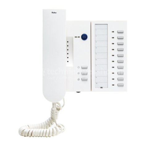
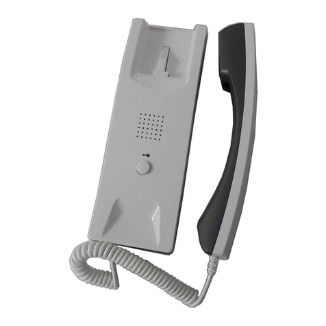
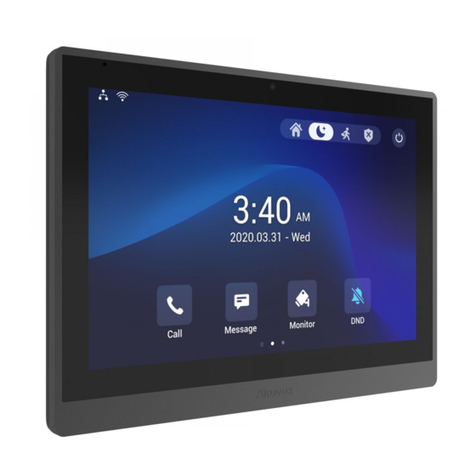
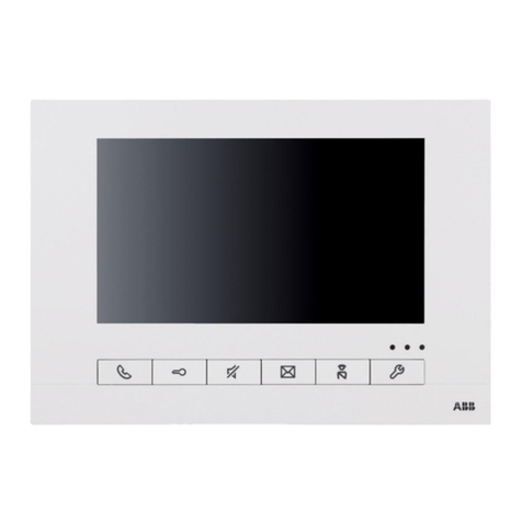
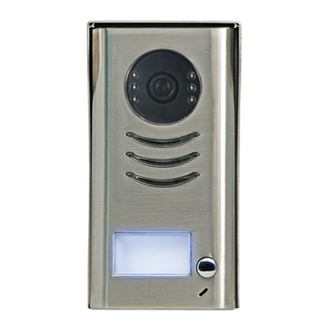
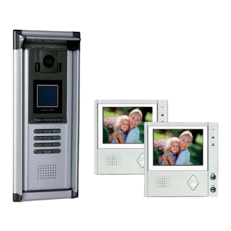
Shideantec SD-880RC16-DC1001 User manual

1
1
2
3
4
5
5
7
SD-880RC16-DC1001
VER A0
Manual
CATALOGUE
Precautions
Parts in the package
Names of each part and functions
Operation instructions
Installation instructions
Specification
Wiring
How to correct the usual faults

SD-880RC16
SD-880RC16-1
SD-880RC16-2
SD-880RC16-3
SD-880RC16-4
VERA2.0
ManualInstruction
Features
Namesofeachpartandthefunctions
Installationillustration
Specifications
Howtocleartheusualfaults
Operationnotes
OperationInstructions
Wiring
1
2
5
7
10
10
11
12
CATALOGUE
SD-880RC16-1
SD-880RC16-2
SD-880RC16-3
SD-880RC16-4
VER A2.0
Manual Instruction
Features
Namesof each part and the functions
Installationillustration
Specifications
Howto clear the usual faults
Operationnotes
OperationInstructions
Wiring
1
2
5
7
10
10
11
12
CATALOGUE
Outdoor
station
Manual
Other
Accessaries
Screws
Bracket
Indoor
monitor
WARNING CAUTION
Please read thismanual carefully before installation andoperation to avoidany
damage and loss.
(1)Only professionalengineer is qualifiedfor
the wiring work.
(2)Do notdisassemble or replaceany parts
without authorization fromthe manufac-
turer.
(3)Except productsapproved by themanuf-
acturer, do notmatch it with products of
other manufacturers.
( )Toavoid fire andelectric shock, donot
expose it torain or humidity.
(1)Keep thesurface clean. Donot wash it with
water directly.Do not wipewith chemical
solvent like thinner,benzene and petrol.
(2)Keep thedevice away fromrain and hum-
idity.
(3)Do notinstall it atplace of high temperature
or under directsunshine. Standard operation
temperature is -10
(4)Do notsmash or strike the device withfists
or other sharpand hard objects, nor hit other
articles with it.
(5)Installation instrong magnetic field area is
strictly prohibited.
(6)Installation near broadcaststation or antenna
may cause signalinterference.
Parts in the package :
1

2
Outdoor station SD-880DC1001
outdoor station SD-880DC1001-H
4P LINES
Red (R4)
:
VCC
Black (R2)
:
GND
VIDEO
Brown (R1)
:
White (R3)
:
AUDIO
4P LINES
Microphone
Pick up the voice
of the visitor.
Speaker
Broadcast the
voice from the host
Camera
Pick up the image of
the visitor clearly.
Terminals function:
Call button
Chime "ding dong"
sound can be heard
from inter-phone,when
the button is pressed,
the camera works
simultaneously.
Fore view
Rear view
Camera
Pick up the image of
the visitor clearly.
Speaker
Broadcast the
voice from the host
Microphone
Pick up the voice
of the visitor.
Fore view
Rear view
Red (R4)
:
VCC
Black (R2)
:
GND
VIDEO
Brown (R1)
:
White (R3)
:
AUDIO
Terminals function:
Call button
Chime "ding dong" sound can
be heard from inter-phone,when
the button is pressed, the camera
works simultaneously.
Super Bright LEDs
Let you see
clearly even
at night.
Super Bright LEDs
Let you see
clearly even
at night.
Indoor monitor SD-880RC16
1
23
4
5
8
7
11
10
9
6

3
1.Handset
Lift to communicate with your visitors.
2.Monitor Screen
Color LCD-TFT
3.Power Lamp(Red)
Indicate if the system is on or off.
4.Operate Lamp(Red)
Light on indicates operation.
5.Unlock Lamp(Red)
Light on indicates unlocked E-lock.
6.Monitor Button
Press this button to view the picture
from the camera.
7.Call Button
Press this button to realize the inter
-communication when two or more
indoor monitor are installed.
8.Door Release Button
9.Volume
10.Brightness
11.Contrast
How to operate when ringing:
Chime "ding dong"
sound can be heard
from the indoor monitor
when the visitor press
"Call" button. button,
and picture appear
simultaneously.
Pick up the handset to
communicate with the
visitor, put
down to end
communication and
monitor be switched
off simultaneously.
Hang up the handset
when confirm, and
press "Unlock" button
to release the door.
Auto off in 30 seconds W/O
communication.
OFFOFF
7575
R1
R2
R3
R4
L+
L-
R1
R2
R3
R4
L+
L-
R1
R2
R3
R4
L+
L-

4
Communicate with outdoor statione:
Hang up the
handset to end
communication,
and monitor auto
off simultaneously.
Pick up handset
and press "Monitor"
button to communicate
with visitor, and image
auto on simultaneously.
Monitor
Hang up the
handset to switch
off monitor, or
auto off in 30
seconds.
Press "Monitor"
button, picture
from the camera
appears.
1. Connect
the 4-cords to the terminals back of outdoor
station (W/ polarity)
2. Fasten outdoor station to
3. Fasten the screws as the picture shows
Fasten rain cover on the wall
rain cover
1. Connect
the 4-cords to the terminals back of outdoor
station (W/ polarity)
2. Fasten outdoor station to
3. Fasten the screws as the picture shows
Fasten rain cover on the wall
rain cover

5
1. Fasten the bracket onto the wall by screws
2. Connect the 4-cord to the terminals back
of indoor monitor (W/ polarity)
3. Fasten the indoor monitor onto the bracket
4. Connect the spring wire of handset
5.Put the plug into the power socket.
0.1 LUX
SD-880DC1001
0.1LUX
142(L) 53.5(W) 40(H)mm
SD-880DC1001-H
1/3" CCD/CMOS 1/3" CCD/CMOS
F3.6mm 78 angle F3.6mm 78 angle
AC 100-240V(&DC 15V)
LCD-TFT display
420TV lines
Chime "ding dong" sound
25W MAX
185(L) 210(W) 57(H)mm
SD-880RC16
Camera
Lens and angle
Min. Illumination
Light source
Dimension
Outdoor station
Indoor monitor
Power source:
CRT:
Resolution:
Calling music:
Power consumption:
Dimension:
4 Super Bright LEDs
1. Wiring as attached pictures when 1, 2 or 3 indoor monitor.
2. If 1 indoor monitor, switch on the image impedance matching switch.
If 2 or 3 indoor monitor, switch on only the second or the third (as attached picture).
3. For clearer picture, please use 75W 5C2V coax cable for connecting
terminal No.1(video)and No.2(ground) between outdoor station and indoor monitor,
2
RVV3X16/0.15W/0.3mm cut area.
4 Super Bright LEDs
VIDEO
Brown (R1)
:
Black (R2)
:
GND
White (R3)
:
AUDIO
Red (R4)
:
VCC
OFFOFF
7575
R1
R2
R3
R4
L+
L-
R1
R2
R3
R4
L+
L-
VIDEO
Brown (R1)
:
Black (R2)
:
GND
White (R3)
:
AUDIO
Red (R4)
:
VCC
OFFOFF
7575
R1
R2
R3
R4
L+
L-
R1
R2
R3
R4
L+
L-
OFFOFF
7575
R1
R2
R3
R4
L+
L-
R1
R2
R3
R4
L+
L-
R1
R2
R3
R4
R1
R2
R3
R4
R1
R2
R3
R4
58.5(W) 134.5(L) 40(H)mm

6
VIDEO
Brown (R1)
:
Black (R2)
:
GND
White (R3)
:
AUDIO
Red (R4)
:
VCC
OFFOFF
7575
R1
R2
R3
R4
R1
R2
R3
R4
L+
L-
R1
R2
R3
R4
L+
L-
OFFOFF
7575
R1
R2
R3
R4
L+
L-
R1
R2
R3
R4
L+
L-
OFFOFF
7575
R1
R2
R3
R4
L+
L-
R1
R2
R3
R4
L+
L-
R1
R2
R3
R4
R1
R2
R3
R4
How to connect with electronic lock:
L+,L- are terminals for connecting Electronic Lock.
2
RVV 2X 32/0.2 W/1.0mm cut area wire for electronic lock connection (reference distance 25m)
Electronic Lock
OFFOFF
7575
R1
R2
R3
R4
L+
L-
R1
R2
R3
R4
L+
L-
L+
L-
Electronic Lock
OFFOFF
7575
R1
R2
R3
R4
L+
L-
R1
R2
R3
R4
L+
L-
L+
L-
OFFOFF
7575
R1
R2
R3
R4
L+
L-
R1
R2
R3
R4
L+
L-
Electronic Lock
OFFOFF
7575
R1
R2
R3
R4
L+
L-
R1
R2
R3
R4
L+
L-
L+
L-
OFFOFF
7575
R1
R2
R3
R4
L+
L-
R1
R2
R3
R4
L+
L-
OFFOFF
7575
R1
R2
R3
R4
L+
L-
R1
R2
R3
R4
L+
L-
L+
L-
L+
L-
L+
L-

7
No picture
1. Check the power plug.
2. Check the contrast if over adjusted.
3. Check the terminals if wiring is wrong .
No voice
1. Check the spring wire of handset.
2. Pull out the plug and insert again.
3. Check the terminals if wiring is wrong .
Picture not disappear
1. Pull out the power plug and
insert again.
2. Pick up the handset and put it down.
Picture snow
Check if interference around
(E.g.: High voltage wire, electric equipment etc.)
Waste electrical products should not be disposed of with househole waste.
Please recycle where facilities exist.
Check with your Local Authority or retailerfor recycling advice.
Table of contents
