For installation to the bicycle and maintenance
< CT-S500 / CT-S510 >
Check the thickness of the brake pads and do not use them if they have a thickness of 0.5 mm or less. Doing so
may prevent the brakes from operating and result in serious injury.
Do not use the disc brake rotor if it is cracked or deformed. The disc brake rotor may break, and result in
serious injury due to a fall.
Do not use the disc brake rotor if its thickness is 1.5 mm or less. Also do not use it if the aluminum surface
becomes visible. The disc brake rotor may break, and result in serious injury due to a fall.
Coaster brake hub
When using a reversed rear dropout, use a chain adjuster to remove excess slack from the chain.
For information on products that can be installed, check the compatibility information (
https://productinfo.shimano.com ).
When securing the brake arm to the frame, be sure to use an arm clip that matches the size of the chainstay,
and securely tighten them with the clip bolt and clip nut to the specified tightening torque.
Use a lock nut with nylon insert (self-locking nut) as the clip nut. It is recommended that SHIMANO made clip
bolts, clip nuts, and arm clips be used.
If the clip nut comes off the brake arm, or if the clip bolt or arm clip becomes damaged, the brake arm may
rotate on the chainstay and cause the handlebars to jerk suddenly, or the bicycle wheel may lock and result in
serious injury due to a fall or collision.
When installing the hub to the frame, be sure to install the correct non-turn washers to the left and right
sides, and securely tighten the hub nuts to the specified torques. If the non-turn washers are installed on one
side only, or if the hub nuts are not tightened sufficiently, the non-turn washer may fall out, which could
cause the hub axle to rotate and the cassette joint to turn, resulting in the handlebars being accidentally
pulled by the gear shifting cable and an extremely serious accident.
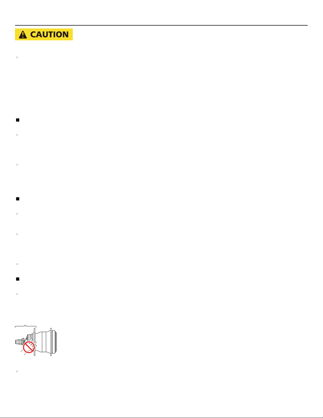
Assemble the wheel with 3x or 4x lacing, and do not spoke the wheel radially.
Otherwise, the spokes or the wheel may get damaged, or noise may occur when braking.
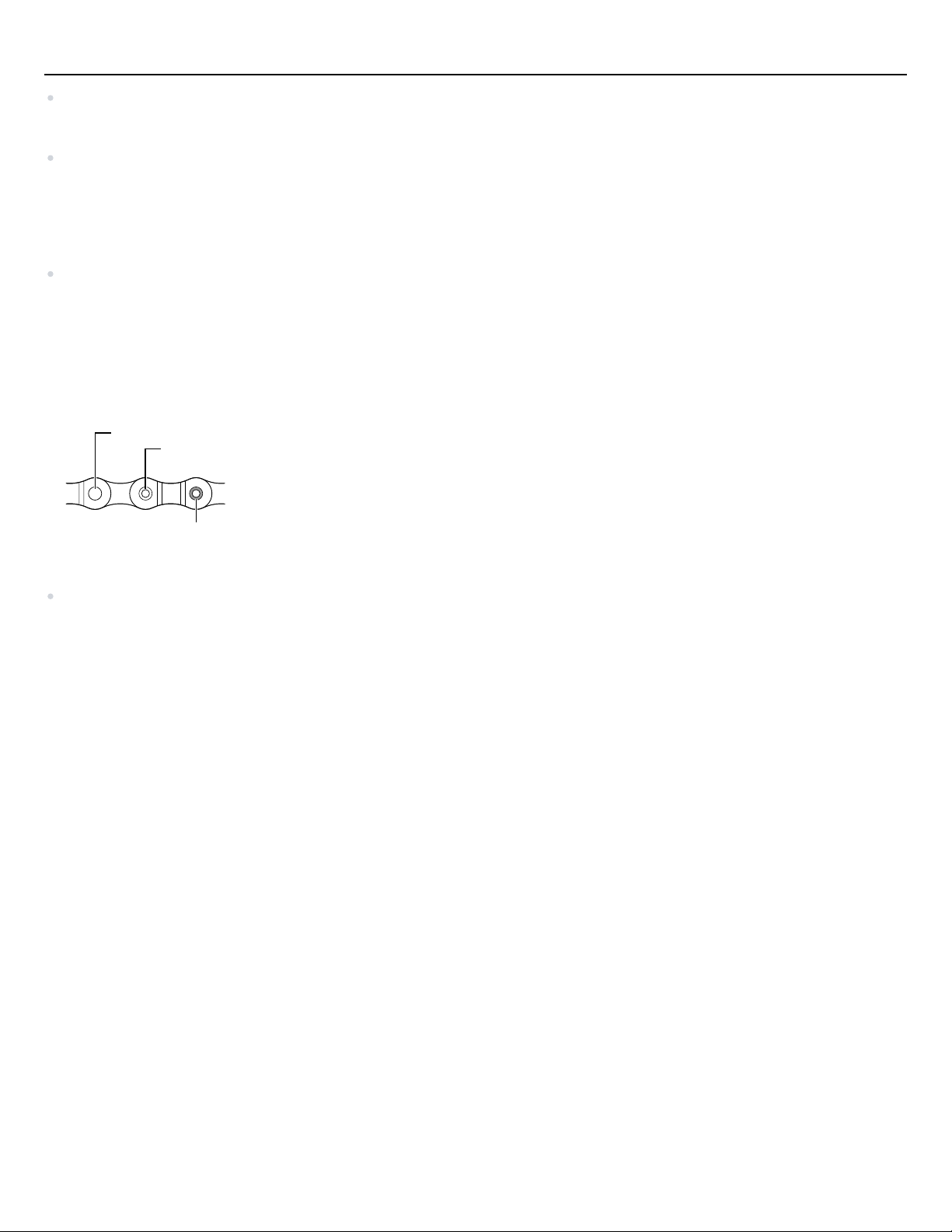
Never use alkali- or acid-based solvents such as rust cleaners. If those solvents are used the chain might break
and cause serious injury.
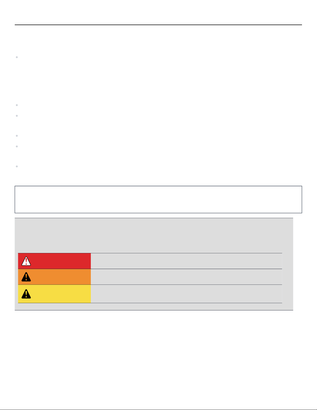
TO ENSURE SAFETY
6