Shimano Ultegra 6770 Series User manual

DM-0001A-001(English)
6770 Series
Dealer’s Manual
Please note: specifications are subject to change for improvement without notice. (English)
© Aug. 2011 by Shimano Inc. XBC

6770 Series
3
INTRODUCTION ··············································································································································· 4
TO ENSURE SAFETY ········································································································································· 5
ELECTRONIC GEAR SHIFTING SYSTEM··········································································································· 12
SYSTEM CONFIGURATION DETAILS ··············································································································· 14
SPECIFICATIONS············································································································································· 16
INSTALLATION ··············································································································································· 18
$
Installation of the dual control lever
$
Installation of the brake cables
$
Installation of the front derailleur···································································································· 19
$
Installation of the rear derailleur······································································································ 21
$
Installation of the chain
GEAR SHIFTING OPERATION·························································································································· 22
CONNECTION OF THE ELECTRIC WIRES ········································································································· 23
$
Names and example locations of each part
$
Front junction: Connection of junction (A) ······················································································ 24
$
Connection to the dual control lever
$
Installation of the battery mount ····································································································· 25
$
Installation and removal of the battery···························································································· 26
$
Rear junction: Connection of junction (B) External type
$
Rear junction: Connection of junction (B) Built-in type···································································· 29
$
Installation of the bottle cage adapter····························································································· 33
ADJUSTMENT ················································································································································ 34
$
Adjustment of the rear derailleur
$
Adjustment of the front derailleur ··································································································· 36
OTHER FUNCTIONS········································································································································ 38
$
Battery charge display function
$
Protection function
MAINTENANCE ·············································································································································· 39
$
Disassembly of the bracket unit and lever unit
$
Assembly of the switch unit ·············································································································· 40
$
Assembly of the bracket unit and lever unit····················································································· 41
$
Replacement of the pulley ················································································································ 42
HANDLING THE BATTERY ······························································································································ 43
$
Storing the battery
$
Battery life
$
Guide to charging time
$
Proper use of the battery ·················································································································· 44
BATTERY CHARGER········································································································································ 44
$
Charging the battery························································································································· 45
$
Troubleshooting
INTERCHANGEABILITY INFORMATION ·········································································································· 45
INDEX

4
5
This dealer’s manual is intended for use by people with specialist knowledge such as bicycle safety engineers and bicycle engineers.
If you are unsure about any of the information contained in this manual, never install the components yourself. Instead, contact the
place of purchase or a bicycle dealer.
This dealer’s manual can be viewed online on our website (http://techdocs.shimano.com/techdocs/index.jsp).
The following instructions must be observed at all times in order to prevent personal injury and physical damage to
equipment and surroundings.
The instructions are classified according to the degree of danger or damage which may occur if the product is used
incorrectly.
<Notes when reinstalling and replacing components>
When reinstalling or replacing components, be sure to disconnect the battery and wait for 10 seconds or more, and then reconnect
the battery. The units in the ULTEGRA Di2 6770 series (electronic gear shifting system) are designed to be recognized individually by
the system, and so if this step is not carried out, the components will not operate correctly.
Do not use anything other than the special charger to
charge the battery.
If any non-specified items are used, fire, overheating or
leakages may occur.
Do not heat the battery or throw it into fire. If this is not observed, fire or bursting may occur.
Do not leave the battery in places which may exceed 60°C
in temperature, such as places which are exposed to direct
sunlight inside vehicles on hot days or near stoves. If this is not observed, leakages, overheating or bursting
may cause fire, burns or other injury to occur.
Do not disassemble or modify the battery or apply solder
directly to the battery terminals.
Do not connect the (+) and (-) terminals with metallic
objects. Do not carry or store the battery together with
metallic objects such as necklaces or hairpins.
If this is not observed, short-circuits, overheating, burns or
other injury may occur.
If any liquid leaking from the battery gets into the eyes,
immediately wash the affected area with clean water
without rubbing the eyes, and then seek medical advice.
If this is not done, blindness may occur.
<SM-BTR1: Battery>
Do not get the charger wet or use it while it is wet, and do
not touch or hold it with wet hands.
If this is not observed, problems with operation or electric
shocks may occur.
Do not cover the charger with a cloth or similar while it is
in use.
If this is not observed, heat may build up and the case may
become deformed, or fire or overheating may occur.
Do not disassemble or modify the charger. If this is not observed, electric shocks or injury may occur.
Use the charger at the specified power supply voltage only.
If a power supply voltage other than that specified is used,
fire, explosions, smoke, overheating, electric shocks or
burns may occur.
Do not touch metallic parts of the charger or the AC
adapter if there is a lighting storm. If lightning strikes, electric shocks may occur.
<SM-BCR1: Battery Charger / SM-BCC1: Battery Charger Cord >
For safety, be sure to read this dealer’s manual thoroughly before use, and follow it for
correct use.
INTRODUCTION TO ENSURE SAFETY
Failure to follow the instructions will result in death or serious injury.
DANGER
Failure to follow the instructions could result in death or serious injury.
WARNING
Failure to follow the instructions could cause personal injury or physical damage to equipment and surroundings.
CAUTION
Be sure to observe the following in order to avoid burns or other injury from fluid leakages, overheating, fire or explosions.
DANGER

6
7
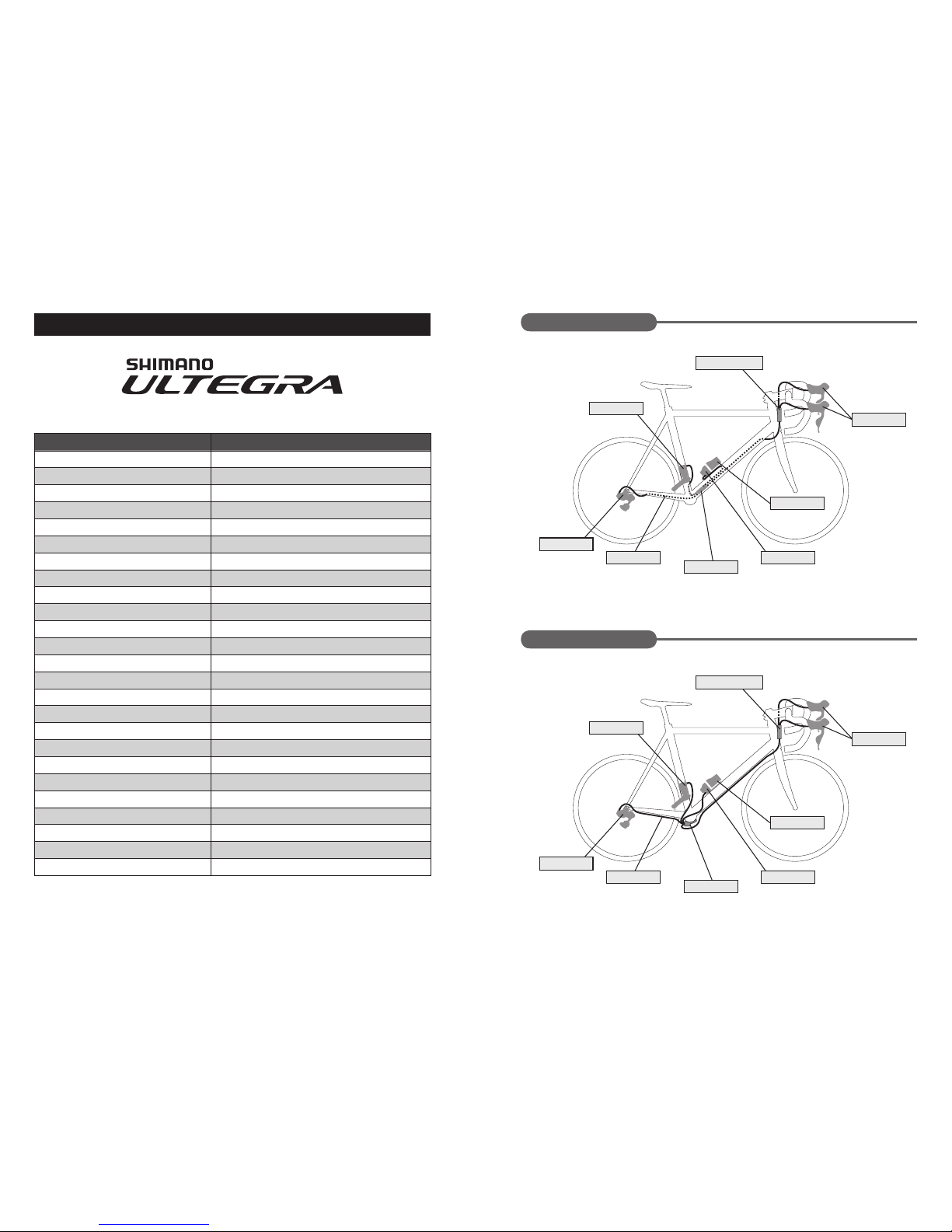
• Thisdealer’smanualisforusewiththeULTEGRA6770series(electronicgearshiftingsystem)only.Foranyinformationregarding
the ULTEGRA 6700 series which does not appear in this manual, refer to the Service Instructions included with each component.
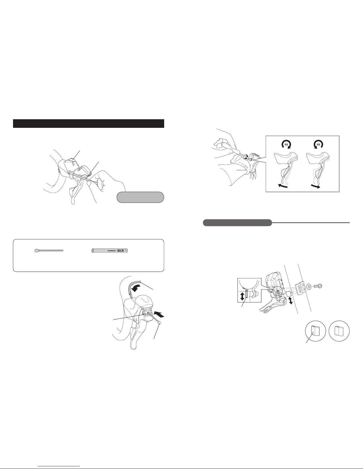
• Whentheshiftingswitchisoperated,themotorwhichdrivesthefrontderailleurwilloperatewithoutstoppingattheshifting
lever position. Always be sure to disconnect the battery before carrying out installation, otherwise your fingers may become
stuck.
• Wheninstallingcomponents,besuretofollowtheinstructionswhicharegiveninthedealer’smanual.Itisrecommendedthat
you use only genuine Shimano parts at this time. In addition, if parts such as bolts and nuts become loose or damaged, the bicycle
may suddenly fall over and serious injury may occur as a result.
• Wheninstallingcomponents,besuretofollowtheinstructionswhicharegiveninthedealer’smanual.Ifadjustmentsarenot
carried out correctly, problems may occur such as the chain coming off, and the bicycle may suddenly fall over and serious injury
may occur as a result.
• Afterreadingthisdealer’smanualthoroughly,keepitinasafeplaceforlaterreference.
If charging is not complete after 1.5 hours of charging time
has elapsed, stop the charging. If this is not observed, fire, bursting or overheating may
occur.
Do not place the battery into fresh water or sea water, and
do not allow the battery terminals to get wet.
The operating temperature ranges for the battery are given
below. Do not use the battery in temperatures outside
these ranges.
1. During discharge: –10°C - 50°C
2. During charging: 0°C - 45°C
If the battery is used or stored in temperatures which are
outside these ranges, fire, injury or problems with
operation may occur.
Do not use the battery if it has any noticeable scratching or
other external damage.
If this is not observed, bursting, overheating or problems
with operation may occur.
Do not subject the battery to strong shocks or throw it.
Do not use the battery if leakages, discoloration,
deformation or any other abnormalities occur.
If any leaked fluid gets on your skin or clothes, wash it off
immediately with clean water. The leaked fluid may damage the skin.
Do not use or place the battery at or near sources of fire.
If this is not observed, sparking, bursting, fire or electric
shocks may result.
Do not recharge the battery in places which have high
humidity or outdoors.
Do not insert or remove the plugs while they are wet. If the
insides of the plugs are wet, dry them thoroughly before
inserting them.
<SM-BTR1: Battery>
Be sure to hold the power cable by the power plug when
connecting and disconnecting the power plug from the
electrical outlet.
If you do not hold the power cable by the power plug, fire
or electric shocks may occur.
* If heat or acrid-smelling smoke is coming out from the
power plug.
* There may be a bad connection inside the power plug.
Do not overload the electrical outlet with appliances
beyond its rated capacity, and use only a 100 – 240 V AC
electrical outlet.
If the electrical outlet is overloaded by connecting too
many appliances using adapters, overheating resulting in
fire may occur.
Do not damage the power cord or power plug. (Do not
damage, process, forcibly bend, twist or pull them, bring
them near hot objects, place heavy objects on them or
bundle them tightly together.)
If they are used while damaged, fire, electric shocks or
short-circuits may occur.
Do not use the charger with commercially-available
electrical transformers designed for overseas use. If this is not observed, they may damage the charger.
Always be sure to insert the power plug as far as it will go. If this is not observed, fire may occur.
<SM-BCR1: Battery Charger / SM-BCC1: Battery Charger Cord>
<FC-6700: Front Chainwheel>
• Thetwoleftcrankarmmountingboltsshouldbetightenedalternatelyinstagesratherthaneachboltbeingfullytightenedallat
once. Use a torque wrench to check that the final tightening torques are within the range of 12 - 14 N·m. Furthermore, after
riding approximately 100 km (60 miles), use a torque wrench to re-check the tightening torques. It is also important to
periodically check the tightening torques. If the tightening torques are too weak or if the mounting bolts are not tightened
alternately in stages, the left crank arm may come off and the bicycle may fall over, and serious injury may occur as a result.
• Iftheinnercoverisnotcorrectlyinstalled,corrosionoftheaxlemayoccur,andthismaydamagetheaxleandthebicyclemayfall
over, and serious injury may occur as a result.
• Beforeridingthebicycle,checkthecrankarmsthoroughlytoseeiftheycontainanycracks.Ifthecrankarmsarecracked,they
may break and you may fall off the bicycle.
WARNING

Reinforced connecting pin
Link pin Link pin
8
9
<CN-6701: 10-speed Chain for Road Riding>
• Thefrequencyofmaintenancewillvarydependingonridingconditions.Periodicallycleanthechainusingan
appropriatechaincleaner.Donotusealkalineoracidiccleaningagentsforremovingrustunderanycircumstances.
Ifsuchcleaningagentsareused,theymaydamagethechainandseriousinjurymayresult.
• Inordertoobtaingoodgearshiftingperformance,applicablechainshaveaforwardsideandareverseside,andthe
sidesaremarkedsothatthechainswillfacethecorrectwaywheninstalled.Theproperdesignperformancewillbe
obtainedwhenthechainsareinstalledsothattheyfacethecorrectway.Ifthechainsareinstalledsothattheyface
theoppositeway,theymaycomeoffandthebicyclemayfalloverandseriousinjurymayoccurasaresult.
• Narrow-typechainsmustalwaysbeconnectedusingreinforcedconnectingpins.
• Ifthechainisconnectedbyusingconnectingpinsotherthanreinforcedconnectingpins,orbyusingreinforcedconnectingpins
or tools which are not suitable for the chain, the connecting force provided maybe insufficient, and the chain may break or fly
off.
• Afterconnectingthechain,besuretofeeltheconnectionwithyourfingerstocheckthatboth
ends of the connecting pin and the surfaces of the links are flush with each other. (The opposite
end of the pin which has been broken off should feel as though it is projecting very slightly.)
• Ifthelengthofthechainneedstobereadjustedforreasonssuchaschangestothesprocketconfiguration,cutthechainata
place which is not connected by means of a reinforced connecting pin. If you cut the chain at a place which has been connected
using a reinforced connecting pin, it will damage the chain.
• UseaTL-CN41chainwearindicator(Y12152000)orasimilartooltocheckifthechainhasbecomestretchedordamaged.Ifthe
chain has become stretched or damaged, it may break and the bicycle may fall over, so the chain should be replaced.
• Whenreadjustingthelengthofthechain,besuretoinsertthereinforcedconnectingpinfromthesamesideasthechaincutter
was inserted (the same direction as when the chain was cut).
• Becarefulnottoletthecuffsofyourclothesgetcaughtinthechainwhileriding,otherwiseyoumayfalloffthebicycle.
<SM-BCR1: Battery Charger / SM-BCC1: Battery Charger Cord>
• Disconnectthepowerplugfromtheelectricaloutletbeforecleaning.
<SM-BTR1: Lithium Ion Battery>
• Donotdisassembleorbreakthebattery.Ifthisisnotobserved,thereisthedangerthatfireorburnsmayresult.
• Donotheatthebatterytotemperatureswhichexceed60°C(140°F).Inaddition,donotputthebatteryintofire.Followthe
instructions provided by the battery’s manufacturer.
• Storethebatteryinasafeplaceawayfromthereachofinfantsandpets.
• Besuretorotatethefrontchainwheelwhencarryingoutanyleveroperationswhicharerelatedtogearshifting.
• Besuretoattachdummyplugstoanyunusedterminals.
• Becarefulnottoletwatergetintotheterminals.
• Theunitsaredesignedtobefullywaterprooftowithstandwetweatherridingconditions.However,donotdeliberatelyplace
them into water.
• AlwaysbesuretousetheTL-EW02specialtooltoremovetheelectricwires.
• Ifgearshiftingoperationscannotbecarriedoutsmoothly,cleanthefrontandrearderailleursandlubricateanymovingparts.
• Periodicallywashthechainringsandsprocketswithneutraldetergentandthenlubricatethem.Inaddition,cleaningthechain
with neutral detergent and then lubricating it will also help to extend the life of the chainrings and sprockets and the chain.
• Ifthechainkeepscomingoffthesprocketsduringuse,replacethesprocketsandthechain.
• Donotusethinnerorothersolventstocleananyofthecomponents.Suchsubstancesmaydamagethesurfaces.
• Donotcleanthebicycleinahigh-pressurecarwash.Ifwatergetsintoanyofthecomponents,operatingproblemsorrusting
may result.
• Donotdisassemble,otherwiseoperatingproblemswillresult.
• Themotorsofthefrontderailleurandtherearderailleurcannotberepaired.
• Handlethecomponentscarefully,andavoidsubjectingthemtoanystrongshocks.
• Contacttheplaceofpurchaseforupdatesofthecomponentsoftware.Themostup-to-dateinformationisavailableonthe
Shimano website.
• ContactShimanoforinformationregardingtheshipmentofthebatterychargertoSouthKoreaandMalaysia.
• Naturalwearanddeteriorationwhichoccursasaresultofnormaluseisnotcoveredbywarranty.
CAUTION
NOTE
Chain Reinforced connecting pin Tool
CN-7901 / 6701 / 5701 /4601
10-speed compatible super-narrow chain
Grooved (3) TL-CN32/33
TL-CN23
TL-CN27
Grooved (2)
Forward (outer side)
The side with the marks shown in the illustration is the forward side (outer side).
Reverse (inner side)
<SM-BCR1: Battery Charger / SM-BCC1: Battery Charger Cord>
• Ifnotusingthebatteryforlongperiods,removeitandstoreitawayinasafeplace.
• Usedbatteriesshouldbedisposedofinaccordancewithlocalwasteregulations.Alternatively,asktheplaceofpurchaseora
bicycle dealer for disposal.
• Thisapplianceisnotintendedforusebypersons(includingchildren)withreducedphysical,sensoryormentalcapabilities,orlack
of experience and knowledge, unless they have been given supervision or instruction concerning use of the appliance by a person
responsible for their safety.
• Donotletchildrenplayneartheseitems.
Information on disposal in countries other than the European Union
This symbol is only applicable within the EU.
Used electrical items (battery chargers and battery charger cords) should be disposed
of in accordance with local laws and regulations, or ask the place of purchase or a
bicycle dealer for disposal.

Inner link
Inner link
Outer link
Outer link
Connecting pin
Connecting pin
A
B
10
11
<SM-BTR1: Battery>
• Thebatteryisunchargedatthetimeofpurchase.Beforeriding,besuretochargethebatteryuntilitisfullycharged.
• Whenstoringthebatteryaway,removethebatteryfromthebicycleandinstalltheterminalcoverfirst.
• Ifthebatteryisstoredawaywhilethebatterychargeis50%orhigher(theindicatorisilluminatedgreen),thebatterywilllast
longer.
It is recommended that you check the condition of the battery about once every half a year.
• Ifthebatteryisstoredincoldlocations,theperformanceofthebatterymaydropandthelengthoftimethatitcanbeusedmay
become shortened.
• Thebatteryisaconsumableitem.Thebatterywillgraduallyloseitscapacityforchargingafterrepeateduseandaftertimehas
passed. If the length of time that the battery can be used becomes extremely short, it has probably reached the end of its life,
and so you will need to purchase a new battery.
• Thelifeofthebatterywillvarydependingonfactorssuchasthestoragemethod,theusageconditions,thesurrounding
environment and the characteristics of the individual battery pack.
• Thechargingtimeisapproximately1.5hours.(Notethattheactualtimewillvarydependingontheamountofchargeremaining
in the battery.)
• Ifthebatteryfeelsdifficulttoinsertorremove,applyspecifiedgrease(DURA-ACEgrease)tothepartthattouchestheO-ringat
the side.
• FortheDURA-ACE(7970),thebicyclecanberiddenforapproximately1000kmonafullcharge.FortheULTEGRA(6770),the
ridingdistancewillbeshorter.(Approximately30%lessaccordingtotestscarriedoutbyShimano.)
• Chargingcanbecarriedoutatanytimeregardlessoftheamountofchargeremaining.Alwaysbesuretousethespecialbattery
charger to charge the battery until it is fully recharged.
• Ifthebatteryhasbecomefullyspent,chargeitassoonaspossible.Ifyouleavethebatterywithoutchargingit,itwillcausethe
battery to deteriorate.
• Ifyouwillnotberidingthebicycleforalongperiod,removethebatteryfromthebicycleandrechargeitperiodically.In
addition, take care not to let the battery become fully spent.
<EW-SD50/EW-SD50-I: Electric Wires / SM-EWC2: Electric Wire Covers>
• Securetheelectricwireswithcabletiessothattheydonotinterferewiththechainrings,sprocketsandtires.
• Thestrengthoftheadhesiveisfairlyweak,topreventthepaintontheframefrombeingpeeledoffatthesametimewhen
removing the electric wire cover for reasons such as replacing the electric wires. If the electric wire cover is peeled off, replace it
with a new one.
When removing the electric wire cover, do not peel it off too vigorously. If this is not observed, the paint on the frame will peel
off too.
• Donotremovethewireholderswhichareattachedtothebuilt-intypeelectricwires(EW-SD50-I).Thewireholderspreventthe
electric wires from moving inside the frame.
<ST-6770: Dual Control Lever>
• Dummyplugsareinstalledatthetimeofshipmentfromthefactory.Donotremovethemexceptwhennecessary.
• Besuretorotatethefrontchainwheelwhencarryingoutanyleveroperationswhicharerelatedtogearshifting.
• Whenroutingtheelectricwires,takecaretoensurethattheydonotinterferewiththebrakelevers.
<RD-6770: Rear Derailleur>
• Alwaysbesuretoadjustthetopadjustmentboltandthelowadjustmentboltaccordingtotheinstructionsgiveninthe
adjustment section. If these bolts are not adjusted, the chain may become clamped between the spokes and the large sprocket
and the wheel may lock, or the chain may slip onto the small sprocket.
• Iftheamountofloosenessinthelinksissogreatthatadjustmentisnotpossible,youshouldreplacethederailleur.
• Periodicallycleanthederailleurandlubricateallmovingpartsandpulleys.
• Ifgearshiftingadjustmentscannotbecarriedout,checkthedegreeofparallelofthereardropouts.
• Ifthereisalargeamountofplayinthepulleyswhichcausesworryingnoisewhileriding,replacethepulleys.
• Thetensionpulleyhasanarrowonittoindicatethedirectionofrotation.Installthetensionpulleysothatthearrowispointing
clockwise when looking at the pulley from the outside.
• AsillustratedinFig.A,westronglyrecommendtosettheconnectingpinintheholeoftheouterlinkonthefrontsideinthe
direction of travel. The chain’s level of strength is enhanced compared to the method in Fig. B.
<CN-6701: 10-speed Chain for Road Riding>
Chain’s
directionof
travel
Information on disposal in countries other than the European Union
This symbol is only applicable within the EU.
Used batteries should be disposed of in accordance with local laws and regulations, or
ask the place of purchase or a bicycle dealer for disposal.
• Placethechainintothechaincuttingtoolasshownintheillustration.Ifthechainissetincorrectlyintothechaincuttingtool,it
will break the positioning plate.

SM-EW67-A-E
FD-6770
ST-6770
SM-BTR1
SM-BMR1
RD-6770
EW-SD50-I
SM-JC41
SM-EW67-A-E
FD-6770
ST-6770
SM-BTR1
SM-BMR1
RD-6770
EW-SD50
SM-JC40
12
13
In order to obtain the optimum performance, it is recommended that you use the following combination of components.
ELECTRONIC GEAR SHIFTING SYSTEM
Series ULTEGRA 6770
Dual control lever ST-6770*
Tool TL-EW02
Front derailleur FD-6770*
Band adapter SM-AD67
Rear derailleur RD-6770*
Chain CN-6701
Front junction: Junction (A) SM-EW67-A-E*
Electric wires EW-SD50* / EW-SD50-I*
Electric wire cover SM-EWC2*
Grommets SM-GM01* / GM02*
Lithium ion battery SM-BTR1*
Battery charger SM-BCR1*
Battery charger (SM-BCR1) cord SM-BCC1*
Battery mount SM-BMR1*
Bottle cage adapter SM-BA01
Rear junction: Junction (B) SM-JC41* (built-in type) / SM-JC40* (external type)
E-tube Project (system checker) SM-PCE1
Front chainwheel (bottom bracket) FC-6700 / FC-6750 (SM-BB6700)
Front hub HB-6700
Freehub FH-6700
Cassette sprocket CS-6700
Caliper brakes BR-6700
Cantilever brakes BR-CX70
Wheels WH-6700
Pedals PD-6700-C / PD-6700
* These components are part of the ULTEGRA 6770 series (electronic gear shifting system).
Built-in type (SM-JC41)
External type (SM-JC40)

(ST-6770)
(SM-AD67L)
(EW-SD50)
(SM-AD67M)
(TL-EW02)
(EW-SD50-I)
(SM-BMR1-I)
(SM-BMR1-L)
(SM-BMR1-S)
(SM-JC41) (SM-JC40)
14
15
$
Dualcontrollever(ST-6770)/
Electricwiretool(TL-EW02)
$
Frontderailleur(FD-6770)
$
Bandadapter(SM-AD67)
$
Rearderailleur(RD-6770)
$
Frontjunction:Junction(A)
(SM-EW67-A-E)
$
Electricwires
(EW-SD50/EW-SD50-I)
SYSTEM CONFIGURATION DETAILS
$
Electricwirecover(SM-EWC2)
$
Batterymount(SM-BMR1)
$
Bottlecageadapter
(SM-BA01)
$
E-tubeProject:
Systemchecker(SM-PCE1)
$
Rearjunction:Junction(B)
Built-intype(SM-JC41)/
Externaltype(SM-JC40)
$
Framegrommets
(SM-GM01/SM-GM02)
$
Lithiumionbattery
(SM-BTR1)
Accessories
• Terminalcover
Accessories
• Cabletie(x1)
• LowheadM4bolt(x1)
• Spacer(x3)
Accessories
• Cabletie(x1)
• LowheadM4bolt(x1)
Accessories
• PC-linkcable(x2)2m
• USBcable(x1)50cm
$
Batterycharger(SM-BCR1)
$
Batterychargercord
(SM-BCC1)
Accessories
• M4bolt(x2)

16
17
$
Front derailleur
$
Batterycharger
$
Batterychargercord
(Refer to page 46)
SPECIFICATIONS
Type Brazed-on type Band type
Model number FD-6770-F FD-6770-L FD-6770-M FD-6770-S
Band adapter
(installation band diameter) –SM-AD67L
(34.9 mm)
SM-AD67M
(31.8 mm)
SM-AD67MS
(28.6 mm)
Number of larger chainring teeth 50 - 56 T
Difference in number of larger and
smaller chainring teeth 16T or less
Chainstay angle (a)61° - 66°
Chain line 44.45 mm
$
Battery
Battery unit Lithium ion
Nominal capacity 530 mAh
Weight Standard 71 g
Operating temperature range During discharge: –10°C - 50°C
During charging: 0°C - 45°C
Storage temperature range –20 - 60 °C
Nominal voltage 7.4 V
$
Rear derailleur
Type SS
Total capacity 33 T
Maximum no. of largest sprocket teeth 28 T
Minimum no. of largest sprocket teeth 23 T
Maximum no. of smallest sprocket teeth 12 T
Minimum no. of smallest sprocket teeth 11 T
Difference in number of teeth from front 16T or less
Input 100-240VAC,50/60Hz
Output 8.4 V DC, 0.55 A
Dimensions Approx.100mm(W)x30mm(H)x72mm(D)
Weight Approx. 110 g
Operating temperature 0 - 45 °C
Storage temperature –20 - 60 °C

Bracket cover
5mm Allen key
Support bolt
Outer casing
Inner cable drum
Cable hook
Duct tape
18
19
$
Installationofthedualcontrollever
Open up the bracket cover from the front, and then use a 5 mm Allen key to tighten the mounting nut
in order to secure the lever unit.
$
Installationofthefrontderailleur
1. Install the front derailleur to the frame.
$
Installationofthebrakecables
When installing the components to carbon frame/handle bar surfaces, verify with the manufacturer of the carbon frame/parts for
their recommendation on tightening torque in order to prevent over tightening that can cause damage to the carbon material and/
or under tightening that can cause lack of fixing strength for the components.
The lever stroke can be smoothly adjusted using the bolt on the top of the bracket unit. Check the lever operation while adjusting.
If installing the front derailleur to a brazed-on type frame, a protector must be attached to the seat tube. Always be sure to
install the protector in order to prevent damage to the frame from the pressure applied by the support bolt of the front
derailleur.
Installation of the protector
Check the position where the support bolt directly touches the frame when the support bolt of the front derailleur is being
adjusted, and attach the protector in that position. In addition, avoid positioning the duct tape that attaches the protector to
the seat tube in the location where the support bolt directly touches the frame.
* Protectors with a curved adhesion surface and a flat adhesion surface exist as
shown in the illustration, so use whichever type matches the shape of the frame.
Use cables which are long enough so that they still have some slack even when the handlebars are turned as far as they
will go to the left and to the right.
1. Gently pull the brake lever.
2. Pass the inner cable through from directly in front, set the inner cable drum
into the cable hook, and then install the outer casing from the opposite side.
Cablesused
INSTALLATION
Inner cable ... 1.6 mm dia. SLR outer casing ... 5 mm dia.
Tightening torque:
6 - 8 N·m {52 - 69 in. lbs.}
When installing a brazed-on type

Support bolt
Band adapter
B-tension adjustment bolt
5mm Allen key
Pulley cage
Largest sprocket
Smallest sprocket
Larger chainring
Larger chainring
Chain + 2 links
Tension pulley
Guide pulley
Chain
Dropout tab
Clearance1-3mm
0.5 - 1.0 mm
90º
Chain guide outer plate
Chain guide
Front chainwheel
(large chainring)
20
21
* If using the band adapter (SM-AD67), a support bolt will be necessary. A protector and a mounting washer will not be needed.
Use the SM-AD67 in combination with the FD-6770. The SM-AD11/15 cannot be installed.
When installing the components to carbon frame/handle bar surfaces, verify with the manufacturer of the carbon frame/parts
for their recommendation on tightening torque in order to prevent over tightening that can cause damage to the carbon
material and/or under tightening that can cause lack of fixing strength for the components.
When installing the rear derailleur, make sure that the B-tension adjustment bolt does not
touch the dropout tab and cause it to bend.
2. Adjust so that there is a clearance of 1 - 3 mm between the chain guide
outer plate and the large chainring.
4. Use a 2 mm Allen key to turn the support bolt in order to adjust the
position of the front derailleur so that the flat part of the chain guide
outer plate is directly above and parallel to the large chainring.
3. Use a 5 mm Allen key to secure the chain guide outer plate so that the
flat part of the plate is directly above the large chainring and so that
the rear edge of the chain guide is within 0.5 – 1.0 mm from the front
edge of the chain guide.
When installing a band type
Chain length
$
Installationoftherearderailleur
$
Installationofthechain
Forward (outer side)
Note:
* This 10-speed chain for road riding has a differently-shaped forward side and reverse side in order to improve high gear
shifting performance.
* If the largest sprocket is 28T or more
Add 2 links while the chain is on the larger chainring and the
largest sprocket.
Reverse (inner side)
The side with the marks shown in the illustration is the forward side (outer side).
Tightening torque:
5 - 7 N·m {43 - 60 in. lbs.}
Tightening torque:
5 - 7 N·m {43 - 60 in. lbs.}
Bracket tightening torque:
8 - 10 N·m {70 - 86 in. lbs.}

Shifting switch (X)
Shifting switch (X)
Shiftingswitch(Y)
Shiftingswitch(Y)
SM-EW67-A-E
SM-EW67-A-E
EW-SD50
EW-SD50-I
SM-JC40
SM-JC41
22
23
$
Dualcontrollever(ST-6770)
$
Namesandexamplelocationsofeachpart
<Shifting switch (X)>
The chain moves from a smaller sprocket to a larger sprocket
each time the switch is operated.
<Shifting switch (X)>
The chain moves from the smaller chainring to the larger
chainring.
<Shifting switch (Y)>
The chain moves from a larger sprocket to a smaller sprocket
each time the switch is operated.
<Shifting switch (Y)>
The chain moves from the larger chainring to the smaller
chainring.
GEARSHIFTINGOPERATION CONNECTION OF THE ELECTRIC WIRES
Operating the rear shifting switches (initial settings) Built-in type (SM-JC41)
External type (SM-JC40)
Operating the front shifting switches (initial settings)
• Ifthechainfallsoffontheinside,keeppressingshiftingswitch(X)for1secondormoretomovethefrontderailleurto
the outermost position, and then keep it pressed for 10 seconds in order to reset the chain.
• ThereisafunctionusingtheSM-PCE1forchangingbetweenshiftupandshiftdownoperationsforshiftingswitches(X)
and(Y)andtherearshiftingswitchandfrontshiftingswitch.
* For details on changing the shifting switches, refer to the help screens for E-tube Project (PC application).

108mm
Cable tie
2mm Allen key
Battery mount fixing bolt
(M4 x 15mm)
(Sample connection diagram for ST-6770 and SM-EW67-A-E)
24
25
$
Frontjunction:Connectionofjunction(A)
1. Use the TL-EW02 special tool to connect to the ST-6770. Set so that the projection on the
connector is aligned with the groove on the narrow end.
1. Set the battery mount into position. Use the bottle cage fixing bolt to provisionally install the battery mount to the bottom of
the bottle cage.
Use the bolts which are included with the bottle cage to secure
the SM-BMR1-L (long type).
Refer to the Service Instructions for the bottle cage for details
on the tightening torques.
3. Tighten the bolt of the bottle cage to secure the battery
mount. For the SM-BMR1-L (long type), use the accessory
cable tie to secure the battery mount to the frame.
2. Leave a space of 108 mm or more at the end of the battery
mount. Check that the battery can be inserted and removed
while the bottle cage is installed.
Use the included M4 bolts to secure the SM-BMR1-S
(short type).
* The remaining terminal can be used for an additional
satellite switch or the SM-PCE1.
2. Open up the bracket cover and lift up the connector cover.
Use the TL-EW02 to connect the connector of the electric wire to the
terminal on the lever side. Be sure to push them together until they
connect with a click. Either the top or bottom terminal can be used.
3. Use the accessory cable ties to secure junction (A) to the outer
casing of the brake cable.
$
ConnectiontotheDualcontrollever
$
Installationofthebatterymount
When routing the SM-EW67-A-E, allow enough looseness in the cable
so that the ST-6770 installation position can be adjusted and so that
the handlebars can be turned fully to the left and right. When
routing the electric wires, they can be wrapped around the
handlebars when wrapping the handlebar tape.
Tightening torque:
1.2 - 1.5 N·m {10.4 - 13 in. lbs.}
Tightening torque:
1.2 - 1.5 N·m {10.4 - 13 in. lbs.}
Tightening torque:
1.2 - 1.5 N·m {10.4 - 13 in. lbs.}
* If there is a mounting boss on the frame, the battery
mount can be secured to the frame with a bolt.

Clearance
Junction (A)
Junction (B)
At front derailleur At rear derailleur
At battery mount
26
27
1. Open the clamp, and then install the battery so that it follows the groove in the battery mount. Close the clamp until it clicks
into place.
2. Open the clamp, pull out the battery slightly, and then press the button to fully remove the battery.
2. Connect the electric wires to the front derailleur, the rear derailleur and the battery mount.
3. Provisionally secure the electric wire along the frame with tape, and
then connect it to junction (B).
* When routing the electric wire to the rear derailleur, be sure to
install it to the bottom of the chainstay to avoid any interference
between the cable and the chain.
* Wind any excess length of electric wire inside junction (B) to adjust
the length.
$
Installationandremovalofthebattery
$
Rearjunction:Connectionofjunction(B)
Example of adjusting junction (B) length
1. Connect the electric wires to junction (A) and junction (B). Be sure to push them together until they
connect with a click.
External type (SM-JC40)

Junction (B) fixing bolt
(10.5mm or 15mm)
(3mm Allen key)
Shifting switch (X)
ST-6770
FD-6770 RD-6770
SM-JC40 SM-JC41
Wire holder
Electric wire for front derailleur
Electric wire for junction (A)
Electric wire for rear derailleur
Bottom bracket shell
Electric wire for battery mount
28
29
4. Once the electric wires have been routed, secure junction (B) underneath the bottom bracket shell.
5. Next, install the electric wire cover to the frame. In order to make sure that the
electric wire cover is securely installed, clean the frame with alcohol or some other
cleaning agent to remove any grease or other substances before installing the cover.
Place the electric wire cover over the electric wires, and then attach it to the frame.
Checking connections
After connecting the electric wires to all of the components, install the battery and check the
operation.
Operate the shifting switches and check that the front derailleur and rear derailleur both operate.
Note:
* If not installing the chain at this point, be sure to operate shifting switch (X) for the left lever once
or more to set the front derailleur to the larger chainring position when installing the chain. After
this, be sure to remove the battery.
Disconnection of the electric wires
Use the wide end of the TL-EW02 special tool to disconnect the electric
wires. If you pull too firmly on the connectors, problems with operation
may occur. Insert the special tool so that the flat side is facing toward
the derailleur, and then tilt it so as to pull out the connector of the
electric wire.
* Run any excess length of electric wire along the handlebar, and use cable ties or similar to secure the electric wire to the
handlebar.
When disconnecting the electric wire from a lever, face the flat side toward the lever. When disconnecting the connector of
junction (A) or junction (B), insert the special tool so that the flat side is facing toward junction.
$
Rearjunction:Connectionofjunction(B)
1. First pass the electric wires for junction (A), the battery mount,
the front derailleur and the rear derailleur through the holes in
the frame into the bottom bracket shell.
* The electric wires have a correct way of being inserted. Make
sure that you insert them from the direction shown in the
illustration.
Built-in type (SM-JC41)
Tightening torque:
1.5 - 2 N·m {13 - 18 in. lbs.}

At front derailleur
At junction (A)
At battery mount
At rear derailleur
For front derailleur
For rear derailleur
Adapter Adapter
Adapter
Inner cover
For battery mount
Junction (B)
For junction (A)
Inner cover
30
31
2. Connect each electric wire to junction (B). Be sure to push them together
until they connect with a click. 1 2
3
3. Connect the electric wires to junction (A), the front derailleur, the rear derailleur and the battery mount.
Routing junction (B) and the electric wires inside the frame
1. Pass the electric wires for the front derailleur and the rear derailleur through the seat tube and chainstay respectively.
2. Pass the electric wires for junction (A) and the battery mount and junction (B) through the down tube. Check that the screws of
the bottom bracket shell do not damage any of the components at this time.
3. Set the electric wires so that only the electric wires for the front derailleur and the rear derailleur are visible inside the bottom
bracket shell, and if any extra parts such as wire holders are protruding, push them back inside the frame.
Assembly of the bottom bracket shell
1. When installing the inner cover to the bottom bracket shell, make sure that the electric wires for the front derailleur and the
rear derailleur pass over the top of the inner cover.
2. Install the inner cover to the bottom bracket adapter.
Note:
* If using a frame which does not have enough space between the inside of the
bottom bracket shell and the inner cover to route the electric wires use an inner
cover which is sold separately.

3mm Allen key
10mm
15mm
15mm
10mm
Spacers
Tightening torque:
3 N·m {26 in. lbs.}
Cable tie
Spacers
Closed Open
At rear derailleur
At junction (A)
At front derailleur
2mm Allen key
Battery mount fixing bolt
(M4 x 15mm)
32
33
Installation of the battery mount
1. Set the electric wire for the battery mount into the groove in the electric wire cover for the battery mount.
2. Place the accessory spacers in between the battery mount and the frame and then secure them by tightening the bolts.
* If installing the bottle cage, it is easier to install it at this stage.
* Refer to the Service Instructions for the bottle cage for details on the tightening torques.
3. Use the accessory cable tie to secure the battery mount to the frame.
1
2
3
* If there is a mounting boss on the frame, the
battery mount can be secured to the frame with
a bolt.
Installation of the grommets
Install grommets in appropriate positions for the electric wires by inserting the bottoms into the holes in the frame and then
pushing the tops to fit them into place.
If the bottle cage which is installed to the seat tube
interferes with the battery, move the position of the bottle
cage upward. The installation position for the bottle cage
can be moved upward by a minimum of 32 mm and a
maximum of 50 mm from the original installation position.
* If it interferes with the mounting boss for the front
derailleur, use the accessory spacer.
* Refer to the Service Instructions for the bottle cage for
details on the tightening torques.
$
Installationofthebottlecageadapter
Tightening torque:
1.2 - 1.5 N·m {10.4 - 13 in. lbs.}

Junction (A)
Rear derailleur
adjustment button
Illuminates (red)
Rear derailleur
adjustment button
2mm Allen key
2mm Allen key
Low adjustment bolt
Top adjustment bolt
Turned off
4 steps
4 times
34
35
$
Adjustmentoftherearderailleur
ADJUSTMENT
1. Install the battery.
2. Shift the rear derailleur to the 5th sprocket position. Press the button at the junction (A) of the SM-EW67-A-E until the red LED
illuminates in order to switch to rear derailleur adjustment mode. Note that if you keep pressing the button after the red LED
has illuminated, protection recovery operation will begin.
* For details on protection function, refer to ‘Protection function’ on page 38.
3. If shifting switch (X) is pressed once while the initial setting condition is active, the guide pulley will move one step toward the
inside.
Ifshiftingswitch(Y)ispressedonce,theguidepulleywillmoveonesteptowardtheoutside.
The guide pulley can move 15 steps inward and 15 steps outward from the initial position, for a total of 31 positions.
When adjusting, the guide pulley will overrun slightly and then move back in an exaggerated movement so that you can check
the adjustment direction. When checking the positions of the guide pulley and the sprocket, check at the position where the
guide pulley finally stops.
4. While turning the front chainwheel, operate shifting switch
(X) to move the guide pulley toward the inside until the chain
touches the 4th sprocket and makes a slight noise.
5. Next,operateshiftingswitch(Y)4timestomovetheguide
pulley toward the outside by 4 steps to the target position.
6. Press the button at junction (A) until the red LED turns off in order to switch from rear
derailleur adjustment mode to gear shifting mode. Shift to each gear and check that
no noise is generated at any gear position. If fine adjustment is needed, switch back
to adjustment mode and readjust the rear derailleur.
7. Next, carry out the adjustments for the low adjustment bolt and top adjustment bolt.
<Low adjustment>
Shift the rear derailleur to the largest sprocket, and then tighten the low adjustment
bolt until it touches against the stopper.
If it is tightened too much, the motor will detect a problem and gear shifting operation
will not be carried out correctly.
<Top adjustment>
Shift the rear derailleur to the smallest sprocket, and then tighten the
top adjustment bolt until it touches the stopper at the position where
the rear derailleur finally stopped. From this position, turn the top
adjustment bolt counterclockwise one turn so that an over-stroke
allowance can always be maintained.
Symptom
• Doesnotshifttolowgear.
• Noisedoesnotstop.
• Batterychargedisappearsquickly.
(load is being placed on the motor.)

0 - 0.5 mm
0.5 - 1.0 mm
Guide pulley
Low adjustment bolt
Support bolt
Top adjustment bolt
B-tension
adjustment bolt
Smallest sprocket
Largest sprocket
36
37
By shifting from a large sprocket to a smaller sprocket, the rear derailleur will move
toward the outside by the over-stroke allowance and then move back.
8. Adjust the B-tension adjustment bolt.
Set the chain onto the smaller chainring and the largest
sprocket, and then turn the crank arms backward. Turn the
B-tension adjustment bolt to adjust so that the guide pulley
moves close to the sprocket without obstructing the chain. Next,
set the chain onto the smallest sprocket and check in the same
way that the guide pulley does not obstruct the chain.
$
Adjustmentofthefrontderailleur
Note:
* The low adjustment bolt, the top adjustment bolt and the support bolt are close to each other. Make sure that you are using the
correct bolt for adjustment.
<Low adjustment>
Set the chain onto the smaller chainring and the largest sprocket. Use a 2 mm
Allen key to turn the low adjustment bolt to adjust so that there is a clearance of
0 - 0.5 mm between the chain and the chain guide inner plate.
<Top adjustment>
Next, set the chain onto the larger chainring and the smallest sprocket. Use a 2
mm Allen key to turn the top adjustment bolt to adjust so that there is a
clearance of 0.5 - 1.0 mm between the chain and the chain guide outer plate.
Move the front derailleur and the rear derailleur to all gear positions, and check
that the chain guide does not touch the chain.

Return spring
Lever stud
Junction (A)
Illuminates (red)
Special E-ring
removal tool
Y6RT68000
Rear derailleur adjustment
button
Button hold down Illuminates (red) Flashes (red) Protection clear operation
Protection cleared
Approx. 5 seconds in total
(A)
(B)
38
39
$
Disassemblyofthebracketunitandleverunit
1. Use the special tool which is sold separately to remove the E-ring.
Align part B of the special tool with the removal direction of the E-ring. Next, set part A onto the E-ring and remove the E-ring.
2. Insert an Allen key or a similar tool into the hole in the lever stud, and then
tap it with a plastic mallet to push out the lever stud.
3. Remove the return spring.
MAINTENANCE
Note:
* The E-ring may fly off suddenly during removal, so check that there are no people or objects nearby while
removing the E-ring.
* The illustrations show the right-side lever.
$
Protectionfunction
* Rotate the front chainwheel while restoring operation after the protection function has been activated.
If the bicycle receives a strong impact, the protection function operates and the connection between the motor and the link is
momentarily severed so that the rear derailleur will no longer operate. This is done in order to protect the system at times such as if
the bicycle falls over. If this happens, press the rear derailleur adjustment button on junction (A) of the SM-EW67-A-E for 5 seconds
or more. This will restore the connection between the motor and the link and clear the protection function for the rear derailleur.
If the connection is not restored, push/pull the cage sideways or move it forward and backward by hand. Operate the shifting
switches to check that the connection has been restored.
WhentheredLEDonjunction(A)isilluminated,therearderailleurcannotshiftgears.Keeppressingtherearderailleuradjustment
button until the red LED turns off.
$
Batterychargedisplayfunction
Pressandholdeithershiftingswitchfor0.5secondsormore.Youcanchecktheamountofbatterychargeremainingusingthe
battery indicator on junction (A).
* When the battery charge is low, first the front derailleur will stop operating, and then the rear derailleur will stop operating.
When the battery charge has been fully spent, the derailleurs will be fixed at the last gear shifting position. If the battery
indicator is illuminated red, it is recommended that you recharge the battery as soon as possible.
OTHER FUNCTIONS
Illuminates green (for 2 seconds)
Flashes green (5 times)
Illuminates red (for 2 seconds)
Flashes red (5 times)
100 %
50 %
25 %
0 %
Batteryindicator
Table of contents
Other Shimano Bicycle manuals