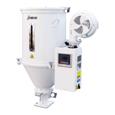
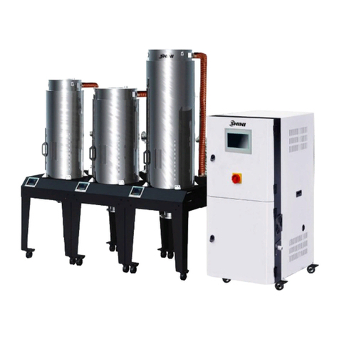
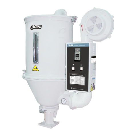
Shini SCD-80Ux2/100H User manual

SCD
"One-to-Two" CompactDryer
Date:Aug. 2018
Version:Ver.A(English)


3(62)
Contents
1. General Description..................................................................................... 9
1.1 CodingPrinciple.................................................................................... 10
1.2 Features................................................................................................ 10
1.3 TechnicalSpecifications........................................................................ 12
1.4 SafetyRegulations................................................................................ 13
1.4.1 SafetyRegulationsforthe Blowers.............................................. 13
1.4.2 SafetySignsand Labels.............................................................. 14
1.4.3 Signsand Labels......................................................................... 14
1.4.4 Transportation andStorageoftheMachine................................. 15
1.5 ExemptionClause................................................................................. 16
2. StructureCharacteristics and WorkingPrinciple.................................... 17
2.1 WorkingPrinciple.................................................................................. 17
2.2 RelativeHumidityand Dew-point.......................................................... 18
2.3 Options.................................................................................................. 18
2.3.1 Installation forDewpoint Monitor,Add"D"at the endof themodel
code.18
2.3.2 OtherOptions.............................................................................. 21
3. Installation Testing..................................................................................... 22
3.1 Machine Allocation ................................................................................ 22
3.2 Duct andFeed Tube Connection.......................................................... 23
3.3 WaterConnection ................................................................................. 23
3.4 Air SupplyConnection........................................................................... 24
3.5 ElectricalConnections........................................................................... 24
4. Application and Operation......................................................................... 25
4.1 DehumidifyingSystemOperation.......................................................... 25
4.2 TemperatureSetup............................................................................... 25
4.3 PIDAuto-tuningSetting......................................................................... 25
4.4 Intermittent RunningSetup................................................................... 25
4.5 WeeklyTimingSetup............................................................................ 27
4.6 PresentTimeModification..................................................................... 28

4(62)
4.7 WeeklyTimeStart/Stop........................................................................ 28
4.8 TemperatureUnit Selection.................................................................. 29
4.9 Lock Setup ............................................................................................ 29
4.10Low-temp.AlarmSetup......................................................................... 30
4.10.1 TheValue ofLow-temp. Alarm.............................................. 30
4.10.2 ReactionTimeofLow-temp. Alarm ....................................... 31
4.11HeaterAlarm......................................................................................... 31
4.12Low-temp.Alarm................................................................................... 32
4.13AlarmDescription(DehumidifyingSystem)........................................... 33
4.14DryingSystemOperation...................................................................... 34
4.14.1 ControlPanel......................................................................... 34
4.14.2 OperationStep...................................................................... 34
4.14.3 TemperatureSetting.............................................................. 34
4.14.4 TemperatureLockSetting..................................................... 34
4.14.5 PIDSetting............................................................................ 35
4.14.6 Intermittent RunningSetup.................................................... 36
4.14.7 WeeklyTimeStartSetup....................................................... 36
4.14.8 Communication Setup (Option)............................................. 36
4.14.9 Operationprocess................................................................. 38
4.14.10 Errorcode description ........................................................... 39
4.15PanelandKeysInstruction (Suction system)........................................ 40
4.15.1 Machine Start/Stop................................................................ 40
4.15.2 OperationTimeSetting......................................................... 42
4.15.3 ParameterGroup2................................................................ 42
4.15.4 ParameterGroup3................................................................ 43
4.15.5 ParameterGroup4................................................................ 44
4.16AlarmInstruction ................................................................................... 44
5. Trouble-shooting ........................................................................................ 45
5.1 ErrorCode Instruction ........................................................................... 45
6. Repairand Maintenance............................................................................ 47
6.1 Honeycomb-rotor.................................................................................. 48
6.1.1 WhatisHoneycomb-rotor............................................................ 48
6.1.2 Installation of the Rotor................................................................ 48
6.1.3 CleaningofHoneycomb.............................................................. 50

5(62)
6.2 HeaterAssemblies................................................................................ 51
6.3 Blowers................................................................................................. 52
6.3.1 DryingBlower.............................................................................. 52
6.3.2 RegenerationBlower................................................................... 52
6.3.3 ConveyingBlower........................................................................ 52
6.3.4 Installation of DryingHopper....................................................... 52
6.3.5 Filter& PressureRegulatingValve.............................................. 53
6.3.6 EGO ............................................................................................ 53
6.4 Filter& PressureRegulatingValve....................................................... 54
6.4.1 OperationStepsofFilter& PressureRegulatingValve............... 54
6.5 Filter...................................................................................................... 54
6.5.1 TheUsefulLifeoftheKeyPartsoftheProduct........................... 55
6.6 CoolerClearStep.................................................................................. 55
6.7 MaintenanceSchedule.......................................................................... 56
6.7.1 GeneralMachineInformation ...................................................... 56
6.7.2 Installation &Inspection............................................................... 56
6.7.3 DailyChecking............................................................................. 56
6.7.4 WeeklyChecking......................................................................... 57
6.7.5 MonthlyChecking........................................................................ 57
6.7.6 Half-yearlyChecking ................................................................... 57
6.7.7 YearlyChecking .......................................................................... 57
6.7.8 3yearChecking........................................................................... 57
7. AssemblyDrawing..................................................................................... 59
7.1 SystemStructuralDrawing.................................................................... 59
7.2 AssemblyDrawing ................................................................................ 60
7.3 PartsList............................................................................................... 61
7.4 HoneycombAssembly.......................................................................... 62
7.5 HoneycombAssemblyPartsList........................................................... 62
TableIndex
Table1-1: Specifications.................................................................................. 12
PictureIndex

6(62)
Picture1-1: Outline drawings............................................................................ 12
Picture1-2: Blowers.......................................................................................... 13
Picture2-1:WorkingPrinciple.......................................................................... 17
Picture2-2: Holesite........................................................................................ 18
Picture2-3: Partsofdew-pointmonitor............................................................. 19
Picture2-4: Copperjoint assemblyoforiginalmachine.................................... 19
Picture2-5: Installation seat............................................................................. 19
Picture2-6: Installation fortransmitter.............................................................. 20
Picture2-7: Connectionofsignalwire.............................................................. 20
Picture2-8: Connectionofdew-pointmonitor................................................... 20
Picture3-1: Installation Drawing1.................................................................... 22
Picture3-2: Installation drawing2..................................................................... 23
Picture4-1: Intermittent runningsetup1........................................................... 26
Picture4-2: Intermittent runningsetup2........................................................... 26
Picture4-3: Intermittent runningsetup3........................................................... 26
Picture4-4:WeeklyTimeStartSetup 1............................................................ 27
Picture4-5:WeeklyTimeStartSetup 2............................................................ 27
Picture4-6:WeeklyTimeStartSetup 3............................................................ 27
Picture4-7: PresentTimeSetup....................................................................... 28
Picture4-8:WeeklyDaySetup......................................................................... 28
Picture4-9:Temp.Unit Selection 1.................................................................. 29
Picture4-10:Temp. Unit Selection 2................................................................ 29
Picture4-11: DataLockScreen........................................................................ 29
Picture4-12:ValueofLow-temp.Alarm ........................................................... 30
Picture4-13: ReactionTimeof Low-temp. Alarm............................................. 31
Picture4-14: HeaterAlarm ............................................................................... 31
Picture4-15: Controlpanel............................................................................... 34
Picture4-16:Panel(Suction system)................................................................ 40
Picture6-1: Honeycombrotor........................................................................... 48
Picture6-2: Honeycomb-rotorinstallation steps1............................................ 48
Picture6-3: Honeycomb-rotorinstallation steps2............................................ 49
Picture6-4: Honeycomb-rotorinstallation steps3............................................ 49
Picture6-5: Honeycomb-rotorinstallation steps4............................................ 49
Picture6-6: Heaterassemblies......................................................................... 51
7(62)
Picture6-7: Installation ofblowers.................................................................... 52
Picture6-8: EGO .............................................................................................. 53
Picture6-9: Filter& pressureregulatingvalve.................................................. 54
Picture6-10: Filter............................................................................................ 54

8(62)

9(62)
1.General Description
Read thismanualcarefullybeforeoperationtopreventdamageofthe
machine orpersonalinjuries.
One-to-Two”All-in-One”CompactDryerSCD-80Ux2/100Hpossessesthree
functionsofdehumidification,dryingand four-stageconveyinginoneunit. It
utilizesone dehumidifiertodrymaterialsintwodifferenthopperssimultaneously,
and controleachhoppertemperatureseparately.It mainlycollocatedwith
double-shootinginjection moldingmachine and isverysuitablefordrying
engineeringplastics materialswithhygroscopicitysuchasPA, PC,PBT,PET,
providingdew-point ofbelow-40 underidealcondition.
SCD-80Ux2/100H

10(62)
1.1CodingPrinciple
1.2Features
lCombinethefunction ofdehumidifying,dryingandtwo-stageconveyinginto
asingleunit.
lAdoptmolecularsievestructurehoneycomb,whichprovideslowdew-point
dryair andissuperiortodouble-barreldehumidifierthatwill contaminateraw
materialduetodamaged molecularsieve.
lFeedingsystemisequippedwithshut-off valvetoensurenosurplusraw
materialinhoppertubesandavoidrawmaterialfromregainingmoisture.
lEquippedwithmicroprocessortoaccuratelycontroldryingtemperature.
lHeatpreserved dryinghopperbarreladoptsdownblowpipe designand
collocateswithcyclone air exhausttoavoidheatlostandimprovedrying
efficiency.
lEquippedwithtwodryinghoppers,thedryingtemperatureofsinglehopper
can beindividuallycontrolled.Itmainlyapplied todouble-shotmolding
machine,whichcan process dehumidifyingand dryingtotwodifferentdrying
materials.
lEquippedwithweeklytimer,machine can automaticallyoperate.
All serviceworkshouldbe carried out byaperson withtechnicaltrainingor
correspondingprofessionalexperience.The manualcontainsinstructionsforboth
handlingand servicing,whichcontainsserviceinstructionsintendedforservice
engineers. Otherchapterscontaininstructionsforthedailyoperator.
Anymodificationsofthemachinemustbe approved bySHINI inordertoavoid

11(62)
personalinjuryand damagetomachine.Weshall not beliableforanydamage
causedbyunauthorized changeof themachine.
Ourcompanyprovidesexcellent after-salesservice. Shouldyou haveanyproblem
duringusingthemachine,pleasecontactthecompanyorthelocalvendor.
HeadquarterandTaipeifactory:
Tel:(886)226809119
ShiniPlastics Technologies(Dongguan), Inc:
Tel:(86)769 81116600
ShiniPlastics TechnologiesIndiaPvt.Ltd.:
Tel:(91)250 3021166

12(62)
1.3Technical Specifications
Picture1-1: Outline drawings
Table1-1: Specifications
Model SCD- 80U 2/100H 160U 2/200H
Ver. A A
Dying Heater Power (kW) 3.9 2 6 2
Dying Blower Power (kW,50/60Hz) 0.4/0.46 1.5
Hopper Capacity(L) 80 2 160 2
RegeneratingHeater Power (kW) 3 4
RegeneratingBlower Power (kW, 50/60Hz) 0.4/0.24 0.4
DehumidifyingAirquantity(m3/hr,50/60Hz) 100/111 200
Feeding Blower Power (kW,50/60Hz) 1.5/1.6 1.5
Dia. of MaterialPipe(inch) 1.5 1.5
SHR-U-E Hopper (L) 6 6
SHR-U Hopper (L) 6 6
DimensionsH xWxD(mm) 2300 2000 1050 2520 2130 900
Weight (kg) 400 565
Notes:1) Plasticmaterialscanbe fullydried bydryingairWereservethe righttochange
withdew-point temperature ≤-20°C.specificationswithoutprior notice.
2)"*"standsfor hopper receiver SHR-CP-U.
3) Power: 3Φ, 230/400/460/575VAC, 50/60Hz.

13(62)
1.4SafetyRegulations
1.4.1SafetyRegulationsforthe Blowers
1)Undernormaloperation, theblowerswill generatehightemperature. Do
not touchblower's casetoavoidanyphysicalinjury.
2)Undernormaloperation,theblowermotor's currentloadingwill increaseor
reduceaccordingtoairpressure's changeaccordingly.Whileinstallation,
an adequatemotoroverload protection switchshouldbeinstalledwithfull
loadingtest, toensureoperatingsafelyunderfull-loadingtoavoidmotor's
damage.
3)Toavoidanyblock materials, dust, powder, fiberparticlesandwaterdrops
enteringtheblower, and hencecausethedeficiencyof itsperformance.
Thismachine iswell designed withair filters,sopleaseclean up thefilter
withanyforeignparticles(recommended toclean up thisfilterweekly).
4)Clean the blowersbothinternalandexternalparts(especiallyforthe fan
coolingpath),andremovesurfacedust if necessary. Ifmoredustsare
accumulated, itwill causedeficiencyforventilation,temperaturerising,
vacuumpowerreduced, vibration increasedand soit will causemachine
brokedown.
5)Ball bearing, oil sealand soundproofarebelongingtoconsumableparts
and soithasalifeperiod and equiresregularreplacement. Meanwhile,
blade,externalcase,and metallicscreenetc.shouldbereplacedregularly
forbestperformance.
6)Undernormaloperation, ifthe blowersarenot runningsmoothlyor
abnormalnoiseappeared. Pleaseimmediatelyshut downthemachine for
repair.
Picture1-2: Blowers

14(62)
1.4.2SafetySignsand Labels
Danger!
Highvoltagedanger!
Thislabelisstuck onthe electricalboxes.
Attention!
Thislabelmeansthatthisarea shouldbetaken care!
Warning!
Hightemperature, takecareof hands!
Thislabelshouldbestick tothe shell of heater.
Attention!
Noneed forregularinspectionbecauseall theelectricalpartsinthe
controlunit arefixed tightly!
Note!
TheEGO over-temperatureprotection isonlyforprocess heater
protection,notformaterialprotection usage,the default settingshould
notbe changed.
Note!
Topreventover-temperaturealarmfromcausingmachineshutdown,
don’t randomlyadjust EGO settingtemp.
1.4.3Signsand Labels
Wateroutlet: drainageoutlet.
Waterinlet:inletforreplenishingwater
and coolingwater.

15(62)
1.4.4Transportation andStorageoftheMachine
Transportation
1)SCD series"One-to-Two" compactdryerarepacked incratesorplywood
caseswithwooden pallet atthebottom, suitableforquick positioning by
forklift.
2)Afterunpacked,castorsequippedonthe machine can be usedforeaseof
movement.
3)Donotrotatethemachine and avoidcollision withotherobjectsduring
transportation toprevent improperfunctioning.
4)Thestructureof themachineiswell-balanced, althoughitshouldalsobe
handled withcarewhenliftingthemachine forfearoffallingdown.
5)Themachineand itsattached partscanbekept atatemperaturefrom
-25 to+55 forlong distancetransportation andforashort distance, it
can betransported withtemperatureunder+70 .
Storage
1)SCD series"All-in-One"compactdryershouldbe stored indoorswith
temperaturekeptfrom5 to40 and humiditybelow80%.
2)Disconnectall powersupplyand turnoffmainswitchand controlswitch.
3)Keepthewholemachine,especiallythe electricalcomponentsawayfrom
watertoavoidpotentialtroublescaused bythe water.
4)Plasticfilmshouldbeused toprotect the machine fromdustandrains.
Workingenvironment
Indoorsinadryenvironmentwithmax. temperature+45andhumidity nomore
than80%.
Donotusethemachine
1)If it iswithadamaged cord.
2)Onawetfloororwhenit isexposedtoraintoavoidelectricalshock.
3)If ithasbeendroppedordamageduntil it ischeckedorfixed byaqualified
serviceman.

16(62)
4)Thisequipment works normallyinthe environment withaltitudewithin
3000m.
5)At leastaclearanceof1msurroundingtheequipment isrequiredduring
operation.Keep thisequipment awayfromflammablesourcesat least two
meters.
6)Avoidvibration, magneticdisturbanceat the operationarea.
Rejectedpartsdisposal
When theequipmenthasrun outitslifetimeand can notbe used any
more,unplugthe powersupplyanddisposeofit properlyaccordingtolocalcode.
Firehazard.
Incaseoffire, CO2drypowderfireextinguishershouldbe applied.
1.5 Exemption Clause
Thefollowingstatementsclarifytheresponsibilitiesandregulationsbornbyany
buyeroruserwho purchasesproductsandaccessoriesfromShini(including
employeesandagents).
Shiniisexempted fromliabilityforanycosts,fees,claimsandlossescausedby
reasonsbelow:
1. Anycarelessorman-madeinstallations,operation andmaintenancesupon
machineswithoutreferringtothe Manualpriortomachineusing.
2. Anyincidentsbeyondhumanreasonablecontrols, whichincludeman-made
viciousordeliberatedamagesorabnormalpower,and machine faultscaused
byirresistiblenaturaldisastersincludingfire,flood,stormand earthquake.
3. Anyoperationalactionsthatarenotauthorized byShiniuponmachine,
includingaddingorreplacingaccessories, dismantling,deliveringorrepairing.
4. Employingconsumablesoroil mediathatarenotappointed byShini.

17(62)
2. Structure Characteristics andWorkingPrinciple
2.1 WorkingPrinciple
Picture2-1:WorkingPrinciple
Dehumidifying:dampandhotair fromtwodrymaterialbarrelsviathefilterand
coolerisblownintorotor.Moisturefromthe air isabsorbedbyrotor,then
absorbed andexpelledbyregeneration heatingair withrotorrotation.Two
strandsofairflowfunction ontherotor.Andwiththerotation,moisturefromtheair
isabsorbedand expelled afterabsorbedregenerationair toformstablelow
dew-pointdryingair.The lowdew-pointdryingair throughheaterthen getintothe
twostoragebarrelsseparatelytodehumidifymaterialinthe barrels.Thedamp
andhotair expelledbystoragebarrelafterdrying,returntothe filterand
condenseragaintoprocess dehumidifyinginthe rotor.Thus,theclosed circleis
formedtodrymaterial.
Suction:materialisabsorbedintotwodryinghoppersfromdifferentstorage
barrelsorotherstoragecontainers.Whenthemagneticreedswitchdetectsno
material,suctionmotorrunstoproducevacuuminside vacuumhopper.Raw
materialinstoragebarrelsisabsorbedintosuction hopperduetoair pressure
difference.Whenmaterialsuctioncompletes,motorstops.Rawmaterialsdrop
intodryinghopperbarrelduetogravity.Asthesame,the dried rawmaterialafter
dried istakenouttothe hopperwithphotosensorinstalledonthedouble-shot
moldingmachine.

18(62)
2.2RelativeHumidityandDew-point
Relativehumidity: Relativeair humiditymeansrealvaporcontent tosaturated
vaporat thesametemperatureinpercentage. Dewpoint: itmeansthat
temperaturewhen the saturationvaporbeginstodew.When the relativehumidity
is100%,theambient temperatureisthedewpointtemperature.Themorelower
ofdewpoint temperature(thantheambient temperature)is,themoreless
possibletodew, thatalsomeansthemoredrierthe air is.Thedewpoint will not
be influenced bytemperature,but influencedbypressure.
2.3Options
2.3.1Installation forDewpoint Monitor, Add"D"at the end ofthe modelcode.
1)Cut offthefilmon controlpanel.Slightlycut it withthe blade asthere
reserved withthe holes.
Picture2-2: Holesite
2)Check iftherearecompletepartsfordewpoint monitorincluding:
Dew-point monitor
Dew-point transmitterassembly(dew-point detector, detectioncable, washer
and installationguide)
Copperjoint, installationseatfordew-pointmonitor

19(62)
Picture2-3: Partsofdew-pointmonitor
3)Removethedew-point detectorassemblyfromthe machine,andmountit
toanother Φ28holeonthecontroller. Install adew-pointmonitorbaseon
originalhole,and mount twoTeflonpipeconnectorsonthebase.Viathe
copperpipe, one connectorconnectstothe honeycomband another
connectstothe dew-point detectorassembly.
Picture2-4: Copperjoint assemblyoforiginalmachine
Picture2-5: Installation seat
4)Install dew-point transmitterassemblytocopperjoint.

20(62)
Picture2-6: Installation fortransmitter
5)Insert the dew-pointmonitorintothe holeon the paneland fastenit.
Picture2-7: Connectionofsignalwire
6)Connect signalwiresofthetransmitterandpowerlinesofdew-point
monitorwiththe accordingterminals.
Connet contactNo.1and No.2withpower, supplyis220VAC.
ContactNo.3, No.4andNo.5areidle.
Connect contactNo.6and No.7withthesignaloftransmitter. (C- Connects
contact No.6, C+connectscontactNo.7
Dew-point transducerwiring(whiteconnectstoC-, blueconnectstoC+)
Picture2-8: Connectionofdew-pointmonitor
This manual suits for next models
1
Table of contents
Other Shini Dryer manuals

Shini
Shini SHD-EB User manual

Shini
Shini MHD U Series User manual

Shini
Shini CD SERIES User manual

Shini
Shini SDL-U-HD Series User manual

Shini
Shini SHD-EB Series User manual

Shini
Shini CD SERIES User manual

Shini
Shini SHD Series User manual

Shini
Shini SHD-E User manual

Shini
Shini SCD Series User manual

Shini
Shini SHD U-HD Series User manual