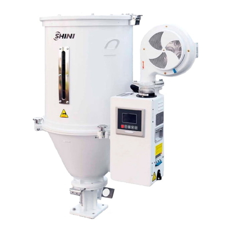
Shini SCD Series User manual

SCD Series
"All-in-One"Compact Dryer
Date: Jul. 2017
Version:Ver.F(English)


3(61)
Contents
1. General Description..................................................................................... 9
1.1 CodingPrinciple.................................................................................... 10
1.2 Features................................................................................................ 10
1.3 TechnicalSpecifications........................................................................ 11
1.3.1 TechnicalSpecification................................................................ 11
1.3.2 Specifications.............................................................................. 11
1.3.3 DryingCapacity........................................................................... 14
1.4 SafetyRegulations................................................................................ 16
1.4.1 SafetyRegulationsforthe Blowers.............................................. 16
1.4.2 SafetySignsand Labels.............................................................. 17
1.4.3 Transportation andStorageoftheMachine................................. 17
1.5 ExemptionClause................................................................................. 19
2. StructureCharacteristics and WorkingPrinciple.................................... 20
2.1 WorkingPrinciple.................................................................................. 20
2.2 RelativeHumidityand Dew-point.......................................................... 21
2.3 WhyChoose"All-in-One" CompactDryer............................................. 21
2.4 Options.................................................................................................. 22
3. Installation Testing..................................................................................... 25
3.1 Machine Location.................................................................................. 25
3.2 Air pipe and materialpipe connection................................................... 26
3.3 Waterconnections................................................................................ 27
3.3.1 CoolingWaterConnection........................................................... 27
3.3.2 CondensationDrainagePipe....................................................... 28
3.4 PowerConnectors................................................................................. 28
3.5 Air SupplyConnection........................................................................... 29
3.6 Notesof optionalmaterialstoragebin(MST-80U-OP).......................... 29
3.7 Notesof optionalHEPA........................................................................ 29
3.8 NotesforoptionalSHR-CP-3U.............................................................. 30
3.9 Cyclone Dust Collector.......................................................................... 31
3.10Oil Filter................................................................................................. 32

4(61)
3.11PlateHeatExchanger........................................................................... 32
4. Application and Operation......................................................................... 33
4.1 OperationProcedureforHMI................................................................ 33
4.1.1 Description of touchscreen......................................................... 33
4.1.2 Touchpanelappearerror............................................................ 33
4.1.3 Screen operationflowTable........................................................ 34
4.1.4 Menu Particular........................................................................... 34
4.1.4.1 SystemDefault Screen................................................... 34
4.1.4.2 DehumidifyingProcess ................................................... 35
4.1.4.3 PasswordUnlock ............................................................ 35
4.1.4.4 WorkingModesofRegeneration Heater(Dehumidifying
Function)38
4.1.4.5 WorkingModesofMaterialDrying .................................. 41
4.1.4.1 ConveyingMonitoring..................................................... 43
4.1.4.2 AlarmsFault Records...................................................... 44
5. Trouble-shooting ........................................................................................ 46
6. Maintenance and Repair............................................................................ 48
6.1 Filter& PressureRegulatingValve....................................................... 49
6.1.1 Filter& PressureRegulatingValveDrawing................................ 49
6.1.2 Filter& PressureRegulatingValveOperation steps.................... 49
6.2 Air Filters............................................................................................... 49
6.3 BlowerMotors....................................................................................... 50
6.3.1 DryingBlower.............................................................................. 50
6.3.2 RegenerationBlower................................................................... 50
6.3.3 ConveyingBlower........................................................................ 51
6.3.4 BlowerCleaning.......................................................................... 51
6.4 HeaterAssemblies................................................................................ 52
Warning!............................................................................................................. 52
6.5 TheUsefulLifeoftheKeyPartsoftheProduct.................................... 52
6.6 Honeycomb-rotor.................................................................................. 53
6.6.1 WhatisHoneycomb-rotor............................................................ 53
6.6.2 Installation of the Rotor................................................................ 53
6.7 EGO...................................................................................................... 55

5(61)
6.8 Cooler................................................................................................... 56
6.9 Dewpoint Monitor(Option)..................................................................... 56
6.9.1 Installation forDewpoint Monitor................................................. 56
6.9.2 Dew-point monitorsetting............................................................ 59
6.10MaintenanceSchedule.......................................................................... 60
6.10.1 GeneralMachineInformation ................................................ 60
6.10.2 Installation &Inspection........................................................ 60
6.10.3 DailyChecking ...................................................................... 60
6.10.4 WeeklyChecking................................................................... 60
6.10.5 MonthlyChecking.................................................................. 61
6.10.6 Half-yearlyChecking ............................................................. 61
6.10.7 YearlyChecking .................................................................... 61
6.10.8 3yearChecking.................................................................... 61
TableIndex
Table1-1: Specifications1(Fully-integraldesign)............................................. 11
Table1-2: Specifications2(Fully-integraldesign)............................................. 12
Table1-3: Specifications(Semi-integraldesign).............................................. 13
Table1-4: Dryingcapacity1............................................................................. 14
Table1-5: Dryingcapacity2............................................................................. 15
Table6-1:Theusefullifeof thekeypartsoftheproduct.................................. 52
PictureIndex
Picture1-1:Technicalspecifications................................................................. 11
Picture1-2: Safetyregulationsforthe blowers................................................. 16
Picture2-1: SCD workingprinciple................................................................... 20
Picture2-2: SCD-OP workingprinciple(Withplateheatexchanger) (Option).. 20
Picture3-1: Installation drawing........................................................................ 25
Picture3-2: Schematicdrawingofinstallation(Fully-integraldesign)............... 26
Picture3-3: Schematicdrawingofinstallation(semi-integraldesign)............... 26

6(61)
Picture3-4: Coolingwaterconnection.............................................................. 27
Picture3-5: Materialstagebinof opticalgradeMST-80U-OP.......................... 29
Picture3-6: High-efficiencyfilter....................................................................... 30
Picture3-7: Important noticesforusing............................................................ 31
Picture3-8: Installation diagramofcyclone dust collector................................ 31
Picture3-9: Installation diagramofoil filter....................................................... 32
Picture3-10:Plateheat exchangeroverfigure................................................. 32
Picture4-1: DescriptionofTouchScreen ......................................................... 33
Picture4-2: Screen Operation FlowTable........................................................ 34
Picture4-3: SystemInitialScreen..................................................................... 34
Picture4-4: DehumidifyingProcess Screen..................................................... 35
Picture4-5: PasswordInput Screen................................................................. 35
Picture4-6: DryingProcess .............................................................................. 36
Picture4-7: ParameterSettingMenu Screen................................................... 36
Picture4-8:TimeSettingScreen...................................................................... 37
Picture4-9: ParameterSetting......................................................................... 37
Picture4-10:ParameterSettingScreen........................................................... 38
Picture4-11: DryingProcess Screen................................................................ 38
Picture4-12: DehumidifyProcess Screen ........................................................ 39
Picture4-13:ParameterSettingScreen........................................................... 39
Picture4-14: DryingProcess Screen................................................................ 40
Picture4-15: DehumidifyProcess Screen ........................................................ 40
Picture4-16: DryingProcess Screen................................................................ 41
Picture4-17: DryingProcess Screen................................................................ 41
Picture4-18: Recipe SettingScreen................................................................. 42
Picture4-19: DryingProcess Screen................................................................ 42
Picture4-20: DryingProcess Screen................................................................ 43
Picture4-21: ConveyingMonitoringScreen..................................................... 43
Picture4-22: ConveyingSettingScreen ........................................................... 44
Picture4-23:AlarmFault Records.................................................................... 44
Picture6-1: Filter& Pressureregulatingvalvedrawing .................................... 49
Picture6-2: Air filters........................................................................................ 50
Picture6-3: Installation ofblowers.................................................................... 50
Picture6-4: Conveying blower.......................................................................... 51

7(61)
Picture6-5: Blowermotors............................................................................... 51
Picture6-6: Heaterassemblies......................................................................... 52
Picture6-7: Honeycombrotor........................................................................... 53
Picture6-8: Installation ofthe rotor................................................................... 54
Picture6-9: EGO .............................................................................................. 55
Picture6-10: Holesite...................................................................................... 56
Picture6-11:Partsof dew-point monitor........................................................... 57
Picture6-12: Copperjoint assemblyof originalmachine.................................. 57
Picture6-13: Installationseat ........................................................................... 57
Picture6-14: Installationfortransmitter............................................................ 58
Picture6-15: Connection of signalwire............................................................ 58
Picture6-16: Connection of dew-point monitor................................................. 59

8(61)

9(61)
1.General Description
Read thismanualcarefullybeforeoperationtopreventdamageofthe
machine orpersonalinjuries.
SCD seriesdehumidifying dryerpossessesthree functionsofdehumidification,
drying and two-stageconveying.It isverysuitablefordryingengineeringplastics
materialswithhygroscopicitysuchasPA,PC,PBT,PET.Amongthem,optics
SCD-OP couldbe usedinprocessingapplication oflens,LCD backlightboard
and discs, ithasdew-point of below-40 underidealcondition.
SCD-ES

10(61)
1.1CodingPrinciple
SCD xxxU / xxxH xxx
Option
DehumidfyingAir Quantity(m³/hr)
H: HoneycombRotor
HopperCapacity(L)
U: EuropeanType
ShiniCompact Dryer
1.2Features
●Combinethefunction ofdehumidifying, dryingand two-stageconveyingintoa
singleunit.
●SCD DryerLoadersareequippedwithhoneycombrotortoobtainstablelow
dew-point dryingair. It containstwomodels: semi-open andhermetic.
●Feedingsystemisequippedwithshut-off valvetoensurenosurplusraw
materialinhoppertubes.
●Microprocessorisavailableasstandardequipment.
●Heat preserved dryinghopperbarreladoptsdownblowpipe designand
collocateswithcyclone air exhaust toavoidheat lost and improvedrying
efficiency.
All serviceworkshouldbe carried out byaperson withtechnicaltrainingor
correspondingprofessionalexperience.The manualcontainsinstructionsforboth
handlingand servicing.Chapter6, whichcontainsserviceinstructionsintendedfor
serviceengineers. Otherchapterscontaininstructionsforthedailyoperator.
Anymodificationsofthemachinemustbe approved bySHINI inordertoavoid
personalinjuryand damagetomachine.Weshall not beliableforanydamage
causedbyunauthorized changeof themachine.
Ourcompanyprovidesexcellent after-salesservice. Shouldyou haveanyproblem
duringusingthemachine,pleasecontactthecompanyorthelocalvendor.
HeadquarterandTaipeifactory
Tel:(886)226809119
ShiniPlastics Technologies(Dongguan), Inc
Tel:(86)769 81116600
ShiniPlastics TechnologiesIndiaPvt.Ltd.
Tel:(91)250 3021166

11(61)
1.3Technical Specifications
1.3.1TechnicalSpecification
SCD HermeticSCD Semi-open SCD-OP
Picture1-1:Technicalspecifications
1.3.2Specifications
Table1-1: Specifications1(Fully-integraldesign)
Model SCD- 20U/30H-OP 40U/30H-OP 80U/50H-OP 120U/80H-OP
Ver. D D D D
Drying System
Dying Heater Power (kW) 3 3 3.9 6
Dying Blower Power (kW) 0.4 0.4 0.4 0.75
Hopper
Capacity (L) 20 40 80 120
Dehumidifying System
Regenerating Heater Power (kW)
3 3 3 3
Regenerating Blower Power(kW)
0.4 0.4 0.4 0.4
Dehumidifying Air quantity
(m3/hr) 30 30 50 80
Feeding System
Feeding Blower Power (kW) 1.5 1.5 1.5 1.5
Dia. of MaterialPipe (inch) 1.5 1.5 1.5 1.5
SHR-U-E Hopper (L) 3* 3* 3* 3*
SHR-U Hopper (L) 3 3 6 6
Dimensions
H(mm) 1400 1500 1670 1710
W(mm) 1050 1050 1240 1240
D(mm) 900 900 1000 1000
Weight (kg) 235 280 330 385
Note: 1)Plastic materials canbefullydriedbydryingair withdew-pointWereservethe righttochange
temperature ≤-20.Whenambienttemperature ≤-25 andspecifications withoutpriornotice.
relativehumidity≤-60%,thedrying airdewpointtemp. ≤-40.
2)"*" standsfor hopper receiverSHR-CP-U.
3)Power 3Ф,230/400/460 / 575VAC, 50/ 60Hz.

12(61)
Table1-2: Specifications2(Fully-integraldesign)
Model SCD- 20U/40H
40U/40H
80U/40H
120U/80H
160U/80H
160U/120H
230U/120H
300U/200H
450U/200H
Ver. C C C D D D C C C
Drying System
Dying Heater
Power (kW) 4 4 4 6 6 6 6 12 12
Dying Blower
Power
(kW, 50/60Hz)
0.12 0.12 0.12 0.75 0.75 0.75 0.75 1.5 1.5
Hopper
Capacity (L) 20 40 80 120 160 160 230 300 450
Dehumidifying System
Regenerating
Heater Power
(kW)(50/60Hz)
3 / 3 3 / 3 3 / 3 3 / 4 3 / 4 3 / 4 3 / 4 4 / 6 4 / 6
Regenerating
Blower Power
(kW, 50/60Hz)
0.4 0.4 0.4 0.4 0.4 0.4 0.4 0.4 0.4
Dehumidifying
Air quantity
(m3/hr,
50/60Hz)
40 40 40 80 80 120 120 200 200
Feeding System
Feeding Blower
Power (kW,
50/60Hz)
1.5 1.5 1.5 1.5 1.5 1.5 1.5 1.5 1.5
Dia. of Material
Pipe (inch) 1.5 1.5 1.5 1.5 1.5 1.5 1.5 1.5 1.5
SHR-U-E
Hopper (L) 3 3 6 6 6 6 12 12 12
SHR-U Hopper
(L) 3 3 6 6 6 6 12 12 12
Dimensions
H(mm) 1490 1550 1645 1990 1860 1860 2070 2160 2570
W(mm) 1000 1040 1105 1105 1190 1190 1190 1460 1460
D(mm) 880 880 880 875 875 875 875 1020 1020
Weight (kg) 280 295 325 340 385 505 515 565 595
Note:1)Plasticmaterialscanbe fullydriedbydryingair withdew-pointWereservethe righttochange
temperature ≤-20.Whenambient temperature ≤-25 andspecifications withoutpriornotice.
relativehumidity≤-60%,thedryingair dewpointtemp. ≤-40.
2)"*" standsfor hopper receiverSHR-CP-U.
3)Power 3Ф,230/400/460 / 575VAC, 50/ 60Hz.

13(61)
Table1-3: Specifications(Semi-integraldesign)
Model SCD- 600U/400H 750U/400H 900U/700H 1200U/700H
Ver. C C F F
Drying System
Drying Heater Power (kW) 18 18 24 24
Drying Blower Power (kW, 50/60Hz) 3.75 / 4.5 3.75 / 4.5 7.5 /8.6 7.5 /8.6
Hopper Capacity (L) 600 750 900 1200
Dehumidifying System
Regenerating Heater Power (kW) 7.2 7.2 10 10
Regenerating Blower Power
(kW, 50/60Hz)
0.75 / 0.9 0.75 / 0.9 1.5 / 1.8 1.5 / 1.8
Dehumidifying Air quantity
(m3/hr, 50/60Hz)
400 / 450 400 / 450 700 / 780 700 / 780
Feeding System
Feeding Blower Power (kW) 1.5 1.5 3.75 3.75
Dia. of MaterialPipe (inch) 1.5 1.5 2 2
SHR-U-E Hopper Receiver (L) 12 12 24 24
SHR-U Hopper Receiver (L) 12 12 24 24
Dimensions
H(mm) 2380 2610 2640 3070
W(mm) 1745 1745 2140 2140
D(mm) 1255 1255 1380 1380
Weight (kg) 640 690 850 900
Note:1)Plastic materialscanbefullydriedbydryingair withdew-pointWereservethe righttochange
temperature ≤-20.Whenambient temperature ≤-25 andspecifications withoutpriornotice.
relativehumidity≤-60%,thedryingair dewpointtemp. ≤-40.
2)"*" stands forhopperreceiver SHR-CP-U.
3)Power 3Ф,230 / 400/460/575VAC, 50/60Hz.

14(61)
1.3.3DryingCapacity
Table1-4: Dryingcapacity1
Material Drying
Temp.()
Drying
Time(hr)
Drying Capacity (kg/hr)
20U
/40H
40U
/40H
80U
/40H
120U
/80H
160U
/80H
160U
/120H
230U
/120H
300U
/200H
450U
/200H
ABS 80 2-3 16 27 35 105
CA 75 2-3 12 22 30 90
CAB 75 2-3 12 22 30 90
CP 75 2-3 16 27 35 106
LCP 150 4 11 20 27 80
POM 100 2 24 40 53 160
PMMA 80 3 17 29 38 115
IONOMER 90 3-4 10 17 22 66
PA6/6.6/6.10 75 4-6 9 14 19 58
PA11 75 4-5 10 17 23 69
PA12 75 4-5 10 17 23 69
PC 120 2-3 19 31 41 124
PU 90 2-3 17 29 38 115
PBT 130 3-4 13 23 31 93
PE 90 1 47 80 106 318
PEI 150 3-4 11 20 27 80
PET 160 4-6 11 19 25 75
PETG 70 3-4 11 20 27 80
PEN 170 5 13 23 30 90
PES 150 4 13 23 30 90
PMMA 80 3 17 29 28 115
PPO 110 1-2 19 33 44 133
PPS 150 3-4 11 20 27 80
PI 120 2 24 40 53 160
PP 90 1 39 66 88 265
PS(GP) 80 1 39 66 88 265
PSU 120 3-4 12 22 29 85
PVC 70 1-2 19 33 44 135
SAN(AS) 80 1-2 19 33 44 135
TPE 110 3 18 30 40 125
Note:1.PleaserefertoabovedryingcapacityofSCD machine,selecttherightmodel accordingtomaterial
usageofprocessingmachine.
2. PleaseconsultShini servicestaffformodel selection.

15(61)
Table1-5: Dryingcapacity2
Material Drying
Temp.()
Drying
Time(hr)
Drying Capacity (kg/hr)
600U
/400H
750U
/400H
900U
/700H 1200U /700H
ABS 80 2-3 210 355
CA 75 2-3 180 295
CAB 75 2-3 180 295
CP 75 2-3 210 355
LCP 150 4 160 365
POM 100 2 320 530
PMMA 80 3 230 383
IONOMER 90 3-4 133 220
PA6/6.6/6.10 75 4-6 115 192
PA11 75 4-5 138 230
PA12 75 4-5 138 230
PC 120 2-3 250 413
PU 90 2-3 230 383
PBT 130 3-4 186 310
PE 90 1 637 1062
PEI 150 3-4 160 265
PET 160 4-6 150 250
PETG 70 3-4 160 265
PEN 170 5 180 300
PES 150 4 180 300
PMMA 80 3 230 385
PPO 110 1-2 265 440
PPS 150 3-4 160 265
PI 120 2 320 530
PP 90 1 530 885
PS(GP) 80 1 531 885
PSU 120 3-4 173 290
PVC 70 1-2 265 442
SAN(AS) 80 1-2 265 442
TPE 110 3 250 413
Note: 1. Pleaserefer toabovedrying capacityof SCD machine, select the rightmodel according tomaterial
usageofprocessingmachine.
2. PleaseconsultShini servicestaffformodel selection.

16(61)
1.4SafetyRegulations
1.4.1SafetyRegulationsforthe Blowers
1)Undernormaloperation, the blowerswill generatehightemperature. Donot
touchblower's casetoavoidanyphysicalinjury.
2)Undernormaloperation, the blowermotor's current loadingwill increaseor
reduceaccordingtoairpressure's changeaccordingly.Whileinstallation,an
adequatemotoroverload protectionswitchshouldbe installedwithfull
loadingtest, toensureoperatingsafelyunderfull-loadingtoavoidmotor's
damage.
3)Toavoidanyblock materials, dust, powder, fiberparticlesandwaterdrops
enteringtheblower, and hencecausethedeficiencyof itsperformance.This
machine iswell designed withair filters,sopleasecleanupthefilterwithany
foreignparticles(recommendedtoclean up thisfilterweekly).
4)Clean the blowersbothinternalandexternalparts(especiallyforthe fan
coolingpath),andremovesurfacedust if necessary. Ifmoredustsare
accumulated, itwill causedeficiencyforventilation,temperaturerising,
vacuumpowerreduced, vibration increasedand soit will causemachine
brokedown.
5)Ball bearing, oil sealandsoundproof arebelongingtoconsumablepartsand
soit hasalifeperiod and equiresregularreplacement. Meanwhile, blade,
externalcase,andmetallicscreen etc. shouldbe replacedregularlyforbest
performance.
6)Undernormaloperation,iftheblowersarenotrunningsmoothlyorabnormal
noiseappeared. Pleaseimmediatelyshutdownthe machineforrepair.
Picture1-2: Safetyregulationsforthe blowers

17(61)
1.4.2SafetySignsand Labels
Danger!
Highvoltagedanger!
Thislabelisstuck onthe electricalboxes.
Attention!
Thislabelmeansthatthisarea shouldbetaken care!
Warning!
Hightemperature, takecareof hands!
Thislabelshouldbestick tothe shell of heater.
Attention!
Noneed forregularinspectionbecauseall theelectricalpartsinthe
controlunit arefixed tightly!
Note!
TheEGO over-temperatureprotection isonlyforprocess heater
protection,notformaterialprotection usage,the default settingshould
notbe changed.
1.4.3Transportation andStorageoftheMachine
Transportation:
1)SCD series"All-in-one"compactdryerarepackedincratesorplywood cases
withwooden palletat the bottom,suitableforquick positioningbyforklift.
2)Afterunpacked,castorsequipped on the machinecan beusedforeaseof
movement.
3)Donotrotatethemachineandavoidcollision withotherobjectsduring
transportationtoprevent improperfunctioning.
4)Thestructureofthemachineiswell-balanced,althoughitshouldalsobe
handled withcarewhenliftingthemachineforfearoffallingdown.
5)The machine anditsattachedpartscanbekeptatatemperaturefrom-25to
+55forlongdistancetransportationandforashortdistance,itcanbe
transported withtemperatureunder+70.

18(61)
Storage:
1)SCD series"All-in-One"compactdryershouldbestored indoorswith
temperaturekeptfrom5to40andhumiditybelow80%.
2)Disconnect all powersupplyand turnoffmainswitchand controlswitch.
3)Keepthe wholemachine,especiallytheelectricalcomponentsawayfrom
watertoavoidpotentialtroublescaused bythe water.
4)Plasticfilm shouldbeusedtoprotect the machinefromdust and rains.
Workingenvironment:
Indoorsinadryenvironmentwithmax. temperature+45andhumiditynomore
than80%.
Donotusethemachine:
1)Ifit iswithadamaged cord.
2)Onawet floororwhen it isexposed toraintoavoidelectricalshock.
3)Ifithasbeen dropped ordamageduntil itischecked orfixed byaqualified
serviceman.
4)Thisequipment works normallyinthe environmentwithaltitudewithin3000m.
5)At leastaclearanceof1msurroundingthe equipmentisrequired during
operation.Keep thisequipmentawayfromflammablesourcesatleasttwo
meters.
6)Avoidvibration, magneticdisturbanceat theoperationarea.
Rejectedpartsdisposal
When theequipmenthasrun outitslifetimeand can notbe used any
more,unplugthe powersupplyanddisposeofit properlyaccordingtolocalcode.
Firehazard.
Incaseoffire, CO2drypowderfireextinguishershouldbe applied.

19(61)
1.5Exemption Clause
Thefollowingstatementsclarifytheresponsibilitiesandregulationsbornbyany
buyeroruserwho purchasesproductsandaccessoriesfromShini(including
employeesandagents).
Shiniisexempted fromliabilityforanycosts,fees,claimsandlossescausedby
reasonsbelow:
1. Anycarelessorman-madeinstallations,operation andmaintenancesupon
machineswithoutreferringtothe Manualpriortomachineusing.
2. Anyincidentsbeyondhumanreasonablecontrols, whichincludeman-made
viciousordeliberatedamagesorabnormalpower,and machine faultscaused
byirresistiblenaturaldisastersincludingfire,flood,stormand earthquake.
3. Anyoperationalactionsthatarenotauthorized byShiniuponmachine,
includingaddingorreplacingaccessories, dismantling,deliveringorrepairing.
4. Employingconsumablesoroil mediathatarenotappointed byShini.

20(61)
2. Structure Characteristics andWorkingPrinciple
2.1WorkingPrinciple
Picture2-1: SCD workingprinciple
Picture2-2: SCD-OP workingprinciple(Withplateheatexchanger) (Option)
Dehumidifying: dampand hotair fromdrymaterialbarrelisblownintorotor
aftercooled.Moisturefromtheairisabsorbedbyrotorandisthenadsorbedby
regenerationheatingair. Twostrandsofairflowfunctiononthe rotor.And with
Other manuals for SCD Series
1
This manual suits for next models
4
Table of contents
Other Shini Dryer manuals

Shini
Shini SHD U-HD Series User manual

Shini
Shini SHD Series User manual

Shini
Shini CD SERIES User manual

Shini
Shini CD SERIES User manual

Shini
Shini MHD U Series User manual

Shini
Shini SHD-EB User manual

Shini
Shini SHD-E User manual

Shini
Shini SHD-EB Series User manual

Shini
Shini SHD Series User manual

Shini
Shini SCD-80Ux2/100H User manual