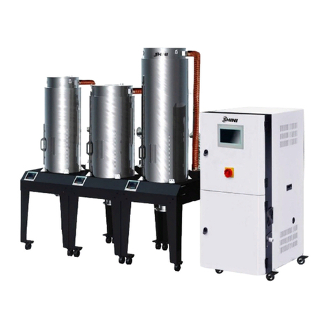
Shini SHD U-HD Series User manual

SHD-U-HD
HeatlessDehumidifyingHot-airDryer
Date:Jul.2012
Version: Ver.A(English)

2(49)

3(49)
Contents
1. General Description..................................................................................7
1.1 CodingPrinciple...................................................................................8
1.2 Feature.................................................................................................8
1.3 TechnicalSpecifications.....................................................................10
1.3.1 Specifications...........................................................................10
1.3.2 TechnicalSpecifications...........................................................10
1.4 SafetyRegulations.............................................................................11
1.4.1 SafetySignsand Labels...........................................................11
1.5 ExemptionClause..............................................................................11
2. StructureCharacteristics and WorkingPrinciple.................................13
2.1 WorkingPrinciple...............................................................................13
2.2 Drawingand PartsList.......................................................................14
2.2.1 StructuralDrawing....................................................................14
2.2.2 AssemblyDrawing....................................................................15
2.2.3 PartsList (SHD-40U~120U-HD)...............................................16
2.2.4 AssemblyDrawingofDryingDrying.........................................17
2.2.5 Parts& MaterialsListofDryChargingBarrel
(SHD-40U~120U-HD).........................................................................18
2.2.6 PartsDrawingofHot-air Recycler............................................19
2.2.7 Parts& MaterialsListofHot-air Recycler(SHD-40U~120U-HD).
.................................................................................................20
2.3 ElectricalDiagram..............................................................................21
2.3.1 ElectricalDiagram(SHD-40U~120U-HD).................................21
2.3.2 MainCircuit (SHD-40U~120U-HD)...........................................22
2.3.3 ControlCircuit (SHD-40U~120U-HD).......................................23
2.3.4 Thermocoupleand TerminalLayout (SHD-40U~120U-HD).....24
2.3.5 ComponentsLayout (SHD-40U~120U-HD)..............................25
2.3.6 ElectricalComponentsList (SHD-40U~120U-HD)...................26
2.3.7 MainElectricalComponentsDescription..................................28
2.4 OptionalAccessories.........................................................................29
2.4.1 FloorStand...............................................................................29
2.4.2 PneumaticShut-off Valveand SuctionBox..............................29

4(49)
3. Installation and Debugging.....................................................................31
3.1 AttentionsduringInstallation:.............................................................31
3.2 Installation Reference........................................................................31
3.2.1 Install directlyon amouldingmachine......................................31
3.2.2 Tobe Used withHopperLoaders.............................................32
3.3 PowerSupply.....................................................................................32
4. Application and Operation......................................................................33
4.1 Description of ControlPanel..............................................................33
4.2 Operationof theMachine...................................................................33
4.3 TemperatureSetting..........................................................................33
4.4 Intermittent DryingSetting..................................................................33
4.5 WeeklyTimeStartSetup...................................................................35
4.6 SystemClock Adjustment..................................................................37
4.7 EnableOne-weekAutomaticStart / StopTimer.................................37
4.8 Lock upthe Machine..........................................................................37
4.9 MeaningofErrorCode.......................................................................38
5. Troubleshooting.....................................................................................39
6. Maintenance and Repair.........................................................................40
6.1 Hot-air Recycler.................................................................................40
6.1.1 Exhaust-air Filter......................................................................41
6.2 GXW/GWAthermalRegenerationType ofAir Dryer..........................41
6.2.1 OperationInstruction................................................................42
6.2.2 Modeland Specification...........................................................42
6.2.3 TechnicalParameter................................................................43
6.2.4 Maintenance.............................................................................43
6.3 Blower................................................................................................48
6.4 MaintenanceSchedule.......................................................................48
6.4.1 About theMachine....................................................................48
6.4.2 Installation &Inspection............................................................48
6.4.3 DailyChecking..........................................................................48
6.4.4 WeeklyChecking......................................................................48
6.4.5 MonthlyChecking.....................................................................48
6.4.6 Half-yearlyChecking................................................................49

5(49)
Form Index
Chart 1-1 Specifications.................................................................................10
Chart 2-1 PartsList (SHD-40U~120U-HD).....................................................16
Chart2-2 Parts&MaterialsListofDryChargingBarrel(SHD-40U~120U-HD)
..........................................................................................................................18
Chart 2-3 Parts& MaterialsList of Hot-air Recycler(SHD-40U~120U-HD)...20
Chart 2-4 ElectricalDiagram(SHD-40U~120U-HD)......................................21
Chart 2-5 ElectricalComponentsList (SHD-40U-HD)....................................26
Chart 2-6 ElectricalComponentsList (SHD-80U/120U-HD)..........................27
Chart 4-1 Meaningof ErrorCode...................................................................38
PictureIndex
Picture1-1 SHD-U-HD(WithOptionalFloorStand).......................................10
Picture2-1 WorkingPrinciple.........................................................................13
Picture2-2 StructuralDrawing.......................................................................14
Picture2-3 AssemblyDrawing.......................................................................15
Picture2-4 AssemblyDrawingofDryingDrying.............................................17
Picture2-5 MainCircuit (SHD-40U~120U-HD)..............................................22
Picture2-6 ControlCircuit (SHD-40U~120U-HD)..........................................23
Picture2-7 ThermocoupleandTerminalLayout (SHD-40U~120U-HD).........24
Picture2-8 ComponentsLayout (SHD-40U~120U-HD).................................25
Picture2-9 Overload Relay............................................................................28
Picture2-10 PneumaticShut-offValveandSuctionBox...............................30
Picture3-1 InstallationSchemeof Injection MoldingMachine.......................31
Picture3-2 InstallationSchemeof ReceiverHopper......................................32
Picture4-1 Intermittent DryingSetting-Chart 1...............................................34
Picture4-2 Intermittent DryingSetting-Chart 2...............................................34
Picture4-3 Intermittent DryingSetting-Chart 3...............................................35
Picture4-4 One-weekAutomaticStart / StopTimer-Chart1..........................35
Picture4-5 One-weekAutomaticStart / StopTimer-Chart2..........................35
Picture4-6 One-weekAutomaticStart / StopTimer-Chart3..........................36

6(49)
Picture4-7 One-weekAutomaticStart / StopTimer-Chart4..........................36
Picture4-8 One-weekAutomaticStart / StopTimer-Chart5..........................37

7(49)
1. General Description
Read thismanualcarefullybeforeoperationtopreventdamageofthe
machine orpersonalinjuries.
TheHeatless DehumidifyingHot-air Dryerismadeofstainless steelandequipped
withathermalregeneration type ofair dryer, whichisabletodryplasticraw
materialswithstableand lowdew-point dryair withoutheatingandregeneration.
Featuresdryair down-flouringandcyclone exhaustanddoubleinsulatedlager
design, suitablefordringhygroscopicengineeringplastics whichishardfor
commonhopperdryer.Besides, it isalsofeatured byitslowpowerconsumption
and shortdryingtime.Thisseriesisabletoprovide machineswiththree feeding
capacitiesof 40L,80Land 120L.
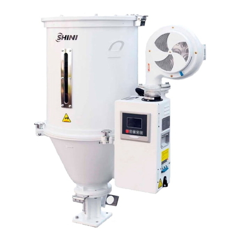
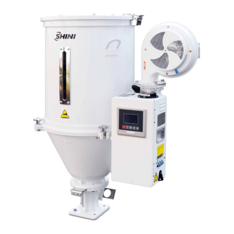
Model SHD-80U-HD+ FloorStandand Suction Box

8(49)
1.1CodingPrinciple
Note
*
CE=CEConformity
HD=Heatless Dehumidifying
P=For PolishedHopperInside
S
HD
-
xxx
U
-
xxx
Hopper Capacity(L)
EuropeanType
ShiniHopper Dryers
Option *
1.2Feature
Standardconfiguration
1)Microprocessorisused foraccuratetemperaturecontrol.
2)DigitalP.I.D. temperaturecontrolwithLEDdisplay.
3)Overheatprotection toensurereliableoperation.
4)7-dayautomaticstart/stoptimertoimproveenergysaving.
5)Unique designof downblowair pipe canspread hotair evenly, keeping
plastics aryand temperature. stabletoraisedryingefficiency.
6)ModelsSHD-80Uand abovehavematerialclearancedoortomaketheclean
moreconvenient and effective.
7)SHD-450Uand modelsbelowareequippedwithstainlesssteellining
aluminiumbase. SHD-600U~1200Uareequippedwithaluminiummagnetic
base.SHD-1500Uand modelaboveareequippedwithmanualbutterfly
valve.
8)ForSHD-900Umodelsandabove,floorstand isstandardequipment.
Accessoryoption
1)Cyclone dustseparator,exhaustair filter,magneticbaseandblowerinletfilter
areoptional.
2)Hotair recycler,suction box,hoppermagnetic,Ntype floorstand and storage
hopperareoptional.
3)SafetyprotectiveladderisoptionalforSHD-1500Uandmodelsabove.
4)SHD-U-HD heatless dehumidifyinghot-air dryer,fitwithheatless regenerative
device, whichcan supplydried air withrelativelowdew-pointforspeedup
materialsdrying.

9(49)
5)SHD-U-HD heatlessdehumidifyinghot-air dryer, standardwithhot air
recyclers,whichcan saveenergyeffectively. Withoutdustdischarging, which
ensuresenvironmentprotection.
All serviceworkshouldbe carried out byaperson withtechnicaltrainingor
correspondingprofessionalexperience.The manualcontainsinstructionsforboth
handlingand servicing.Chapter7, whichcontainsserviceinstructionsintendedfor
serviceengineers. Otherchapterscontaininstructionsforthedailyoperator.
Anymodificationsofthemachinemustbe approved bySHINI inordertoavoid
personalinjuryand damagetomachine.Weshall not beliableforanydamage
causedbyunauthorized changeof themachine.
Ourcompanyprovidesexcellent after-salesservice. Shouldyou haveanyproblem
duringusingthemachine,pleasecontactthecompanyorthelocalvendor.
HeadquarterandTaipeifactory
Tel:(886)226809119
ShiniPlastics Technologies(Dongguan), Inc
Tel:(86)769 81116600
ShiniPlastics TechnologiesIndiaPvt.Ltd.
Tel:(91)250 3021166

10(49)
1.3Technical Specifications
1.3.1Specifications
Chart 1-1 Specifications
Model
Loading
Capacity
(L)
Heater
Power
(kW)
Blower
(kW,50/
60Hz)
Dimensions
(mm)
HWD
Floor Stand*
(mm)
H1 W1 D1
Whole
Height
H2(mm)
Air Inlet
PipeDia.
ФA(inch)
Air Outlet
PipeDia.
ФA(inch)
Weight
(kg)
SHD-40U-HD
40 3 0.12/0.14
760 750 710
790 550 450 1300 2" 1.5" 70
SHD-80U-HD
80 3.9 0.12/0.14
940 840 820
840 730 560 1480 2.5" 2" 85
SHD-120U-HD
120 3.9 0.12/0.14
1210 840 820
840 730 560 1740 2.5" 2" 100
Note: 1) For polishedhopper inside, plus"P"atmodelbehind.Wereservethe right tochange
2) Net weightof machineincludesfloorstand.specificationswithoutpriornotice.
3) Items marked with “*”arefor selectivepairing.
4) Power supply: 3Φ,230 /400/ 460/ 575V, 50 / 60Hz.
1.3.2TechnicalSpecifications
Picture1-1 SHD-U-HD(WithOptionalFloorStand)

11(49)
1.4SafetyRegulations
Note!
Electricalinstallationshouldbe done byqualifiedelectrician only.Before
connectingtoACPowerSource, turnpowerswitchtoOFF position.
WhileACpowersourceisconnected,makesurespecificationsand
overload protectionratingofthepowerswitcharesuitableandreliable.
When the machine isundercareormaintenance, turnoff bothpower
switchand automaticoperationswitch.
1.4.1SafetySignsand Labels
Danger!
HighVoltage!
It isattachedtothecontrolbox.
Attention!
Thismarkremindsyoutobemorecareful.
Warning!
Hightemperaturesurfacemayburnhands!
Thislabelshouldbestick tothe shell of electricheatingbox.
Attention!
Noneed forregularinspectionbecauseall theelectricalpartsinthe
controlunit arefixed tightly!
1.5Exemption Clause
Thefollowingstatementsclarifytheresponsibilitiesandregulationsbornbyany
buyeroruserwho purchasesproductsandaccessoriesfromShini(including
employeesandagents).
Shiniisexempted fromliabilityforanycosts,fees,claimsandlossescausedby
reasonsbelow:
1. Anycarelessorman-madeinstallations,operation andmaintenancesupon
machineswithoutreferringtothe Manualpriortomachineusing.
2. Anyincidentsbeyondhumanreasonablecontrols, whichincludeman-made
viciousordeliberatedamagesorabnormalpower,and machine faultscaused

12(49)
byirresistiblenaturaldisastersincludingfire,flood,stormand earthquake.
3. Anyoperationalactionsthatarenotauthorized byShiniuponmachine,
includingaddingorreplacingaccessories, dismantling,deliveringorrepairing.
4. Employingconsumablesoroil mediathatarenotappointed byShini.

13(49)
2. Structure Characteristics andWorkingPrinciple
2.1WorkingPrinciple
Air blownout of dryingblowerbecamehightemperaturedryingair afterbeing
heated.Throughscreenprotectorandholescreen,hotair canbe equablly
dispersedinthe materialofstoragetank(See the picture). HARisoptionalso
the air enterdryingblowerafterbeingfilteredtoformaclosedloopcircle.
Drying
blower
Return airfilter
Drying
heater
drying storage
tank
Drying hopper
Dryinghopper
Shut-off suction box (Option) Inletfilter
Current limitpipe
Silencer
Non-return
valve
Non-return
valve
Exhaustfilter
Compressed airsource
Pneumatic
control
valve
Picture2-1 WorkingPrinciple

14(49)
2.2Drawing and PartsList
2.2.1 Structural Drawing
Names ofParts
1. Standardbase2. Controlbox3. AthermalRegenerationType ofAir Dryer
4. Heating case 5. Drying tank6. Hot-airRecycler
7. Exhaust-air Filter 8. Drying blower 9. AdjustableQuickCoupling
10. BackFilter 11. Front Filte12. Solenoidvalve
Picture2-2 StructuralDrawing

15(49)
2.2.2 AssemblyDrawing
Remarks:PleaserefertoMaterialList2.2.3forspecificexplanation ofthe Arabicnumbers
inPartsDrawing.
Picture2-3 AssemblyDrawing

16(49)
2.2.3PartsList (SHD-40U~120U-HD)
Chart 2-1 PartsList (SHD-40U~120U-HD)
Part No.
No.
Name SHD-40U-HD SHD-80U-HD SHD-120U-HD
1 Control cabinet door - - -
2 Electric elements’
mountingplate - - -
3 Control cabinet body - - -
4 Wirefixture’ssettingplate - - -
5 Dehumidifiercasebody - - -
6 Dehumidifiercasedoor - - -
7 Athermal regeneration type
of dryer YE90101100100 YE90102100000 YE90102100000
8 Front filter - - -
9 Coppercoupling - - -
10
Solenoid valve YE32213100000 YE32213100000 YE32213100000
11
Blower BM40025300450 BM40003000250
BM40003000250
12
Back filter - - -
13
Adjustablequickcoupling YW80061400000 YW80061400000
YW80061400000
14
Nozzle flange - - -
15
Hinge - - -
16
Air pipecoupling YW80061400200 YW80061400200
YW80061400200
17
Hot airpipe - - -
18
Pipe heater* BH70400300350 BH70803900250
BH70123900150
19
Hot-air pipe cover - - -
20
Hot-air recycler - - -
21
Drying tank - - -
22
Casesetting plate - - -
23
Shut-off plate YW09255000000 YW09255000000
YW09255000000
24
Standardbase BY10040000050 BY10040000050 BY10040000050
*means possiblebrokenparts.
** means easybroken part. and sparebackup issuggested.
Pleaseconfirmthe versionofmanualbeforeplacingthe purchase ordertoguaranteethat
the itemnumber ofthe sparepart isinaccordancewiththe realobject.

17(49)
2.2.4 AssemblyDrawing of Drying Drying
Remarks:PleaserefertoMaterialList2.2.5forspecificexplanation oftheArabic
numbersinPartsDrawing.
Picture2-4 AssemblyDrawingofDryingDrying

18(49)
2.2.5Parts& MaterialsListofDryChargingBarrel(SHD-40U~120U-HD)
Chart 2-2 Parts& MaterialsList of DryChargingBarrel(SHD-40U~120U-HD)
Part No.
No.
Name SHD-40U-HD SHD-80U-HD SHD-120U-HD
1 Hopper flange - - -
2 Outer hopper - - -
3 Internalhopper - - -
4 Insider fixed block - - -
5 Downblowing air pipe BL02045001820 BL02008000210 BL02012001420
6 Down-blowing pipe fixation
block BW21020400010 BW21081200010 BW21081200010
7 Heat preservation cover - - -
8 Upper ring YA30004000000 BA30801200110 BA30801200110
9 Material storage tank - - -
10 Sight glass frame - - -
11 Lid BL02004000020 BL02801200020 BL02801200020
12 Outer sight-glass frame - - -
13 Chargingentranceflange - - -
14 Latch - - -
15 Holdingscrew - - -
16 Sight glass door - - -
*means possiblebrokenparts.
** means easybroken part. and sparebackup issuggested.
Please confirmthe versionofmanualbeforeplacingthe purchaseordertoguaranteethat
the itemnumber ofthe sparepart isinaccordancewiththe realobject.

19(49)
2.2.6PartsDrawingofHot-air Recycler
Remarks:Please refertoMaterialList2.2.7forspecificexplanation oftheArabicnumbersin
PartsDrawing.
Picture2-6 PartsDrawingofHot-air Recycler

20(49)
2.2.7Parts& MaterialsListofHot-air Recycler(SHD-40U~120U-HD)
Chart 2-3 Parts& MaterialsList of Hot-air Recycler(SHD-40U~120U-HD)
Part No.
No.
Name SHD-40U-HD SHD-80U-HD SHD-120U-HD
1 Sight-glass - - -
2 Acryl - - -
3 Dust collection bin - - -
4 ButterflyNut YW69051600000 YW69051600000 YW69051600000
5 Filter YR50138000000 YR50181100000 YR50181100000
6 Fastener for filtering
barrel YR10016000000 YR10708000100 YR10708000100
7 Snap hook YW02003000400 YW02003000400 YW02003000400
8 Filterbarrel - - -
9 Filter’sSetting Plate
- - -
10
Nozzle Flange - - -
11
Exhaust-air Filter - - -
*means possiblebrokenparts.
** means easybroken part. and sparebackup issuggested.
Please confirmthe versionofmanualbeforeplacingthe purchaseordertoguaranteethat
the itemnumber ofthe sparepart isinaccordancewiththe realobject.
This manual suits for next models
3
Table of contents
Other Shini Dryer manuals

Shini
Shini SCD Series User manual

Shini
Shini SHD-EB User manual

Shini
Shini MHD U Series User manual

Shini
Shini CD SERIES User manual

Shini
Shini SHD-E User manual

Shini
Shini SHD-EB Series User manual

Shini
Shini SHD Series User manual

Shini
Shini CD SERIES User manual

Shini
Shini CD SERIES User manual

Shini
Shini SDL-U-HD Series User manual
Popular Dryer manuals by other brands

White Knight
White Knight C44AW Instructions for use

GE
GE DuraDrum GTDP400EM Dimensions and installation information

Samsung
Samsung DV25B6900H Series user manual

Electrolux
Electrolux IQ-Touch EIMGD60LT Use & care gude

Hotpoint
Hotpoint V3D01 Instructions for installation and use

Beko
Beko UD837RI user manual