Shini SHD-EB Series User manual

SHD-EB
BudgetHopperDryer
Date:Mar, 2017
Version: Ver.A


3(49)
Content
1. General Description.....................................................................................7
1.1 CodingPrinciple......................................................................................8
1.2 Feature....................................................................................................8
1.3 TechnicalSpecifications........................................................................10
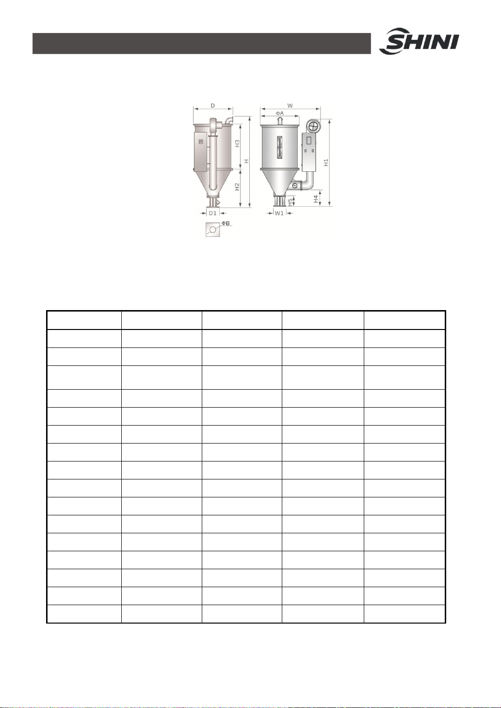
1.3.1 ExternalDimensions....................................................................10
1.3.2 Specification................................................................................10
1.4 SafetyRegulations................................................................................12
1.4.1 SafetySignsand Labels..............................................................12
1.4.2 Signsand Labels.........................................................................13
1.5 ExemptionClause.................................................................................13
2. StructureCharacteristics and WorkingPrinciple....................................14
2.1 WorkingPrinciple..................................................................................14
2.2 Drawingand PartsList..........................................................................15
2.2.1 AssemblyDrawing(SHD-25~75-EB)...........................................15
2.2.2 PartsList (SHD-25~75-EB).........................................................16
2.2.3 AssemblyDrawing(SHD-100/150-EB)........................................17
2.2.4 PartsList (SHD-100/150-EB).......................................................18
2.2.5 AssemblyDrawing(SHD-200-EB)...............................................19
2.2.6 PartsList (SHD-200-EB)..............................................................20
2.3 Circuit Diagram.....................................................................................21
2.3.1 Power, Diameter, Current............................................................21
2.3.2 ElectricalDiagram.......................................................................22
2.3.3 ElectricalComponentsLayout.....................................................25
2.3.4 ElectricalComponentsList..........................................................26
3. Installation and Debugging........................................................................40
3.1 Direct Installation...................................................................................40
3.2 FloorStand Installation.........................................................................41
3.3 Connectingthe PowerSource..............................................................41
3.4 TheHopperDryerTest.........................................................................42
3.5 Installation of the Options......................................................................42
3.5.1 Installation of Air-Exhaust Filter...................................................42
3.5.2 SuctionBoxInstallation...............................................................43

4(49)
3.5.3 BlowerInlet FilterInstallation.......................................................43
3.5.4 Hot Air RecyclerInstallation.........................................................44
4. Operation Guide.........................................................................................45
4.1 ControlPanel........................................................................................45
4.1.1 PanelOperation...........................................................................45
4.1.2 SettingTemperature....................................................................45
4.2 ControlPanelwithDryer.......................................................................47
4.2.1 PanelOperation...........................................................................48
4.2.2 TimerSetting...............................................................................48
5. Maintenance and Repair............................................................................49
5.1 Blower...................................................................................................49
6. Troubleshooting.........................................................................................49
TableIndex
Table1-1: Specification....................................................................................10
Table1-2: DryerDryingCapacity(kg/hr)(Selection Guide)................................11
Table2-1: PartsList (SHD-25~75-EB).............................................................16
Table2-2: PartsList (SHD-100/150-EB)...........................................................18
Table2-3: PartsList (SHD-200-EB)..................................................................20
Table2-4: ElectricalComponentsList (SHD-12-EB)........................................26
Table2-5: ElectricalComponentsList (SHD-12H-EB)......................................27
Table2-6: ElectricalComponentsList (SHD-25-EB)........................................28
Table2-7: ElectricalComponentsList (SHD-25H-EB)......................................29
Table2-8: ElectricalComponentsList (SHD-50-EB)........................................30
Table2-9: ElectricalComponentsList (SHD-50H-EB)......................................31
Table2-10:ElectricalComponentsList (SHD-75-EB)......................................32
Table2-11:ElectricalComponentsList (SHD-75H-EB)....................................33
Table2-12:ElectricalComponentsList (SHD-100-EB)....................................34
Table2-13:ElectricalComponentsList (SHD-100H-EB)..................................35
Table2-14:ElectricalComponentsList (SHD-150-EB)....................................36
Table2-15:ElectricalComponentsList (SHD-150H-EB)..................................37
Table2-16:ElectricalComponentsList (SHD-200-EB)....................................38

5(49)
Table2-17:ElectricalComponentsList (SHD-200H-EB)..................................39
PictureIndex
Picture1-1: ExternalDimensions......................................................................10
Picture2-1:WorkingPrinciple..........................................................................14
Picture2-2: AssemblyDrawing(SHD-25~75-EB).............................................15
Picture2-3: AssemblyDrawing(SHD-100/150-EB)..........................................17
Picture2-4: AssemblyDrawing(SHD-200-EB).................................................19
Picture2-5: ElectricalDiagram(SHD-12/12H-EB)............................................22
Picture2-6: ElectricalDiagram(SHD-25~150H-EB).........................................23
Picture2-7: ElectricalDiagram(SHD-200/200H-EB)........................................24
Picture2-8: ElectricalComponentsLayout.......................................................25
Picture3-1: Direct Installation...........................................................................40
Picture3-2: FloorstandInstallation..................................................................41
Picture3-3: Blower...........................................................................................42
Picture3-4: Left :Air-exhaust ElbowofDryer...................................................42
Picture3-5: European SuctionBox...................................................................43
Picture3-6: Shut-off Suction Box......................................................................43
Picture3-7: AIFBlowerInlet Filter....................................................................43
Picture3-8: HotAir Recycler............................................................................44
Picture4-1: ControlPanel.................................................................................45
Picture4-2:TemperatureController.................................................................45
Picture4-3: LeadSheet Fuse...........................................................................47
Picture4-4: OverheatingProtector...................................................................47
Picture4-5: ControlPanel(withtimer)..............................................................47
Picture4-6:Timer.............................................................................................48

6(49)

7(49)
1. General Description
Pleasereadthrough thisoperation manualbeforeusingthe machine to
prevent damagesofthemachineorpersonalinjuries.
SHD-50-EB

8(49)
1.1CodingPrinciple
1.2Feature
ŸAdopt hot air diffusertogainaneven hotair flowtoimprovedryingefficiency.
ŸHot air inletelbowdesigncan preventdust pilingup atbottomof thepipe
heaterssoastoavoidburning.
ŸAll materialcontact surfacesaremadeof stainless steeltoeliminatematerial
contamination.
ŸHopperseparatedfromitsbase,ensuringconvenient cleaning.
ŸAdoptsheat-insulatedblowertoprolongblowerlifespan.
ŸAll seriesofmodelsstandardequipped with7-daytimingandintermittent
operation function.add T”theendof themodelcoed.
ŸMax. dryingtemperatureis160 . Option high-temperaturemodel,and the
max. temperatureis180 , add "H"the endof the modelcode.

9(49)
All serviceworkshouldbe carried out byaperson withtechnicaltrainingor
correspondingprofessionalexperience.The manualcontainsinstructionsforboth
handlingand servicing.Chapter5, whichcontainsserviceinstructionsintendedfor
serviceengineers. Otherchapterscontaininstructionsforthedailyoperator.
Anymodificationsofthemachinemustbe approved bySHINI inordertoavoid
personalinjuryand damagetomachine.Weshall not beliableforanydamage
causedbyunauthorized changeof themachine.
Ourcompanyprovidesexcellent after-salesservice. Shouldyou haveanyproblem
duringusingthemachine,pleasecontactthecompanyorthelocalvendor.
HeadquarterandTaipeifactory
Tel:(886)226809119
ShiniPlastics Technologies(Dongguan), Inc
Tel:(86)769 81116600
ShiniPlastics TechnologiesIndiaPvt.Ltd.
Tel:(91)250 3021166

10(49)
1.3Technical Specifications
1.3.1ExternalDimensions
Picture1-1: ExternalDimensions
1.3.2Specification Table1-1: Specification
Mode SHD-25-EB SHD-50-EB SHD-100-EB SHD-200-EB
Heater(kW) 3/3.3* 3.9/4.2* 6/6.6* 12/15*
Blower(kW) 0.12 0.12 0.12 0.18
Loading
Capacity(kg) 25 50 100 200
H(mm) 1015 1145 1340 1332
H1(mm) 925 1045 1340 1332
H2(mm) 410 380 470 550
H3(mm) 460 520 725 975
H4(mm) 194 206 233 184
H5(mm) 150 150 158 158
W(mm) 725 840 955 1230
D(mm) 405 490 605 770
D1(mm) 158 158 238 238
W1(mm) 148 148 238 238
ФA (mm) 385 470 595 750
ФB (mm) 55 55 90 90
Net weight (kg) 40 45 70 100
Note:1)Aboveloading capacityis basedon pelletmaterial of0.65kg/Lin bulkdensityand3~5mmindiameter.
2) *”Option for high-temperaturemodel,and the max. temperatureis180°C.
3) Power: 3Φ, 230/400/460/575VAC, 50/60Hz.

11(49)
Table1-2: DryerDryingCapacity(kg/hr)(Selection Guide)
Mode
Material SHD-25-EB
SHD-50-EB
SHD-100-EB
SHD-200-EB
Drying
Time Drying
Temp.
Polystyre(PS)
20 50 100 200 0.75hrs
80
Polyethylen
(PE) 20 50 100 200 0.75hrs
80
Polypropyrene
(PP) 20 50 100 200 0.75hrs
80
Polystyrence
H·D 14 38 80 150 1hrs 80
ABS 8 20 40 80 1hrs 80
Nylon 11,124 10 20 35 4hrs 75
Nylon6/6,6/10 3.2 8 16 30 5hrs 75
Nylon 6 2 5 10 20 7hrs 75
Acrylic fiber 6 12 30 60 2.5hrs 80
Cellulose
acetate 6 17 35 70 2.25hrs
75
Butyrate 10 25 50 100 1.5hrs -
Polycarbonate
(PC) 4 10 20 40 3hrs 120
Rigid PVC12 30 60 120 1.25hrs
70
Notes:Basedonrelativehumidity65%withambient temperatureof20 ,moisurecontentafter dryingcan be
0.2% roless.

12(49)
1.4SafetyRegulations
1.4.1SafetySignsand Labels
Note!
Electricalinstallation shouldbe done byqualifiedelectrician only.
BeforeconnectingtoACPowerSource,turnpowerswitchtoOFF
position.WhileACpowersourceisconnected,makesurespecifications
and overload protection ratingofthepowerswitcharesuitableand
reliable.Whenthemachine isundercareormaintenance,turnoff both
powerswitchandautomaticoperation switch.
Danger!
Highpresscure!
It isattached tothe controlbox.
Warning!
Hightemperaturesurfacemayburnhands!
It isattached on the coverofpipe heater.
Attention!
Thismarkremindsyoutobemorecareful!
Warning!
Hightemperaturesurfacemayburnhands!
Thislabelshouldbestick tothe shell of electricheatingbox.

13(49)
1.4.2Signsand Labels
Protectiondeviceactivateswhen overheat
occurs;afterfaultsaredischarged,press
blue keytoresetandturnontheswitchto
Restart operation.
Push-and-pull switchforshut-off plate:
I: Means"Pull"
O: Means"Push"
Regularlyclean the filterscreen toavoid
insufficient dryingcaused byblocking
1.5ExemptionClause
Thefollowingstatementsclarifytheresponsibilitiesandregulationsbornbyany
buyeroruserwho purchasesproductsandaccessoriesfromShini(including
employeesandagents).
Shiniisexempted fromliabilityforanycosts,fees,claimsandlossescausedby
reasonsbelow:
1. Anycarelessorman-madeinstallations,operation andmaintenancesupon
machineswithoutreferringtothe Manualpriortomachineusing.
2. Anyincidentsbeyondhumanreasonablecontrols, whichincludeman-made
viciousordeliberatedamagesorabnormalpower,and machine faultscaused
byirresistiblenaturaldisastersincludingfire,flood,stormand earthquake.
3. Anyoperationalactionsthatarenotauthorized byShiniuponmachine,
includingaddingorreplacingaccessories, dismantling,deliveringorrepairing.
4. Employingconsumablesoroil mediathatarenotappointed byShini.

14(49)
2. Structure Characteristics andWorkingPrinciple
2.1WorkingPrinciple
Picture2-1:WorkingPrinciple
Inthe dryingprocess,hotair withconstanttemperatureisblownbythe drying
blower2ofSHD intothe dryinghopper7todrythe materials.Moisturewill be
separated outandtakenawaybyhot air, thustogainasatisfied dryingeffect.
Air blownoutofblowerviahotair pipe4becamehightemperaturedryingair
afterbeingheated.Throughshadeseparator5andscreenprotector6,hotair
can be equablydispersed tothematerialinstoragetank(seepicture).Hotair
recyclerisoptionalsotheair entered dryingblower7afterbeing filteredby
returnair will getintothe dryingblower2toformaclosedloopcircle,which
saveselectricity.

15(49)
2.2Drawing and PartsList
2.2.1AssemblyDrawing(SHD-25~75-EB)
Remarks Pleaserefer tomaterial list 2.2.2for specificexplanationoftheArabicnumbersin partsdrawing.
Picture2-2: AssemblyDrawing(SHD-25~75-EB)

16(49)
2.2.2PartsList (SHD-25~75-EB)
Table2-1: PartsList (SHD-25~75-EB)
Part NO.
NO. Name SHD-25-EB SHD-50-EB SHD-75-EB
1Control box** BH31002509550
BH31005006550
BH31007506550
2Hot-air pipe** BA10002500410
BA10005000610
BA10005000610
Pipe heater*(SHD) BH70250300150
BH70500300150
BH70750300050
3Pipe heater**(SHD-H) BH70253300010
BH70007500510
BH70754800010
4Blower* YM40002501150
YM40000300900
YM40000300900
5Storage hopper BK01002500020
BK01005000020
BK01007500020
6Rear hinge at cover YW06125040000
YW06125040000
YW06125040000
7Exhaust pipe BA10251000010
BA10251000010
BA10251000010
8Handle hookYW00251000000
YW00251000000
YW00251000000
9Handle YW00121000000
YW00121000000
YW00121000000
Hoppercover YW09002500000
YW09005000100
BL01007500020
10Cover fastenerYR10002500100
YR10005000100
YR10010040000
Sight glassYW09000600000
YW09000600000
YW09000600000
Sight glass acryl YR40001200000
YR40001200000
YR40001200000
11Sight glass
Fastener YR40000600000
YR40000600000
YR40000600000
12Screenseparator** BL01002500620
BL01005001120
BL01007500120
13Shade separator** BL01002501520
BL01005000320
BL01007500320
14Rear hinge at hopper YW09125000100
YW09125000100
YW09125000100
Hopper BA10002500210
BA10005000110
BA10007500110
15Hopper fastener YR10002500200
YR10005000200
YR10010000200
16Base** BY10050000550
BY10050000550
BY10050000550
17Star pinYW09085400000
YW09085400000
YW09085400000
Star nutYW09675100000
YW09675100000
YW09675100000
18Star screwYW09051600100
YW09051600100
YW09051600100
*means possiblebrokenparts.
** means easybroken partsand sparebackup issuggested.
Please confirm theversionofmanual beforeplacingthe purchaseordertoguaranteethatthe
itemnumber ofthe sparepart isinaccordancewiththe realobject.

17(49)
2.2.3AssemblyDrawing(SHD-100/150-EB)
Remarks Pleaserefer tomaterial list 2.2.4for specificexplanationoftheArabicnumbersin partsdrawing.
Picture2-3: AssemblyDrawing(SHD-100/150-EB)

18(49)
2.2.4PartsList (SHD-100/150-EB)
Table2-2: PartsList (SHD-100/150-EB)
Part NO.
NO. Name SHD-100-EB SHD-150-EB
1Control box* BH31010006550 BH31015006550
2Hot-air pipe** BA10010000610 BA10010000610
Pipe heater**(SHD) BH70103800050 BH70153800050
3Pipe heater**(SHD-H) BH70153800050 BH70150720010
4Blower* YM40000400900 YM40000400900
5Storage hopper BK01010000020 BK01015000020
6Rear hinge at cover YW06102000000 YW06102000000
7Exhaust pipe BA10251000010 BA10251000010
8Handle hook YW00251000000 YW00251000000
9Handle YW00121000000 YW00121000000
Hoppercover BL01100700720 BL01100700720
10Cover fastener YR10010040000 YR10010040000
Sight glass YW09000600000 YW09000600000
Sight glass acryl YR40001200000 YR40001200000
11Sight glass fastener YR40000600000 YR40000600000
12Screenseparator** BL01010000120 BL01010000120
13Shade separator** BL01010000320 BL01010000320
14Rear hinge at hopper YW09102000100 YW09102000100
Hopper BA10010000110 BA10010000110
15Hopper fastener YR10010000200 YR10010000200
Star nutYW09115600000 YW09115600000
16Star screwYW09100000000 YW09100000000
17Star pinYW09085400000 YW09085400000
18Base** BY10200000050 BY10200000050
*means possiblebrokenparts.
** means easybroken partsand sparebackup issuggested.
Please confirmtheversionofmanualbeforeplacingthe purchase ordertoguaranteethatthe
itemnumber ofthe sparepart isinaccordancewiththe realobject.

19(49)
2.2.5AssemblyDrawing(SHD-200-EB)
Remarks Pleaserefer tomaterial list 2.2.6for specificexplanationoftheArabicnumbersin partsdrawing.
Picture2-4: AssemblyDrawing(SHD-200-EB)

20(49)
2.2.6PartsList (SHD-200-EB)
Table2-3: PartsList (SHD-200-EB)
NO. Name Part NO.
1Control box** BH31020006950
2Hot-air pipe** BA10020000610
3Pipe heater**(SHD) YW90001201500
4Blower* YM40000500900
5Rear hinge at cover YW09102000100
6Storage hopper BK01020000020
Hoppercover BW09020000020
7Cover fastener YR10002500200
8Exhaust pipe BA10020000210
9Handle hook YW00251000000
10Handle YW00121000000
Sight glassYW09000600000
Sight glass acryl YR40001200000
11Sight glass fastener YR40000600000
12Screenseparator** BL01020000120
13Shade separator** BL01020000320
Hopper BA10020000110
14Hopper fastener YR10002500200
Star nutYW09115600000
15Star screwYW09100000000
16Star pinYW09085400000
17Base** BY10200000050
*means possiblebrokenparts.
** means easybroken partsand sparebackup issuggested.
Pleaseconfirmthe versionofmanualbeforeplacingthe purchase ordertoguaranteethat
the itemnumber ofthe sparepart isinaccordancewiththe realobject.
This manual suits for next models
4
Table of contents
Other Shini Dryer manuals

Shini
Shini CD SERIES User manual

Shini
Shini SHD-EB User manual

Shini
Shini CD SERIES User manual

Shini
Shini SHD-E User manual

Shini
Shini SHD U-HD Series User manual

Shini
Shini CD SERIES User manual

Shini
Shini SDL-U-HD Series User manual

Shini
Shini SHD Series User manual

Shini
Shini SCD Series User manual

Shini
Shini SHD Series User manual
Popular Dryer manuals by other brands

Miele
Miele PT 5136 OS OPERATING AND INSTALLATION Manual

Whirlpool
Whirlpool WED5800 installation instructions

LG
LG RC8055AP3Z manual

Mediclinics
Mediclinics M14ACS-UL Installation and operating manual

Alliance Laundry Systems
Alliance Laundry Systems D355IE1B Installation and operation

Beko
Beko DRX923W user manual