Shini CD SERIES User manual

CD Series
CabinetDryer
Date:Feb,2019
Version:Ver.B(English)


3(21)
Contents
1. General Description..................................................................................... 5
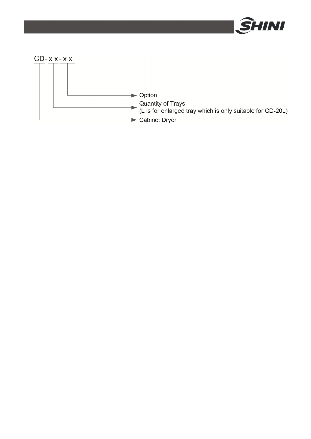
1.1 CodingPrinciple......................................................................................6
1.2 Feature....................................................................................................6
1.3 TechnicalSpecifications..........................................................................8
1.3.1 Outline Drawing.............................................................................8
1.3.2 Specifications................................................................................8
1.4 SafetyRegulations..................................................................................9
1.4.1 SafetySignsand Labels................................................................9
1.4.2 Transportation andStorageoftheMachine...................................9
1.5 ExemptionClause................................................................................. 11
2. StructureCharacteristics and WorkingPrinciple.................................... 12
2.1 MainFunctions...................................................................................... 12
2.2 WorkingPrincipleIllustration................................................................. 12
3. Installation and Debugging........................................................................ 13
3.1 AttentionsDuringInstallation................................................................ 13
3.2 Machine InsTallation Distance............................................................. 13
3.3 Check theRotationDirection ofBlower................................................. 14
4. Application and Operation......................................................................... 15
4.1 Test....................................................................................................... 15
4.2 SettingTemperature............................................................................. 15
4.2.1 KeysOperatureInstruction.......................................................... 16
4.3 Adjustment of Air Rate.......................................................................... 17
4.4 Start-up TimerSetting........................................................................... 17
4.5 SettingtheOver-thermalProtector........................................................ 18
5. Trouble-shooting ........................................................................................ 19
6. Maintenance and Repair............................................................................ 20
6.1 MaintenanceSchedule.......................................................................... 21
6.1.1 About theMachine....................................................................... 21
6.1.2 ElectricalInstallation.................................................................... 21

4(21)
6.1.3 DailyChecking............................................................................. 21
6.1.4 WeeklyChecking......................................................................... 21
6.1.5 MonthlyChecking........................................................................ 21
TableIndex
Table1-1: Specifications.................................................................................... 8
PictureIndex
Picture1-1: Outline Drawing............................................................................... 8
Picture2-1:WorkingPrincipleIllustration ......................................................... 12
Picture3-1: MachineInsTallationDistance...................................................... 13
Picture3-2: BlowerInlet / Outlet....................................................................... 14
Picture4-1:Temp.Controller............................................................................ 15
Picture4-2: Adjustment ofAir Rate................................................................... 17
Picture4-3: Start-up TimerSetting................................................................... 18
Picture4-4: Settingthe Over-thermalProtector................................................ 18

5(21)
1. General Description
Read thismanualcarefullybeforeoperationtopreventdamageofthe
machine orpersonalinjuries.
Forbiddentoprocess flammableortoxicmaterial!
CD seriesofcabinetdryeraremostlyusedforsimultaneousdryingofdifferent
kindsofpolymersinsmall quantitiesorfordryingmaterialsfortrialmoulding.They
can alsobeappliedinelectronicengineering,electroplating,pharmacy,paint
baking, printingindustries, etc. forpreheatingordryingrelated products.
Model: CD-9Model: CD-20-HT

6(21)
1.1CodingPrinciple
1.2Feature
lAccurateP.I.D.temperaturecontroltoachieveaneven dryingeffect.
lAir-proofed insulativedoorcanmaintaintemperatureconstantlyinside to
reduceenergyconsumption.
lStainlesssteeltrayandlinerbringnocontaminationtomaterials.
lUnique designof adjustableair inletandexhaust.
l24 hourstimer, easytooperate.
lOverheat protectorcanprevent excessivedrying.
lMotoroverload relay.
lVisiblealarm toindicatetroublesimmediately
lPowerwouldbe automaticallycut offwhen dryingtemperatureexceeds
set deviation value toprotect thermalfuse.
All serviceworkshouldbe carried outbyaperson withtechnicaltrainingor
correspondingprofessionalexperience. Themanualcontainsinstructionsforboth
handlingandservicing.Chapter6,whichcontainsserviceinstructionsintendedfor
serviceengineers. Otherchapterscontaininstructionsforthedailyoperator.
Anymodificationsofthe machine mustbeapproved bySHINIinordertoavoid
personalinjuryand damagetomachine.Weshall notbe liableforanydamage
causedbyunauthorized changeof themachine.
Ourcompanyprovidesexcellentafter-salesservice.Shouldyou haveany
problemduringusingthe machine,pleasecontactthecompanyorthe local
vendor.

7(21)
HeadquarterandTaipeifactory
Tel:(886)226809119
ShiniPlastics Technologies(Dongguan), Inc
Tel:(86)769 81116600
ShiniPlastics TechnologiesIndiaPvt.Ltd.
Tel:(91)250 3021166

8(21)
1.3Technical Specifications
1.3.1Outline Drawing
Picture1-1: Outline Drawing
1.3.2Specifications
Table1-1: Specifications
Model CD-5 CD-9 CD-20 CD-20L CD-5-HT
CD-9-HT
CD-20-HT
CD-20L-HT
Ver. B B B B B B B B
Heater(kW)
4 4.5 9 18 4 4.5 9 8
Blower
(kW,50/60
Hz)
0.37/0.55
0.37/0.55
1.5 1.5 0.37/0.55
0.55 1.5 1.5
Highest
Temp.()
200 200 200 200 250 250 250 250
Tray
Quantity 5 9 20 20 5 9 20 20
Total
Capacity
(kg)
50 90 200 450 50 90 200 450
OuterDimensionsH WD(mm)
- 1200 800
610
1440 800
610
1700 1210
760
1865 1800
1060
1380 860
731
1640 920
731
1887 1310
1032
2052 1900
1232
InnerDimensionsH1 W1 D1(mm)
- 660 600
550
900 600
550
1000 990
800
1200 1600
1000
660 600
550
900 600
550
1000 990
800
1200 1600
1000
Weight(kg)
150 180 415 550 200 252 587 778
Notes: 1)"HT" standsforheatinsulation model,thesurfacetemperatureWereservetherighttochange
of whichwill notbemorethan 80 when setuptemperatureis250 .specifications withoutpriornotice.
2)Whendryingtemperatureis below150 ,"HT" modelscankeepinternaltemperatureaccuracy
of ±5,when itisabove150 ,internal temperatureaccuracyis±12 .
3)Aboveloading capacityisbased onpelletmaterial of0.65kg/L(5.4Ib/gal)inbulkdensityand 3~5mm(0.12~0.2inch)in
diameter.
4)Power: 3Φ,230/400/460/575VAC,50/60Hz.

9(21)
1.4SafetyRegulations
1.4.1SafetySignsand Labels
Pleaseabidebythe safetyguide when you operatethe machine soastoprevent
damageof themachineandpersonalinjuries.
All electricalcomponentsshouldbe installedbyqualified electricians.
Turnoff mainswitchand controlswitchduring repair and maintenance.
Warning! Highvoltage!
Thismarkisattachedon the coverof thecontrolbox.
Warning! Becareful!
Be morecarefulwhen thismarkappears.
Attention!
Noneedforregularinspectionbecauseall theelectricalpartsinthecontrol
unit arefixed tightly!
1.4.2Transportation andStorageoftheMachine
Transportation andstorageofthemachine
1)CD seriesarepacked incratesorplywood caseswithwooden palletatthe
bottom,suitableforquick positioningbyforklift.
2)Afterunpacked,castorsequippedonthe machine can be usedforeaseof
movement.
3)Donotrotatethemachine and avoidcollision withotherobjectsduring
transportation toprevent improperfunctioning.
4)Thestructureof themachineiswell-balanced, althoughitshouldalsobe
handled withcarewhenliftingthemachine forfearoffallingdown.
5)Themachineand itsattached partscanbekept atatemperaturefrom
-25 to+55 forlong distancetransportation andforashort distance, it
can betransported withtemperatureunder+70 .
Storage
1)CD seriesshouldbestored indoorswithtemperaturekeptfrom5 to40

10(21)
and humiditybelow80%.
2)Disconnectall powersupplyand turnoffmainswitchand controlswitch.
3)Keepthewholemachine,especiallythe electricalcomponentsawayfrom
watertoavoidpotentialtroublescaused bythe water.
4)Plasticfilmshouldbeused toprotect the machine fromdustandrains.
Workingenvironment
1)Indoorsinadryenvironment withmax. temperature+45 andhumidity
no morethan80%.
Donotusethemachine:
1)If it iswithadamaged cord.
2)Onawetfloororwhenit isexposedtoraintoavoidelectricalshock.
3)If ithasbeendroppedordamageduntil it ischeckedorfixed byaqualified
serviceman.
4)Thisequipment works normallyinthe environment withaltitudewithin
3000m.
5)At leastaclearanceof1msurroundingtheequipment isrequiredduring
operation.Keep thisequipment awayfromflammablesourcesat least two
meters.
6)Avoidvibration, magneticdisturbanceat the operationarea.
Rejectedpartsdisposal
When the equipmenthasrunoutitslifetimeandcannotbe used anymore,
unplugthepowersupplyand disposeof it properlyaccordingtolocalcode.
Firehazard
Incaseoffire, Co2drypowderfireextinguishershouldbe applied.

11(21)
1.5Exemption Clause
Thefollowingstatementsclarifythe responsibilitiesand regulationsbornbyany
buyeroruserwho purchasesproductsandaccessoriesfromShini(including
employeesandagents).
Shiniisexemptedfromliabilityforanycosts,fees,claimsandlossescausedby
reasonsbelow:
1)Anycareless orman-madeinstallations,operation and maintenances
uponmachineswithoutreferringtotheManualpriortomachine using.
2)Anyincidentsbeyond human reasonablecontrols, whichinclude
man-made viciousordeliberatedamagesorabnormalpower, and
machine faultscausedbyirresistiblenaturaldisastersincludingfire,flood,
stormandearthquake.
3)Anyoperationalactionsthatarenotauthorized byShiniuponmachine,
includingaddingorreplacingaccessories,dismantling, deliveringor
repairing.
4)Employingconsumablesoroil mediathatarenotappointed byShini.

12(21)
2. Structure Characteristics andWorkingPrinciple
2.1MainFunctions
Forcabinetdryer,materialstobe dried areplaced on the stainlesssteelmade
moveablematerialtrays.Duringoperation,processair will flowtoheatingwire
and be heated uptorequired temperature,then flowthroughamanifoldwith
evenlyscattered holes.Moistureair issentoutthroughair exhaustport. It is
designed toachieveaneven dryingeffect.
2.2WorkingPrincipleIllustration
Names ofParts
1. Heating Coil 2.Air Inlet Blower3. Air Chamber
4. Multi-vane Impeller5. Paint-bakedCover6. Air Inlet
7. Air Exhaust8.Stainless SteelTray9. Heat-resistant Layer
Picture2-1:WorkingPrincipleIllustration

13(21)
3.Installation and Debugging
Install the CD CabinetDryerataproperplacewhereiseasyforserviceand
maintenance.
3.1Attentions During Installation
1)Makesurevoltageand frequencyofthe powersourcecomplywiththose
indicatedonthemanufacture's plate, whichisattached tothe machine.
2)Powercableand earthconnectionsshouldconform withlocalregulations.
3)Useindependent powercableand ON/OFF switch.The cable's size
shouldnotsmallerthanthoseappliedinthe controlbox.
4)Thepowercableconnection terminalsshouldbe tightenedsecurely.
5)Themachinerequiresa3-phase4-wirepowersource, connect the power
lead (L1, L2,L3)tothe livewires, and theearth(PE)totheground.
6)Powersupplyrequirements:
Mainpowervoltage: ±5%
Mainpowerfrequency: ±2%
7)Pleaserefertoelectricaldrawingofeachmodeltoget thedetailed power
supplyspecifications
3.2MachineIns Tallation Distance
Picture3-1: MachineInsTallationDistance
Note:Keepthemachine2Mfrom thecombustibledistance.

14(21)
3.3Checkthe RotationDirectionofBlower
1)Check whetherthewind directionofinletandoutletonthetwosidesofoven is
right.
2)If therotation directionisnot right:
a.Stop the machine.
b.Turnoffthe mainswitch.
c.Changeanytwolinesofthemainpowersupply's three lines.
d.Stop the machine, andcheck itagain.
Picture3-2: BlowerInlet / Outlet

15(21)
4.Application and Operation
Openthedistributionboxand connectthe powersourceinaccordancewithwiring
diagram.Makesurethatthepowervoltageisincompliancewiththe required
specifications.
Notes:Beforeconnecting, themainswitchand heatswitch
shouldbeoff.
4.1Test
Afterall wiresareconnected,turnthe mainswitchand theheaterswitchto “ON”,
then the pilotlamplight, observeifthe rotatingdirection ofblowerisconsistent
withthe arrow. If not, exchangeanytwopowercables.
4.2SettingTemperature
Firstlypress key ,thenpress keys toadjusttemperature,finallypress
confirmativekey toconfirmtheadjusting.Usetemperatureadjustortogether
withmaterialdrythermometertosetthe temperature. Afterheatingforaperiodof
time,the yellowlightand red lightwill flashalternatively,whichindicatesthatthe
settingtemperaturevalue hasbeenreached,atthattimethe actualtemperature
oftemperaturecontrollerandsettingtemperaturearethesame.
Picture4-1:Temp.Controller

16(21)
4.2.1KeysOperatureInstruction
Parameterlayerselection key
1)Ifselect thiskeyundercommoncondition,systemwill enterParameter
layerselection mode,and press thiskeyagaintoSelectparameter
layer. Ifwant toenterparametermode,pleasePress key.
2)Ifpressthiskeyunderparametermode, systemwill out of the
parametermode andentertheparameterlayerselectionmode.
3)Undersettingmode,press theselectionkeytostoretheparameters
and outofthesettingmode,entertheparametermode.
4)Underall modes,press thiskey for2secondstoskipback to
commoncondition.
Settingkeys
1)Undercommonmode, press settingkeytoset the'settingvalue'
directly.
2)Underparameterlayerselection mode, press settingkeytoskipback
the last parameterlayer.
3)Underparametermode,press thiskey, systemwill entersettingmode,
and maysettheparameters.
4)Undersettingmode,press settingkeytoselect thesettingnumbersor
storetheparametersand skipback theparametermode.
Upkey
1)Underparameterlayerselection mode, press upkeytoenter
parametermode.
2)Underparametermode, press up keytoselect theparametersof this
parameterlayer.
3)Undersettingmode,press upkeytoincreasethe parameters' value
until their upperlimit.
Downkey
1)Underparameterlayerselection mode, press downkeytoenter
parametermode.

17(21)
2)Underparametermode,press downkeytoselecttheparametersof
thisparameterlayer.
3)Undersettingmode,press downkeytoincreasetheparameters' value
until their lowerlimit.
4.3Adjustment of Air Rate
Adjustmentofair rateisthemostimportantfactorforthedryingresult, should
adjusttheair outletandinlet when dryingdifferentmaterial.
Forexample:
1)When heatandbrakethe electronic,galvanized andbaked-finishproducts,
the air-inlet andair-outlet shouldbe closed completely.
2)When dryup the plasticmaterialsandotherproductscontainedmuch
moisture, the air-inlet and air-outlet shouldbeopened properly.
Picture4-2: Adjustment ofAir Rate
4.4Start-upTimer Setting
Turnontimerswitchafterall switchhasbeen on,takedowntheglassyshield
outsideofthetimer,then pushthesmall blackswitchto"Auto".Setcurrenttime
and dryingtimerequired,covertheglassyshield.Thereforethecabinetdryerwill
run automaticallytill dryingtime.

18(21)
Picture4-3: Start-up TimerSetting
Output setting
Opensetting:Reversethesettingsectionofdialentad,atthistime,redmark
appearsinthe dial.(showninthe abovepicture)
Closesetting:Reversethesettingsection ofdialtotheoutside,theredmark
disappears, thenrotatethe timingdialtothe switchposition.
4.5SettingtheOver-thermal Protector
Over-thermalprotectorwill be used when the actualheatingtemperatureexceeds
thesettingtemperaturetoprotectthemotorandheater.And it'ssetting
temperatureshouldbehigherthanthatofthermometer.
Picture4-4: Settingthe Over-thermalProtector

19(21)
5.Trouble-shooting
Fault Possiblereasons Solution
It doesn'tstart after
turningonthe main
switch.
1. The motor switchisn't open. 1. Turnon the motorswitch.
2. The fuseisbroken. 2. Replaceanewfuse.
3. The transformeris burntout. 3. Replaceanewtransformer.
The motordoesn't
run.
1. The motor switchisn't open. 1. Turnon the motorswitch.
2. The circuit breaker trips. 2. Press"RESET"key.
3. The magnetcontactor
breakdowns. 3. Replaceanewmagnetcontactor.
4. The motor isburnedout. 4. Replaceanewmotor.
The temperatureis
abnormal.
1. The temperaturecontroller
breakdowns. 1. Replaceit.
2. The temperaturecontactor
breakdowns. 2. Replaceit.
3. The magnetcontactor
breakdowns. 3. Replaceit.
4. The heater breakdowns. 4. Replaceit.

20(21)
6.Maintenance and Repair
Clearoffthe dustonthemotorfan periodically, avoidthe damagetothe blower.
Other manuals for CD SERIES
2
This manual suits for next models
8
Table of contents
Other Shini Dryer manuals

Shini
Shini SCD-80Ux2/100H User manual

Shini
Shini SCD Series User manual

Shini
Shini SHD-EB User manual

Shini
Shini SHD Series User manual

Shini
Shini SHD-EB Series User manual

Shini
Shini SHD U-HD Series User manual

Shini
Shini CD SERIES User manual

Shini
Shini SDL-U-HD Series User manual

Shini
Shini SHD-E User manual

Shini
Shini SHD Series User manual