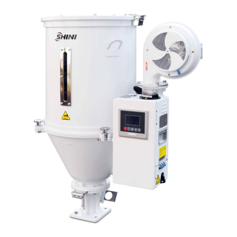
Shini MHD U Series User manual

Smart Modular
Dehumidifying Dryer
Date:Dec.2016
Version:Ver.A(English)


3(55)
Contents
1. General Description..................................................................................... 7
1.1 CodingPrinciple......................................................................................8
1.2 Feature....................................................................................................9
1.3 Machine Specifications......................................................................... 10
1.3.1 Outline Drawing........................................................................... 10
1.3.2 Specification List.......................................................................... 11
1.4 SafetyRegulations................................................................................ 14
1.4.1 SafetySignsand Labels.............................................................. 14
1.4.2 Signsand Labels......................................................................... 15
1.4.3 Transportation andStorageoftheMachine................................. 15
1.4.4 SafetyRegulationsforthe Blowers.............................................. 16
1.5 ExemptionClause................................................................................. 18
2. StructureCharacteristics and WorkingPrinciple.................................... 19
2.1 RelativeHumidityand Dew-point.......................................................... 19
2.2 WorkingPrinciple.................................................................................. 19
2.3 AccessoryOption.................................................................................. 20
2.3.1 MaterialSuction Box.................................................................... 20
2.3.2 Dew-point Monitor....................................................................... 20
3. Installation and Debugging........................................................................ 22
3.1 Machine Installation.............................................................................. 22
3.2 PowerConnectors................................................................................. 23
3.3 Application ............................................................................................ 24
4. Operation..................................................................................................... 25
4.1 Steps..................................................................................................... 25
4.2 PanelDescription.................................................................................. 26
4.2.1 InitialMenu .................................................................................. 26
4.2.2 Password..................................................................................... 26
4.2.3 Dehumidifyingprocess menu...................................................... 27
4.2.4 Dryingprocess menu................................................................... 28
4.2.5 ParameterMenu.......................................................................... 32
4(55)
4.2.6 TendencyChart........................................................................... 38
4.2.7 Alarm ........................................................................................... 39
4.3 ControlPanel........................................................................................ 41
4.4 PanelOperation.................................................................................... 41
4.5 TemperatureSetting............................................................................. 41
4.6 Lock Setup ............................................................................................ 41
4.7 PIDSetting............................................................................................ 42
4.8 Communication Setting......................................................................... 43
4.9 WrongCodesRemark........................................................................... 45
5. Trouble-shooting ........................................................................................ 46
6. Maintenance and Repair............................................................................ 47
6.1 Honeycomb-rotor.................................................................................. 49
6.1.1 Whatis honeycomb-rotor”?........................................................ 49
6.1.2 Installation of the Rotor(SD-120H~700H-SM) ............................ 49
6.2 EGO...................................................................................................... 52
6.3 Filter...................................................................................................... 52
6.4 Cooler................................................................................................... 52
6.5 Operationand Debuggingof Air-doorActuator..................................... 53
6.6 MaintenanceSchedule.......................................................................... 54
6.6.1 Machine Information.................................................................... 54
6.6.2 Check AfterInstallation................................................................ 54
6.6.3 DailyChecking............................................................................. 54
6.6.4 WeeklyChecking......................................................................... 54
6.6.5 MonthlyChecking........................................................................ 55
6.6.6 Half-yearlyChecking ................................................................... 55
6.6.7 YearlyChecking .......................................................................... 55
6.6.8 3yearChecking........................................................................... 55
TableIndex
Table1-1: SpecificationListofMHD-U............................................................. 11
Table1-2: SpecificationListofSD-H-SM......................................................... 11
Table1-3: CombinationsofMHD-U andSD-H-SM.......................................... 12

5(55)
Table1-4: DryingCapacity............................................................................... 12
Table4-2: AdjustmentofProportion(P)........................................................... 36
Table4-3: AdjustmentofIntegralTime(I)........................................................ 36
Table4-4: AdjustmentofDifferentTime(I)....................................................... 36
Table4-5: SystemSlarmInformation ............................................................... 40
Pictureindex
Picture1-1: Outline Drawing............................................................................. 10
Picture2-1:WorkingPrincipleIllustration ......................................................... 19
Picture2-2: MaterialSuction Box...................................................................... 20
Picture3-1: Installation Diagram....................................................................... 22
Picture3-2:WiringDiagram.............................................................................. 23
Picture3-3: Smart ModularDehumidifierInstallation Diagarm ......................... 24
Picture4-1: SystemOperationDiagram........................................................... 25
Picture6-1: HoneycombRotor......................................................................... 49
Picture6-2: Honeycomb-rotorInstallation1...................................................... 49
Picture6-3: Honeycomb-rotorInstallation2...................................................... 50
Picture6-4: Honeycomb-rotorInstallation3...................................................... 50
Picture6-5: Honeycomb-rotorInstallation4...................................................... 50
Picture6-6: EGO .............................................................................................. 52
Picture6-7: FilterCleanig................................................................................. 52
Picture6-8: Air-doorActuator........................................................................... 53

6(55)

7(55)
1. General Description
Pleasereadthroughthisoperation manualbeforeusingthemachine to
prevent damagesofthemachineorpersonalinjuries.
Smartmodulardehumidifyingdryeradoptsmodularstructure,detachablefloor
standforinstantmovementandinstallation.Itcan collocatewithonedehumifierto
severalhopperdryersinprocessing.It mainlyused todehumidifyone orseveral
typesofhighhygroscopicengineeringplastics withhighefficiency.
Model: Smartmodulardehumidifyingdryer

8(55)
1.1CodingPrinciple
SSMD-U iscomposedbyMHD-Uand SD-H-SM.
Notes:
P=Forpolishedhopperinside
Notes*
SM4=Max. optionalwith4MHD-U
SM8=Max. optionalwith8MHD-U
SM12=Max. optionalwith12 MHD-U

9(55)
1.2Feature
lWithautodetectingandadjustmentofair flow, it can saveenergy.
lWithinverterblowercontrol, it cantimelyofferrequired air flowtorealize
rationaluseofenergy.
lSpecialair flowprocessingmanagement can realizehighefficientdrying
operation.
lAdopt PLCandHMI controlsystemforcentralmonitorand operation.
lModularized assemblywayisconvenientforinstallationofmodularhopper
dryer.
lIt’sofsimpleoperationmanagementsystem.
All serviceworkshouldbe carried outbyapersonwithtechnicaltrainingor
correspondingprofessionalexperience.Themanualcontainsinstructionsforboth
handlingand servicing.Chapter6,whichcontainsserviceinstructionsintended for
serviceengineers. Otherchapterscontaininstructionsforthedailyoperator.
Anymodificationsofthe machinemustbeapprovedbySHINIinordertoavoid
personalinjuryanddamagetomachine.Weshall notbe liableforanydamage
causedbyunauthorized changeof themachine.
Ourcompanyprovidesexcellentafter-salesservice.Shouldyou haveany
problemduringusingthemachine,pleasecontactthecompanyorthe local
vendor.
Headquarterand Taipeifactory
Tel:(886)226809119
ShiniPlastics Technologies(Dongguan), Inc
Tel:(86)769 81116600
ShiniPlastics TechnologiesIndiaPvt.Ltd.
Tel:(91)250 3021166

10(55)
1.3MachineSpecifications
1.3.1Outline Drawing
MHD-UMHD-U-M
SD-H-SM
Picture1-1: Outline Drawing

11(55)
1.3.2Specification List
Table1-1: SpecificationListofMHD-U
Model
Insulated
Hopper
Capacity
L)
Drying
Heater
(kW)
Dimension
HxWxD)
Discharge
PortHeight
(mm)H1
AirInlet
PipeDia.
(inch)
AirOutlet
PipeDia.
(inch)
Weight
(kg)
MHD-20U(-M) 20 2.2 1253x550x801 605 2 1.5 40
MHD-40U(-M) 40 3.0 1348x550x801 570 2 1.5 70
MHD-80U(-M) 80 3.9 1865x632x860 520 2 2 85
MHD-120U(-M)
120 3.9 1795x632x860 535 2.5 2.5 90
MHD-160U(-M)
160 6 2180x632x860 535 2.5 2.5 105
MHD-230U(-M)
230 6 2175x732x1000
630 3 3 120
MHD-300U(-M)
300 12 2510x732x1000
630 3 3 130
MHD-450U(-M)
450 12 2414x853x1120
575 3 2.5 160
MHD-600U(-M)
600 18 3036x853x1120
645 4 3 200
Power: 3Φ,400VAC,50Wereservetherighttochange
specificationswithoutpriornotice.
Table1-2: SpecificationListofSD-H-SM
ModelSD-120H-SM SD-200H-SM SD-400H-SM SD-700H-SM
Regen.Heater(kW) 3 4 7.2 10
Regen.Blower (kW) 0.4 0.4 0.75 1.5
Process Blower(kW) 0.75 1.5 3.75 7.5
DryAirCapacity(m3/hr) 120 200 400 700
PipeDia.(inch) 2 2.5 3 4
CoolingWaterQuantity
(L/min) 15 30 50 80
Dimensions
H(mm) 1360 1560 1745 1935
W(mm) 530 660 700 900
D(mm) 820 1050 1255 1380
Weight(kg) 170 265 330 480
Note 1)Dew-point monitorforrandomcheck,plus D”at modelbehind.Wereservetherighttochange
2)Power 3Ф,400VAC,50Hz.specifications withoutprior notice.

12(55)
Table1-3: CombinationsofMHD-U andSD-H-SM
Model
Process
Air
Flow
(m /hr)
Max.
Hopper
Capacity
(L)
Dimension
(H ×W ×D)
MHD
-20U
MHD
-40U
MHD
-80U
MHD
-120U
MHD
-160U
MHD
-230U
MHD
-300U
MHD
-450U
MHD
-600U
SD
-120H-SM* 120 230 1360 ×530 ×
820 √√
SD
-200H-SM**
200 450 1560 ×660
×1050 √√√
SD
-400H-SM**
400 750 1745 ×700
×1255 √√
SD
-700H-SM**
700 1200 1935 ×900 ×
1380 √√
Notes: 1) The combinationway shouldbe based onthe configurationtable. Combinationsof one-to-one”are optional.Inaddition,thetotal capacity of
allmachinesshouldnotbelarger thanthe largest capacity oftheassembly. If thereisanyother configuration requirement, please ask for
specialmake.
2) "* "stands for the collocationwithSM8, SM4. "** "stands for it only canwork with SM4. The instructionof collocationis onlyfor the models in
the Table. If there're other requirements for theconfiguration, the customizationis available.
3) SD-H+MHD-U also could refer to abovecollocation.
Table1-4: DryingCapacity
Material
Drying
Temp.
Drying
Time(hr)
Specific
Heat
(J/kg.)
Bulk
Density
(kg/dm3)
Moisture
Content
before
Drying(%)
Moisture
Content
before
Drying(%)
Drying capacity(kg/hr)
SD-120H
-SM
SD-200H
-SM
SD-400H
-SM
SD-700H
-SM
ABS 80 2-3 0.34 0.6 0.3 0.02 35 105 210 355
CA 75 2-3 0.5 0.5 1 0.02 30 90 180 295
CAB 75 2-3 0.5 0.5 0.8 0.02 30 90 180 295
CP 75 2-3 0.6 0.6 1 0.02 35 106 210 355
LCP 150 4 0.6 0.6 0.04 0.02 27 80 160 265
POM 100 2 0.35 0.6 0.2 0.02 53 160 320 530
PMMA 80 3 0.35 0.65 0.5 0.02 38 115 230 383
IONOME
R
90 3-4 0.55 0.5 0.1 0.04 22 66 133 220
PA
6/6.6/6.10
75 4-6 0.4 0.65 1 0.05 19 58 115 192
PA11 75 4-5 0.58 0.65 1 0.05 23 69 138 230
PA12 75 4-5 0.28 0.65 1 0.05 23 69 138 230
PC 120 2-3 0.28 0.7 0.3 0.01 41 124 250 413
PU 90 2-3 0.45 0.65 0.3 0.02 38 115 230 383
PBT 130 3-4 0.3-0.5
0.7 0.2 0.02 31 93 186 310
PE 90 1 0.55 0.6 0.01 <0.01 106 318 637 1062
PEI 150 3-4 0.6 0.6 0.25 0.02 27 80 160 265
PET 160 4-6 0.3-0.5
0.85 0.2 0.02 25 75 150 250
PETG 70 3-4 0.6 0.6 0.5 0.02 27 80 160 265

13(55)
PEN 170 5 0.85 0.85 0.1 0.05 30 90 180 300
PES 150 4 0.7 0.7 0.8 0.02 30 90 180 300
PMMA 80 3 0.65 0.65 0.5 0.02 28 115 230 385
PPO 110 1-2 0.4 0.5 0.1 0.04 44 133 265 440
PPS 150 3-4 0.6 0.6 0.1 0.02 27 80 160 265
PI 120 2 0.27 0.6 0.4 0.02 53 160 320 530
PP 90 1 0.46 0.5 0.1 0.02 88 265 530 885
PS(GP) 80 1 0.28 0.5 0.1 0.02 88 265 531 885
PSU 120 3-4 0.31 0.65 0.3 0.02 29 85 173 290
PVC 70 1-2 0.2 0.5 0.1 0.02 44 135 265 442
SAN(AS)
80 1-2 0.32 0.5 0.1 0.05 44 135 265 442
TPE 110 3 0.7 0.7 0.1 0.02 40 125 250 413
Notes:1)Useseparateddryinghopper.
2) Moisturecontentlower than0.005%afterdryingwhen in 20℃ambienttemperatureand65%relativehumidity.
3) Specific modelselection,pleaseconsultwithShinimembers.

14(55)
1.4SafetyRegulations
Note!
Electricalinstallationofthe machine shouldbedonebyqualified
electricians.
Beforeconnectthrough powersupply,makesurethatpowerswitchspecifications
andsecurityratingsaresuitableandreliable,andalsothemainswitchisturnedto
OFF.Turnoffmainswitchand auto-startswitchbeforeserviceand maintenance.
1.4.1SafetySignsand Labels
Danger!
Highvoltagedanger!
Thislabelisstuck onthe electricalboxes.
Attention!
Thislabelmeansthatthisarea shouldbetaken care!
Warning!
Hightemperature, takecareof hands!
Thislabelshouldbestick tothe shell of heater.
Attention!
Noneed forregularinspectionbecauseall theelectricalpartsinthecontrol
unit arefixed tightly!
Note!
Noneed of adjustmentofEGO becausethe defaulthasbeen set !
Attention!
Thehot-air pipeline must be well connectedbeforemachine start!

15(55)
1.4.2Signsand Labels
Pushswitchofshut-offplate:
I: Pull O:Push
Wateroutlet: drainageoutlet.
Waterinlet:inletforreplenishingwater
and coolingwater.
1.4.3Transportation andStorageoftheMachine
Transportation
1)SSMD-U seriessmartmodulardryersareseparatelypacked inSD-H-SM
and MHD-U bycratesorplywood caseswithwooden pallet at thebottom,
suitableforquick positioningbyforklift.
2)Afterunpacked, castorsequipped onthemachine canbeused foreaseof
movement.
3)Donotrotatethe machine and avoidcollision withotherobjectsduring
transportationtoprevent improperfunctioning.
4)Thestructureof themachineiswell-balanced, althoughitshouldalsobe
handled withcarewhenliftingthemachineforfearoffallingdown.
5)Themachineand itsattachedpartscanbekept atatemperaturefrom
-25 to+55 forlong distancetransportation andforashortdistance,it
can betransported withtemperatureunder+70 .
Storage
1)SSMD-U seriessmartmodulardryershouldbestoredindoorswith
temperaturekeptfrom5 to40 and humiditybelow80%.
2)Disconnectall powersupplyand turnoffmainswitchand controlswitch.
3)Keepthewholemachine,especiallythe electricalcomponentsawayfrom
watertoavoidpotentialtroublescaused bythe water.
4)Plasticfilmshouldbeused toprotect the machine fromdustandrains.

16(55)
Workingenvironment
Indoorsinadryenvironmentwithmax.temperature+45 andhumidityno more
than80%.
Donotusethemachine
1)If it iswithadamaged cord.
2)Onawetfloororwhenit isexposedtoraintoavoidelectricalshock.
3)If ithasbeendroppedordamageduntil it ischeckedorfixed byaqualified
serviceman.
4)Thisequipment works normallyinthe environment withaltitudewithin
3000m.
5)At leastaclearanceof1msurroundingtheequipment isrequiredduring
operation.Keep thisequipment awayfromflammablesourcesat least two
meters.
6)Avoidvibration, magneticdisturbanceat the operationarea.
Rejectedpartsdisposal
When theequipmenthasrunoutitslifetimeandcannotbeused anymore,
unplugthepowersupplyand disposeof it properlyaccordingtolocalcode.
Firehazard
Incaseoffire, CO2drypowderfireextinguishershouldbe applied.
1.4.4SafetyRegulationsforthe Blowers
1)Undernormaloperation, theblowerswill generatehightemperature. Do
not touchblower's casetoavoidanyphysicalinjury.
2)Undernormaloperation,theblowermotor's currentloadingwill increaseor
reduceaccordingtoairpressure's changeaccordingly.Whileinstallation,
an adequatemotoroverload protection switchshouldbeinstalled withfull
loadingtest, toensureoperatingsafelyunderfull-loadingtoavoidmotor's
damage.
3)Toavoidanyblock materials,dust, powder,fiberparticlesandwaterdrops
enteringtheblower, andhencecausethedeficiencyof itsperformance.

17(55)
Thismachine iswell designed withair filters,sopleaseclean up thefilter
withanyforeignparticles(recommended toclean up thisfilterweekly).
4)Clean the blowersbothinternalandexternalparts(especiallyforthefan
coolingpath), and removesurfacedust if necessary. If moredustsare
accumulated, itwill causedeficiencyforventilation,temperaturerising,
vacuumpowerreduced, vibration increasedand soit will causemachine
brokedown.
5)Ball bearing, oil sealand soundproof arebelongingtoconsumableparts
and soithasalifeperiod and requiresregularreplacement. Meanwhile,
blade,externalcase,and metallicscreenetc.shouldbereplacedregularly
forbestperformance.
6)Undernormaloperation, ifthe blowersarenot runningsmoothlyor
abnormalnoiseappeared. Pleaseimmediatelyshut downthemachine for
repair.
Picture1-2: Blower

18(55)
1.5ExemptionClause
Thefollowingstatementsclarifythe responsibilitiesand regulationsbornbyany
buyeroruserwho purchasesproductsandaccessoriesfromShini(including
employeesandagents).
Shiniisexempted fromliabilityforanycosts,fees,claimsandlossescausedby
reasonsbelow:
1)Anycareless orman-madeinstallations, operation and maintenances
uponmachineswithoutreferringtotheManualpriortomachine using.
2)Anyincidentsbeyondhuman reasonablecontrols, whichinclude
man-made viciousordeliberatedamagesorabnormalpower, and
machine faultscaused byirresistiblenaturaldisastersincludingfire,flood,
stormandearthquake.
3)Anyoperationalactionsthatarenotauthorized byShiniuponmachine,
includingaddingorreplacingaccessories,dismantling, deliveringor
repairing.
4)Employingconsumablesoroil mediathatarenotappointed byShini.

19(55)
2. Structure Characteristics andWorkingPrinciple
2.1RelativeHumidityandDew-point
Relativehumidity:Relativeair humiditymeansrealvaporcontenttosaturated
vaporat thesametemperatureinpercentage.
Dewpoint: itmeansthattemperaturewhenthe saturation vaporbeginstodew.
When therelativehumidityis100%,theambienttemperatureisthedewpoint
temperature.Themorelowerofdewpointtemperature(than theambient
temperature)is,themoreless possibletodew,thatalsomeansthe moredrierthe
air is.Thedewpointwill notbeinfluencedbytemperature,butinfluencedby
pressure.
2.2WorkingPrinciple
Picture2-1:WorkingPrincipleIllustration
Afterdry-hotair fromdryinghoppergetsthroughreturn-air filter,itentersthe
coolerforcoolingthenblewintothe honeycombrotor.Themoistureinambientair
wasabsorbed byrotor,then absorbed byregenerativeheatingair.The two
streamsofair worked on therotoratthesametimeandrotatewiththe rotor,which
makesthe moistureinambientair constantlyabsorbedand exhaustedby
regenerativeair, therefore, itformsthe lowdew-point air. Air-speed sensorat inlet
ofeachdryinghoppercan detectthe actualdryingair flowinthe pipe,andthe
hopperrequired dryingair can be autoadjusted byair-flowautoregulator.By

20(55)
heatingtoplasticdryingtemperature,theairwasblownintothe dryinghopper
whichformsthehermeticcirculation todrythematerials.
2.3AccessoryOption
2.3.1MaterialSuction Box
Europeanstyleinappearancedesign,workwithdryerthathasafloorstandand
vacuumloader, suitableformaterialsunction and discharging.
MHD-20U-120U MHD-160Uand above
Picture2-2: MaterialSuctionBox
Table2-1: SpecificationsofMaterialSuctionBox
Applied to
ModelMHD-20U~120U MHD-160U and above
SBU -20-38S -160-38S
SBU -20-50S -160-50S
SBU -20-38D -160-38D
SBU -20-50D -160-50D
Notes 1)Installpneumaticshut off valve(add ”V”at the endof modelcode).
2) Changeintostainless steel material (add S”at the end ofmodelcode).
3) Stainless steel polishing (add P”at the end of themodelcode).
4) S”standsforsingletubesuctionboxand D”standsfor doubletubessuctionbox.
2.3.2Dew-point Monitor
1. Installedonthe machine
Picture2-26: Dew-point MonitorInstalledonThe Machine
This manual suits for next models
23
Table of contents
Other Shini Dryer manuals

Shini
Shini SDL-U-HD Series User manual

Shini
Shini CD SERIES User manual

Shini
Shini CD SERIES User manual

Shini
Shini SHD Series User manual

Shini
Shini SHD U-HD Series User manual

Shini
Shini SHD-EB User manual

Shini
Shini SHD-E User manual

Shini
Shini SCD Series User manual

Shini
Shini CD SERIES User manual

Shini
Shini SHD Series User manual