SHUR-DRI SD-520C-T7-01 User manual
SD-520C-T7-01
SHUR-DRI PUMP COMPANY | 293 WRIGHT STREET | DELAVAN, WI 53115 SD872 (8/27/09)
INSTALLATION MANUAL
CONVERTIBLE JET PUMP/TANK SYSTEM
Pages 2–14
MANUEL D’INSTALLATION
SYSTÈME DE POMPE À ÉJECTEUR CONVERTIBLE
ET À RÉSERVOIR
Pages 15-27
MANUAL DE INSTALACIÓN
SISTEMA DE TANQUE/BOMBA DE CHORRO
CONVERTIBLE
Paginas 28-40
CONSUMER HOT-LINE: 1-800-535-4950
Monday-Friday 7:30 AM to 5 PM CST

Safety 2
READ AND FOLLOW
SAFETY INSTRUCTIONS!
This is the safety alert symbol. When you see this
symbol on your pump or in this manual, look for
one of the following signal words and be alert to the
potential for personal injury:
warns about hazards that will cause serious
personal injury, death or major property damage if
ignored.
warns about hazards that can cause serious
personal injury, death or major property damage if
ignored.
warns about hazards that will or can cause
minor personal injury or property damage if ignored.
The label NOTICE indicates special instructions which
are important but not related to hazards.
Carefully read and follow all safety instructions in this
manual and on pump.
Keep safety labels in good condition.
Replace missing or damaged safety labels.
ELECTRICAL SAFETY
Capacitor voltage may be hazardous. To
discharge motor capacitor, hold insulated handle screw-
driver BY THE HANDLE and short capacitor terminals
together. Do not touch metal screwdriver blade or
capacitor terminals. If in doubt, consult a qualified elec-
trician.
GENERAL SAFETY
Do not touch an operating motor. Modern
motors are designed to operate at high temperatures. To
avoid burns when servicing pump, allow it to cool for 20
minutes after shut-down before handling.
Do not allow pump or any system component to freeze.
To do so will void warranty.
Pump water only with this pump.
Periodically inspect pump and system components.
Wear safety glasses at all times when working on pumps.
Keep work area clean, uncluttered and properly lighted;
store properly all unused tools and equipment.
Keep visitors at a safe distance from the work areas.
Pump body may explode if used as a
booster pump unless relief valve capable of passing full
pump flow at 75 psi is installed.
WARNING
Hazardous pressure!
Install pressure relief
valve in discharge pipe.
Release all pressure on
system before working on
any component.
WARNING
Hazardous voltage.
Can shock, burn, or
cause death.
Ground pump before
connecting to power
supply. Disconnect power
before working on pump,
motor or tank.
Wire motor for correct
voltage. See “Electrical”
section of this manual and
motor nameplate.
Ground motor before
connecting to power
supply.
Meet National Electri-
cal Code, Canadian
Electrical Code, and local
codes for all wiring.
Follow wiring instruc-
tions in this manual
when connecting motor to
power lines.
For parts or assistance, call SHUR-DRI Customer Service at 1-800-535-4950

Table of Contents 3
Thank you for purchasing a top quality, factory tested pump.
Page
General Safety .....................................................................................................2
Performance.........................................................................................................3
Replacing An Existing Pump ................................................................................4
New Shallow Well Installation.............................................................................5
New Deep Well Installation.................................................................................6
• 4-inch or larger well casing (A “Double Pipe” Well)
• 2-inch well casing (A “Single Pipe” Well)
Electrical..........................................................................................................7, 8
Preparing To Start The Pump – Deep Well...........................................................9
Preparing To Start The Pump – Shallow Well ....................................................10
Troubleshooting..................................................................................................11
Repair Parts ................................................................................................12, 13
Warranty............................................................................................................14
7
6
5
4
3
2
1
0
3020 40 50 60 70
PUMPING DEPTH IN FEET
ER
US
S
ER
P
I
S
P
03T
A
ET
UNIMR
E
P
SN
O
L
L
A
G
DEEP WELL PUMP CAPACITIES
5971 0309
11
10
9
8
7
6
5
4
3
2
1
0
0 5 10 15 20
PUMPING DEPTH IN FEET
ER
USSE
RPISP
0
3
T
A
E
T
UNI
M
REP
SN
O
L
L
A
G
SHALLOW WELL PUMP CAPACITIES
5972 0309
PERFORMANCE
For parts or assistance, call SHUR-DRI Customer Service at 1-800-535-4950
Replacing an Existing Pump 4
DEEP WELL
Hazardous voltage. Disconnect power to pump before working
on pump or motor.
Step 1. Drain and remove the old pump. Check pipe for scale, lime, rust,
etc., and replace it if necessary.
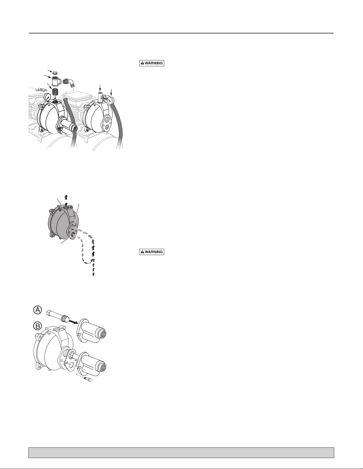
Step 2. Install the pressure regulator and pressure gauge in the pump body
(see Figure 1).
NOTICE: Your old ejector (in the well) may not be properly
matched to your new pump. If the pump does not perform
properly, we recommend that you install ejector kit R-E520-100-01,
included with the pump.
Step 3. Install the pump and tank in the system. Make sure that all pipe
joints in the suction pipe are air-tight as well as water tight. If the
suction pipe can suck air, the pump will not be able to pull water
from the well.
Step 4. Adjust the pump mounting height so that the plumbing connections
do not put a strain on the pump body. Support the pipe so that the
pump body does not take the weight of piping or fittings.
Step 5. Run piping from the discharge tee in the tank flange to the household
piping. The discharge piping must be at least as large as the tank tee.
Install a relief valve in the discharge pipe capable of passing the entire
pump flow at 75 psi. Run a pipe from the relief valve to a floor drain
or some other convenient place to carry off the water.
You have just completed the well plumbing for your new deep well jet
pump/tank system. Please go to Page 7 for electrical connections.
SHALLOW WELL
Hazardous voltage. Disconnect power to pump before working
on pump or motor.
Step 1. Drain and remove the old pump. Check the old pipe for scale, lime,
rust, etc., and replace it if necessary.
Step 2. Remove the pressure regulator from the pump body. Replace it with
a 1” NPT close nipple, a 1”x1”x3/4” NPT Tee, and a 1” NPT pipe
plug (see Figure 1). Install the pressure gage in the plugged hole in
the pump body (see Figure 1).
Step 3. Install the ejector kit. Follow the instructions provided with the kit.
Be sure to align the venturi with the top hole on the front of the
pump (see Figure 3).
NOTICE: Always replace the ejector when replacing the pump in a
shallow well installation.
Step 4. Install the pump and tank in the system. Make sure that all pipe
joints in the suction pipe are air-tight as well as water tight. If the
suction pipe can suck air, the pump will not be able to pull water
from the well.
Step 5. Adjust the pump mounting height so that the plumbing connections
do not put a strain on the pump body. Support the pipe so that the
pump body does not take the weight of piping or fittings.
Step 6. Run piping from the discharge tee in the tank flange to the household
piping. The discharge piping must be at least as large as the tank tee.
Install a relief valve in the discharge pipe capable of passing the entire
pump flow at 75 psi. Run a pipe from the relief valve to a floor drain
or some other convenient place to carry off the water.
You have just completed the well plumbing for your new shallow well jet
pump/tank system. Please go to Page 7 for electrical connections.
5985 0409
ShallowWell Deep Well
1” Tee*
1” Pipe Plug*
1” Nipple* Pressure
RegulatorGage
* Purchase Separately
Gage
Replace Regulator
with:
Drive
(Smaller)
Port
Suction
(Larger)
Port
Piping and Pressure
Regulator omitted
for clarity
Discharge
Drive Pipe
sends water
down the well
to drive water
up through the
Suction Pipe
to Pump Suction
5980 0309
Figure1: Install Pressure Regulator
and Gauge for deep well. Install
Priming Tee and Gauge for
shallow well.
Figure 2: Drive and Suction Functions
Figure 3: Mount Ejector – Shallow Well
For parts or assistance, call SHUR-DRI Customer Service at 1-800-535-4950

New Shallow Well Installation 5
ALL SHALLOW WELL INSTALLATIONS
Step 1. Remove the control valve from the pump body. Replace it with a 1”
NPT close nipple, a 1”x1”x3/4” NPT Tee, and a 1” NPT pipe plug
(see Figure 1). Install the pressure gage in the plugged hole in the
pump body (see Figure 1).
Step 2. Install the ejector kit. Follow the instructions provided with the kit.
Align the venturi with the top hole on the front of the pump (see
Figure 3).
CASED WELL INSTALLATION, 2" OR LARGER
CASING (Figure 4)
Step 3. Mount the pump as close to the well as possible. Connect the pipe
from the well to the pump suction port, using the fewest possible
fittings – especially elbows – as fittings increase friction in the pipe.
Step 4. Assemble the foot valve, strainer, and well pipe (see Figure 4).
Make sure that the foot valve works freely.
Step 5. Lower the pipe into the well until the strainer is five feet above the
bottom of the well. It should also be at least 10 feet below the
well’s water level while the pump is running in order to prevent the
pump from sucking air. Install a sanitary well seal.
DRIVEN POINT INSTALLATION (Figure 5)
Step 3. Drive the well, using “drive couplings” and a “drive cap”. “Drive
fittings” are threaded all the way through and allow the pipe ends
to butt against each other so that the driving force of the maul is
carried by the pipe and not by the threads. The ordinary fittings
found in hardware stores are not threaded all the way through the
fitting and can collapse under impact. “Drive fittings” are also
smoother than standard plumbing fittings, making ground penetra-
tion easier.
Step 4. Mount the pump as close to the well as possible.
Step 5. If one well point does not supply enough water, consider connect-
ing two or three well points to one suction pipe.
ALL SHALLOW WELL INSTALLATIONS
Step 6. Install a priming tee, priming plug, and suction pipe to the pump
(see Figures 4 and 5). Connect the pipe from the well to the pump
suction port, using the fewest possible fittings – especially elbows –
as fittings increase friction in the pipe.
• The suction pipe should be at least as large as the suction port on
the pump (include a check valve – see Figures 4 and 5).
• Support the pipe so that there are no dips or sags in the pipe, so it
doesn’t strain the pump body, and so that it slopes slightly
upward from the well to the pump (high spots can cause air
pockets which can air lock the pump).
• Seal the suction pipe joints with teflon tape or pipe joint com-
pound approved for use on PVC. Joints must be air- and water-
tight. If the suction pipe can suck air, the pump cannot pull water
from the well.
Step 7. Run piping from the discharge tee in the tank flange to the house-
hold piping. The discharge piping must be at least as large as the tank
tee. Install a relief valve in the discharge pipe capable of passing the
entire pump flow at 75 psi. Run a pipe from the relief valve to a floor
drain or some other convenient place to carry off the water.
You have just completed the piping for your new shallow well jet
pump/tank system. Please go to Page 7 for electrical connections.
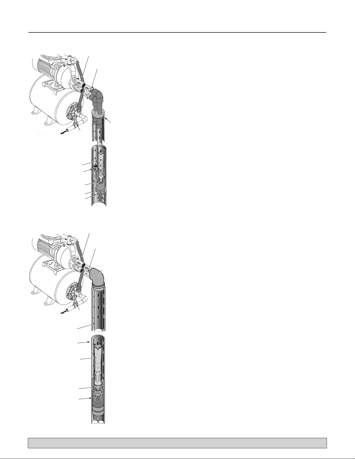
5988 0409
To Household
Water System
Suction Pipe
From Well
Replace Pressure
Regulator with
Priming Tee
(see fig. 1)
Priming
Tee and
Plug
Not
to
Scale
Relief Valve
Drive
Coupling
Drive
Point
Check
Valve
Figure 5: Driven Point Installation
5974 0309
To Household
Water System
Suction Pipe
From Well
Priming
Tee and
Plug
Not
to
Scale
Well
Casing
Foot
Valve
Sanitary
Well Seal
Strainer
5-10'
At least
10'
Relief Valve
Replace Pressure
Regulator with
Priming Tee
(see fig. 1)
5974 0309
To Household
Water System
Suction Pipe
From Well
Priming
Tee and
Plug
Not
to
Scale
Well
Casing
Foot
Valve
Sanitary
Well Seal
Strainer
5-10'
At least
10'
Relief Valve
Replace Pressure
Regulator with
Priming Tee
(see fig. 1)
Figure 4: Cased Well Installation
For parts or assistance, call SHUR-DRI Customer Service at 1-800-535-4950

Suction (Larger)
Pipe from Well
To Household
Water System
Well
Head
Drive (Smaller)
Pipe to Well
Venturi
Nozzle
Ejector
Not
to
Scale
Foot Valve
Strainer
5975 0309
Relief
Valve
Pressure Regulator,
Gauge, and Priming
Plug
New Deep Well Installation 6
4" OR LARGER WELL (Figure 6)
Step 1. Install the pressure regulator and pressure gauge in the pump body.
See Figure 1, Page 4.
Step 2. Assemble the ejector kit. See Figure 6. Follow the instructions
included with the kit in order to match the nozzle and venturi to
your well conditions.
Step 3. Mount the pump as close to the well as possible.
Step 4. Connect two pipes (1" drive, 1-1/4" suction) to the ejector and
lower the ejector into the well until it is five feet from the bottom. It
should also be at least 10 feet below the well’s water level while
the pump is running in order to prevent the pump from sucking air.
Step 5. Install a sanitary well seal and connect the ejector piping to the
pump. Use steel nipples through the well seal with flexible poly
pipe to avoid crushing the plastic pipe when tightening the seal.
Step 6. Support the pipe so that there are no dips or sags in the pipe, so it
doesn’t strain the pump body, and so that it slopes slightly upward
from the well to the pump (high spots can cause air pockets which
can air lock the pump). Seal the suction pipe joints with teflon tape
or a teflon based pipe joint compound. Joints must be air- and
water-tight. If the suction pipe can suck air, the pump cannot pull
water from the well.
Step 7. Run piping from the discharge tee in the tank flange to the household
piping. The discharge piping must be at least as large as the tank tee.
Install a relief valve in the discharge pipe capable of passing the
entire pump flow at 75 psi. Run a pipe from the relief valve to a floor
drain or some other convenient place to carry off the water.
You have just completed the plumbing for your new double pipe deep
well jet pump. Please go to Page 7 for electrical connections.
2" WELL (Figure 7)
Step 1. Install the pressure regulator and pressure gauge in the pump body.
See Figure 1, Page 4.
Step 2. Mount the pump as close to the well as possible.
Step 3. Assemble ejector kit, well piping, and well head adapter according
to the instructions provided with the ejector package. See Figure 7.
Use galvanized drop pipe with turned couplings to allow proper
flow. Follow the instructions included with the kit in order to match
the nozzle and venturi to your well conditions.
Step 4. Run two pipes (one smaller drive pipe, one larger suction pipe)
from the well to the pump. Support the pipe so that there are no
dips or sags in the pipe, so it doesn’t strain the pump body, and so
that it slopes slightly upward from the well to the pump (high spots
can cause air pockets which can air lock the pump). Seal the suc-
tion pipe joints with teflon tape or a teflon based pipe joint com-
pound. Joints must be air- and water-tight. If the suction pipe can
suck air, the pump cannot pull water from the well.
Step 5. Run piping from the discharge tee in the tank flange to the household
piping. The discharge piping must be at least as large as the tank tee.
Install a relief valve in the discharge pipe capable of passing the
entire pump flow at 75 psi. Run a pipe from the relief valve to a floor
drain or some other convenient place to carry off the water.
You have just completed the plumbing for your new single pipe deep well
jet pump. Please go to Page 7 for electrical connections.
NOTE: The ejector kit supplied with your pump tank system will not work with
a 2” or 3” well. You must purchase separately an ejector for a 2” or 3” well.
Figure 6: 4” and Larger Deep Well
Figure 7: 2” (Single Pipe) Deep Well
Suction (Larger)
Pipe from Well
To Household
Water System
Relief
Valve
Pressure Regulator,
Gauge, and Priming
Plug
41
JET NO. J32P- 24
Well
Head
Drive (Smaller)
Pipe
to
Well
Well Casing
serves as
Drive Pipe
Suction Pipe
Venturi
Nozzle
Ejector
Not
to
Scale
5976 0309
For parts or assistance, call SHUR-DRI Customer Service at 1-800-535-4950

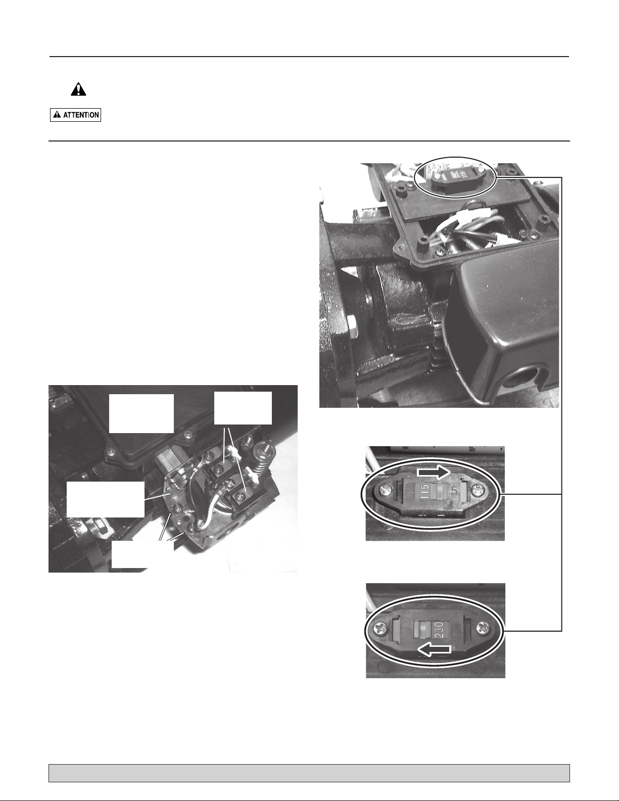
Electrical 7
5982 0409
Figure 9B: Pump is shipped from factory set for
115-volt operation (above).To change to 230-volt
operation, slide switch to display ‘230’ (below).
Figure 9A: Remove cover from capacitor box to
reach voltage change slide switch.
Figure 9C: Slide switch set for 230-volt operation.
CHECK VOLTAGE SETTING.
1. Turn off power to the pump!
2. Determine if the circuit for the pump is 115 or
230 volts.
3. A qualified person must install electrical wiring.
4. The voltage switch is factory set to 115 volts. If you
have 115 volt service, do not change the selection.
1/2 HP motors are preset at the factory for 115 volts.
5. To change the voltage (if necessary), remove the
motor capacitor cover and slide the switch fully to
the correct voltage.
6. Reinstall the cover.
Do Not Turn On Power Yet!
CONNECT POWER SUPPLY WIRING
TO PRESSURE SWITCH
1. Remove the pressure switch cover.
2. Attach power and ground wires to the pressure
switch as indicated.
3. Reinstall the cover.
Do Not Turn On Power Yet!
Motor
Capacitor
Cover
Pressure
Switch
(Cover Removed)
Ground Wire
Connection
Power
Supply
Connections
Figure 8: Connect power supply wires to pressure
switch as shown.
Disconnect power before working on pump, motor, pressure switch, or wiring.
Never wire a 115 volt motor to a 230 volt line.
For parts or assistance, call SHUR-DRI Customer Service at 1-800-535-4950
Electrical 8
Hazardous voltage. Can shock, burn, or kill. Connect ground
wire before connecting power supply wires. Use the wire size (including
the ground wire) specified in the wiring chart. If possible, connect the
pump to a separate branch circuit with no other appliances on it.
Explosion hazard. Do not ground to a gas supply line.
WIRING CONNECTIONS
Fire hazard. Incorrect voltage can cause a fire or seriously
damage the motor and voids the warranty. The supply voltage must be
within ±10% of the motor nameplate voltage.
NOTICE: The motor is factory wired for 115 volts. If necessary, reconnect
the motor for 230 volts, as shown in Figures 9A, 9B, and 9C. Do not
attempt to operate the pump as it comes from the factory on 230 volts.
Install, ground, wire, and maintain your pump in compliance with the
National Electrical Code (NEC) or the Canadian Electrical Code (CEC), as
applicable, and with all local codes and ordinances that apply. Consult
your local building inspector for code information.
Connection Procedure:
Step 1. Connect the ground wire first as shown in Figure 8. The ground
wire must be a solid copper wire at least as large as the power
supply wires.
Step 2. There must be a solid metal connection between the pressure
switch and the motor for motor grounding protection. If the pres-
sure switch is not connected to the motor, connect the green
ground screw in the switch to the green ground screw under the
motor end cover. Use a solid copper wire at least as large as the
power supply wires.
Step 3. Connect the ground wire to a grounded lead in a service panel, to a
metal underground water pipe, to a metal well casing at least ten
feet (3M) long, or to a ground electrode provided by the power
company or the hydro authority.
Step 4. Connect the power supply wires to the pressure switch as shown in
Figure 8.
You have just completed the wiring for your pump.
Please go to Page 9 or 10 for startup preparations.
Nameplate Branch Fuse
DISTANCE IN FEET FROM MOTOR TO SUPPLY
Motor HP Volts Amps Rating Amp 0 - 50 51 - 100 101 - 200 201 - 300 301 - 400 401 - 500
AWG WIRE SIZE (mm2)
1/2 115 7.0 15 14 (2) 14 (2) 12 (3) 10 (5.5) 10 (5.5) 8 (8.4)
1/2 230 3.5 15 14 (2) 14 (2) 14 (2) 14 (2) 14 (2) 14 (2)
Wiring Chart – Recommended Wire and Fuse Sizes
For parts or assistance, call SHUR-DRI Customer Service at 1-800-535-4950
Preparing to Start the Pump – Deep Well 9
Never run pump dry. Running pump without water may cause
pump to overheat, damaging seal and possibly causing burns to persons
handling pump. Fill pump with water before starting.
Never run pump against closed discharge. To do so can boil
water inside pump, causing hazardous pressure in unit, risk of explosion
and possibly scalding persons handling pump.
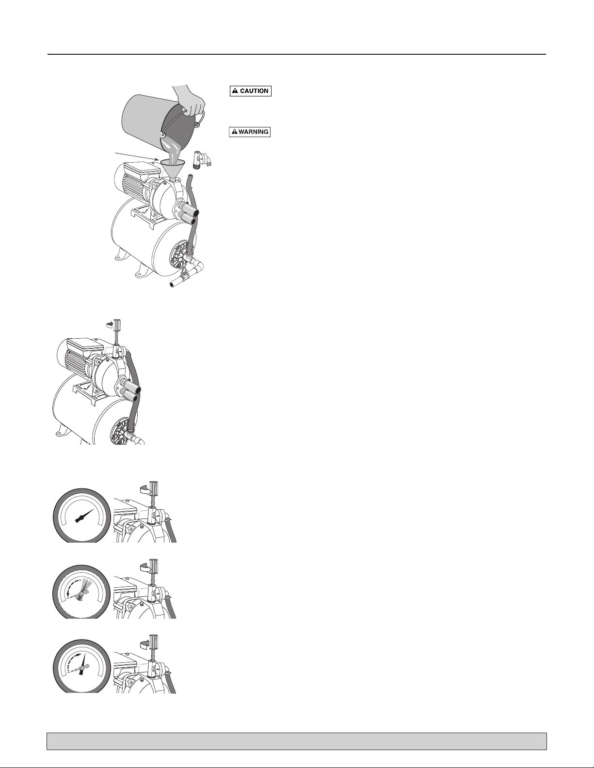
Step 1. Open the pressure regulator as far as possible without backing it
out of the regulator body. Then remove the regulator from the
pump and fill the pump, fill all piping between the pump and the
well, and make sure that all piping in the well is full. If you have
also installed a priming tee in the suction piping, remove the plug
from the tee and fill the suction piping (see Figure 10).
Step 2. Replace all fill plugs and close the control valve completely
(Figure 11).
Step 3. Power on! Start the pump and watch the pressure gauge. The
pressure should build rapidly to about 50 PSI as the pump primes.
Step 4. After 2 or 3 minutes, the gauge should show pressure. If not, stop
the pump, remove the fill plugs, reopen the control valve, and refill
the pump and piping. You may have to repeat this two or three
times in order to get all the trapped air out of the piping. Don’t for-
get to close the control valve each time before you start the pump.
Step 5. When pressure has built up and stabilized at about 50 PSI, slowly
open the control valve (see Figure 12) and let the pressure drop
until the pressure gauge needle starts to flutter or drops to 0. When
the needle flutters or drops, close the valve just enough to stop the
flutter or bring the needle back to a stable pressure (see Figure 12).
Your pump is now operating at its most efficient point.
Step 6. After the pump has built up pressure in the system and shut off,
check the pressure switch operation by opening a faucet or two and
running enough water out to bleed off pressure until the pump
starts. The pump should start when pressure drops to 30 PSI and
stop when pressure reaches 50 PSI. Run the pump through one or
two complete cycles to verify correct operation. This will also help
clean the system of dirt and scale dislodged during installation.
Congratulations on a successful installation.
If you were unsuccessful, please refer to the Troubleshooting section
(Page 11) or call our customer service technical staff.
Remove pressure
regulator and fill
pump and
suction piping
through pump
discharge port.
5977 0309
Figure 11: Prime Pump
Figure 12: Set Control Valve
A-SLOWLY open Pressure Regulator
B-Watch for Gauge to Flutter or Drop
C-Close Pressure Regulator until Pressure
Stabilizes 5979 0309
Figure 10: Fill Pump
Replace pressure
regulator and all fill
plugs, reconnect the
hose, and close
the regulator
completely
5978 0309
For parts or assistance, call SHUR-DRI Customer Service at 1-800-535-4950

Preparing to Start the Pump – Shallow Well 10
Never run pump dry. Running pump without water may cause
pump to overheat, damaging seal and possibly causing burns to persons
handling pump. Fill pump with water before starting.
Never run pump against closed discharge. To do so can boil
water inside pump, causing hazardous pressure in unit, risk of explosion
and possibly scalding persons handling pump.
Step 1. Remove the priming plug from the pump and fill the pump, fill all
piping between the pump and the well, and make sure that all pip-
ing in the well is full (see Figure 13). If you have also installed a
priming tee in the suction piping, remove the plug from the tee and
fill the suction piping.
Step 2. Replace all fill plugs.
Step 3. Power on! Start the pump. The pump should pump water in two or
three minutes.
Step 4. If you don’t have water after 2 or 3 minutes, stop the pump and
remove the fill plugs. Refill the pump and piping. You may have to
repeat this two or three times in order to get all the trapped air out
of the piping.
Step 5. After the pump has built up pressure in the system and shut off,
check the pressure switch operation by opening a faucet or two and
running enough water out to bleed off pressure until the pump
starts. The pump should start when pressure drops to 30 PSI and
stop when pressure reaches 50 PSI. Run the pump through one or
two complete cycles to verify correct operation. This will also help
clean the system of dirt and scale dislodged during installation.
Congratulations on a successful installation.
If you were unsuccessful, please refer to the Troubleshooting section
(Page 11) or call our customer service technical staff.
Remove fill
plug and fill pump
and suction piping
through priming tee.
Figure 13: Fill Pump through
Priming Tee
For parts or assistance, call SHUR-DRI Customer Service at 1-800-535-4950

Troubleshooting 11
* (Note:
Stop pump;
then check prime
before looking for
other causes.
Unscrew
priming
plug and see if water
is in priming hole).
SYMPTOM POSSIBLE CAUSE(S) CORRECTIVE ACTION
Motor will not run Disconnect switch is off Be sure switch is on.
Fuse is blown or circuit breaker tripped Replace fuse or reset circuit breaker.
Starting switch is defective DISCONNECT POWER; Replace starting switch.
Wires at motor are loose, Refer to instructions on wiring (Pages 7 and 8). DISCONNECT POWER;
disconnected, or wired incorrectly check and tighten all wiring.
Capacitor voltage may be hazardous. To discharge
capacitor, hold insulated handle screwdriver BY THE HANDLE and
short capacitor terminals together. Do not touch metal screwdriver
blade or capacitor terminals. If in doubt, consult a qualified electrician.
Pressure switch contacts are dirty DISCONNECT POWER and file contacts with emery board or nail file.
Motor runs hot and Motor is wired incorrectly Refer to instructions on wiring.
overload kicks off Voltage is too low Check with power company. Install heavier wiring if wire size is too small
(See Electrical / Wiring Chart).
Pump cycles too frequently See section below on too frequent cycling.
Motor runs but no Pump in new installation did In new installation:
water is delivered* not pick up prime through:
1. Improper priming 1. Re-prime according to instructions.
2. Air leaks 2. Check all connections on suction line, AVC, and ejector with
soapy water or shaving cream.
3. Leaking foot valve or check valve 3. Replace foot valve or check valve.
Pump has lost prime through: In installation already in use:
1. Air leaks 1. Check all connections on suction line and shaft seal.
2. Water level below suction pipe inlet 2. Lower suction line into water and re-prime. If receding water level
in well exceeds 20’ (6.1M), a deep well pump is needed.
Foot valve or strainer is plugged Clean foot valve or strainer.
Ejector or impeller is plugged Clean ejector or impeller.
Check valve or foot valve is stuck shut Replace check valve or foot valve.
Pipes are frozen Thaw pipes. Bury pipes below frost line. Heat pit or pump house.
Foot valve and/or strainer are Raise foot valve and/or strainer above bottom of water source.
buried in sand or mud Clean foot valve and strainer.
Water level is too low for shallow A deep well jet will be needed if your well is more than 20’ (6.1M)
well setup to deliver water depth to water.
Pump does not Water level in well is lower than A new nozzle and venturi combination may be needed.
deliver water to full estimated
capacity Steel piping (if used) is corroded or Replace with plastic pipe where possible, otherwise with new steel pipe.
(Also check point limed, causing excess friction
3 immediately above) Piping is too small in size Use larger piping.
Pump delivers water but
Pressure switch is out of adjustment or DISCONNECT POWER; adjust or replace pressure switch.
does not shut off or contacts are welded together
pump cycles too Faucets have been left open Close faucets.
frequently Venturi, nozzle or impeller is clogged Clean venturi, nozzle or impeller.
Standard pressure tank is waterlogged Drain tank to air volume control port. Check AVC for defects. Check
and has no air cushion all connections for air leaks.
Pipes leak Check connections.
Foot valves leak Replace foot valve.
Pressure switch is out of adjustment Adjust or replace pressure switch.
Air charge too low in pre-charged tank DISCONNECT POWER and open faucets until all pressure is relieved.
Using tire pressure gauge, check air pressure in tank at valve stem
located on the tank. If less than pressure switch cut-in setting (30-50
PSI), pump air into tank from outside source until air pressure is 2 PSI
less than cut-in setting of switch. Check air valve for leaks (use soapy
solution) and replace core if necessary.
Air spurts from faucets Pump is picking up prime When pump has picked up prime, it should pump solid water with no air.
Leak in suction side of pump Suction pipe is sucking air. Check joints for leaks with soapy water.
Well is gaseous Consult factory about installing a sleeve in the well.
Intermittent over-pumping of well. Lower foot valve if possible, otherwise restrict pump discharge.
(Water drawn down below foot valve.)
For parts or assistance, call SHUR-DRI Customer Service at 1-800-535-4950
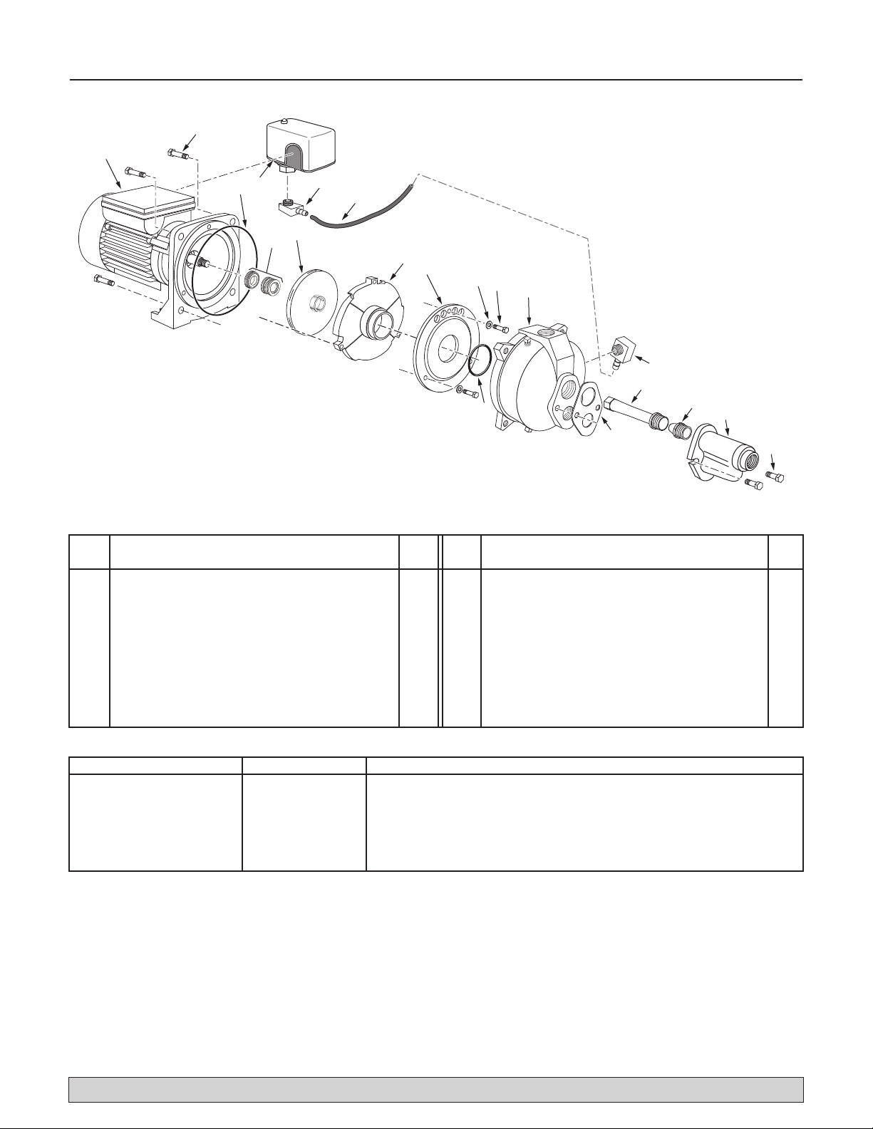
Key Part
No. Description Qty.
1 Motor/Seal Plate Assembly 1
1A Motor Flange Screw 4
2 Seal Plate O-Ring 1
3 Pressure Switch 1
4 Shaft Seal 1
5 Impeller 1
6 1/4” NPT x 1/4” Barb Elbow 2
7 Hose 1
8 Diffuser 1
9 Diffuser Plate 1
Key Part
No. Description Qty.
9A Diffuser Plate O-Ring 1
10 Diffuser Plate Washer 3
11 Diffuser Plate Screw 3
12 Pump Body 1
13 Venturi 1
14 Nozzle 1
15 Ejector Body 1
16 Ejector Capscrew 2
17 Ejector Gasket 1
1
23
5
4
6
1A
7
8
9
9A
6
17
13
14 15
16
12
10 11
5983 0409
Repair Parts 12
** Kit covers more than one pump. These parts are not used with this pump.
For parts or assistance, call SHUR-DRI Customer Service at 1-800-535-4950
Kit Description Kit Number Kits Include (Quantity included in kit if more than 1):
Seal and O-Ring Kit: RPK-35 Key Nos. 2, 4, 9A, 13, 17
Overhaul Kit RPK-205DW Key Nos. 1A, 2, 4, 5, 8, 9, 9A , 10(3), 11(3), 13**, 14**, Venturi O-Ring**
Ejector Kit FP520-100 Key Nos. 6(2), 7, 13(5), 14(2), 15, 16(2), 17, Venturi O-Ring**
Pump Body Assembly R176-72 Key Nos. 2, 6, 9A, 12, 17, 1/4” NPT Plug(2), 1/2” NPT Plug
Pressure Switch TC2151 Key No. 3
Pressure Switch Tubing Kit FPASFK Key Nos. 6(2), 7

Repair Parts 13
1
2
3
4
4
6
7
8
9
10
11
5
5984 0409
For parts or assistance, call SHUR-DRI Customer Service at 1-800-535-4950
Key Part Part
No. Description Qty. Number
1 Pressure Regulator 1 FPAPR
2 Pressure Gauge 1 TC2104
3 3/4” NPT x 1” Hose Barb 90° Elbow 1 U78-770P
4 1” Hose Clamp 2 U19-55SS
5 1” x 15” Hose 1 U74-37R
6 3/4” NPT x 1” Hose Barb Adapter 1 24206A004
7 3/4” NPT x 3/4” NPT x 3/4” NPT Street Tee 1 05002A001
8 5/16”-18 Flanged Nuts 6 U36-202BT
9 Tank Flange 1 U31-442P
• Tank Bladder 1 U20-7
10 Tank Body 1*
11 Air Valve with Cap 1 U212-160
* If tank body fails, replace entire tank (Part Number RT6H).
• Not illustrated.

Warranty 14
For parts or assistance, call SHUR-DRI Customer Service at 1-800-535-4950
RETAIN ORIGINAL RECEIPT FOR YOUR RECORDS.
LIMITED WARRANTY
SHUR-DRI warrants to the original consumer purchaser (“Purchaser” or “You”) of its products that they are free from
defects in material and workmanship for a period of twelve (12) months from the date of the original consumer purchase.
If, within twelve (12) months from the original consumer purchase, any such product shall prove to be defective, it shall be
repaired or replaced at SHUR-DRI’s option, subject to the terms and conditions set forth below. The original purchase
receipt and product warranty information label are required to determine warranty eligibility. Eligibility is based on purchase
date of original product – not the date of replacement under warranty. The warranty is limited to repair or replacement of
product only – Purchaser pays all removal, installation, labor, shipping, and incidental charges.
For parts or troubleshooting assistance, DO NOT return product to your retail store. Contact SHUR-DRI Customer Service
at 1-800-535-4950.
Claims made under this warranty shall be made by returning the product (except sewage pumps, see below) to the retail
outlet where it was purchased immediately after the discovery of any alleged defect. SHUR-DRI will subsequently take
corrective action as promptly as reasonably possible. No requests for service will be accepted if received more than
30 days after the warranty expires.
Warranty does not apply to products used in commercial/rental applications.
SEWAGE PUMPS
DO NOT return a sewage pump (that has been installed) to your retail store. Contact SHUR-DRI Customer Service.
Sewage pumps that have seen service and been removed carry a contamination hazard with them.
If your sewage pump has failed:
•Wear rubber gloves when handling the pump;
• For warranty purposes, return the pump’s cord tag and original receipt of purchase to the retail store;
• Dispose of the pump according to local disposal ordinances.
Exceptions to the Twelve (12) Month Limited Warranty
Product Warranty Period
Models SD106, SD107 90 Days
Models SDAS3, SDVS3, SDSU25, SD-CUST 2 Years
Model SDAS5 3 Years
Pre-Charge Water System Tank 5 Years
Sewage Pump (Model SDLTW50),
Submersible Sump Pump (Models SDLT50 and SDLT75) Lifetime
General Terms and Conditions
You must pay all labor and shipping charges necessary to replace product covered by this warranty. This warranty does
not apply to the following: (1) acts of God; (2) products which, in SHUR-DRI’s sole judgement, have been subject to
negligence, abuse, accident, misapplication, tampering, or alteration; (3) failures due to improper installation, operation,
maintenance or storage; (4) atypical or unapproved application, use or service; (5) failures caused by corrosion, rust or
other foreign materials in the system, or operation at pressures in excess of recommended maximums.
This warranty sets forth SHUR-DRI’s sole obligation and purchaser’s exclusive remedy for defective products.
SHUR-DRI SHALL NOT BE LIABLE FOR ANY CONSEQUENTIAL, INCIDENTAL, OR CONTINGENT DAMAGES
WHATSOEVER.
THE FOREGOING WARRANTIES ARE EXCLUSIVE AND INLIEU OF ALL OTHER EXPRESS AND IMPLIED
WARRANTIES, INCLUDING BUT NOT LIMITED TO THE IMPLIED WARRANTIES OF MERCHANTABILITY AND
FITNESS FOR A PARTICULAR PURPOSE. THE FOREGOING WARRANTIES SHALL NOT EXTEND BEYOND THE
DURATIONPROVIDED HEREIN.
Some states do not allow the exclusion or limitation of incidental or consequential damages or limitations on how long an
implied warranty lasts, so the above limitations or exclusions may not apply to You. This warranty gives You specific legal
rights and You may also have other rights which vary from state to state.
SHUR-DRI PUMP COMPANY • 293 Wright St. • Delavan, WI U.S.A. 53115
Phone: 1-800-535-4950
Web Site: http://www.shur-dri.com

Sécurité 15
LIRE TOUTES CES INSTRUCTIONS
ET LES SUIVRE!
Ce symbole indique qu'il faut être prudent.
Lorsque ce symbole apparaît sur la pompe ou dans
cette Notice, rechercher une des mises en garde qui
suivent, car elles indiquent un potentiel possible de
blessures corporelles :
avertit d'un danger qui causera des
blessures corporelles, la mort ou des dommages
matériels importants si on l'ignore.
avertit d'un danger qui risque de causer
des blessures corporelles, la mort ou des dommages
matériels importants si on l'ignore.
avertit d'un danger qui causera ou qui
risquera de causer des blessures corporelles, la mort ou
des dommages matériels importants si on l'ignore.
Le mot NOTA indique des instructions spéciales et
importantes n'ayant aucun rapport avec les dangers.
Lire attentivement toutes les consignes de sécurité
contenues dans cette Notice ou collées sur la pompe.
Garder les autocollants de sécurité en bon état; les
remplacer s'ils manquent ou s'ils ont été endommagés.
SÉCURITÉ CONCERNANT
L'ÉLECTRICITÉ
La tension du condensateur peut être
dangereuse. Pour décharger le condensateur du moteur,
tenir un tournevis à manche isolé PAR LE MANCHE et
mettre en court-circuit les bornes du condensateur. Ne
pas toucher la lame métallique du tournevis ni les bornes
du condensateur. En cas de doute, consulter un élec-
tricien qualifié.
SÉCURITÉ GÉNÉRALE
Ne pas toucher un moteur qui fonctionne.
Les moteurs modernes sont conçus pour fonctionner par
des températures élevées. Pour ne pas se brûler lorsque
l'on interviendra sur la pompe, la laisser refroidir pen-
dant 20 minutes après l'avoir arrêtée avant de la toucher.
Ne pas laisser geler la pompe ni aucun autre élément du
système, sinon la garantie sera annulée.
Ne pomper que de l'eau avec cette pompe.
Périodiquement, inspecter la pompe et tous les éléments
du système.
Toujours porter des lunettes de sécurité lorsque l'on
intervient sur une pompe.
Garder la zone de travail propre, non encombrée et bien
éclairée; tous les outils et tout l'équipement non utilisés
doivent être entreposés correctement.
Ne pas laisser les visiteurs s'approcher de la zone de
travail.
Le corps de la pompe peut exploser si la
pompe est utilisée en tant que pompe de surpression, à
moins qu'une soupape de sûreté pouvant laisser passer
le débit maximum de la pompe à 75 lb/po2soit posée.
AVERTISSEMENT
Pression dangereuse!
Poser une soupape de sûreté
sur le tuyau de refoulement.
Dissiper toute la pression
du système avant d'intervenir
sur un élément.
AVERTISSEMENT
Tension dangereuse. Risque
de secousses électriques, de
brûlures, voire de mort.
Mettre à la terre la pompe
avant de la brancher sur le
courant électrique. Couper
l'arrivée de courant avant d'in-
tervenir sur la pompe, sur le
moteur ou sur le réservoir.
Câbler le moteur en
fonction de la bonne
tension. Voir la Section
«Électricité» de cette Notice
et la plaque signalétique du
moteur.
Mettre à la terre le
moteur avant de le
brancher sur le courant
électrique.
Conforme au Code
national de l'électric-
ité, au Code canadien de
l'électricité et aux codes
municipaux pour tous les
câblages.
Respecter les instructions de câblage figurant dans
cette Notice lorsque l'on branche le moteur sur
une ligne haute tension.
Pour obtenir des pièces ou de l’aide, appeler le Service à la clientèle SHUR-DRI en composant le 1 800 535-4950
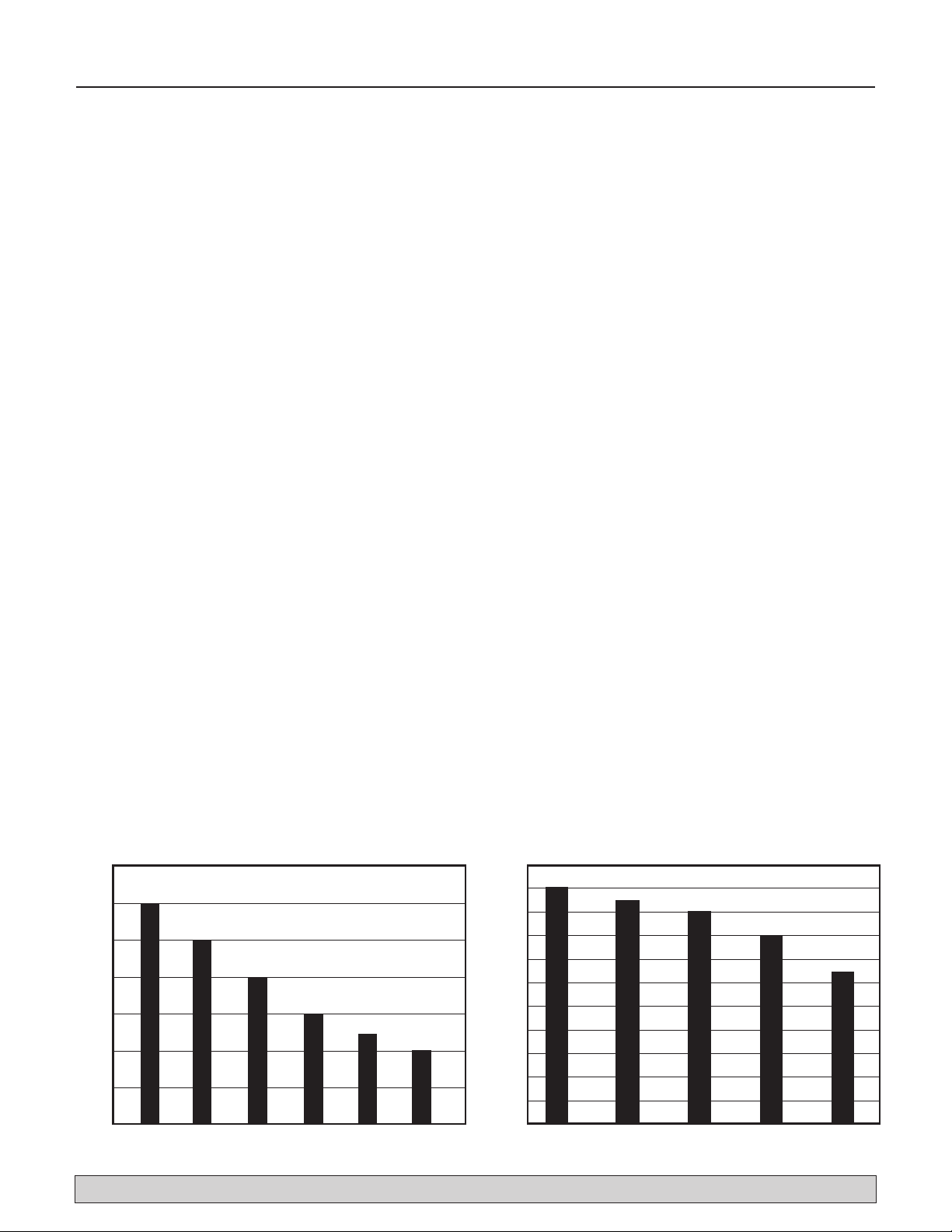
Table des matières 16
Merci d'avoir acheté une pompe de qualité supérieure mise à l'essai à l'usine.
Page
Sécurité ..........................................................................................................................15
Rendement .....................................................................................................................16
Remplacement d'une pompe existante ...........................................................................17
Installation sur un nouveau puits peu profond................................................................18
Installation sur un nouveau puits profond.......................................................................19
• Puits de 4 pouces de diamètre ou plus grand (puits à «deux tuyaux»)
• Puits de 2 pouces (puits à «un seul tuyau»)
Électricité .................................................................................................................20, 21
Préparations avant le démarrage de la pompe - Puits profond........................................22
Préparations avant le démarrage de la pompe - Puits peu profond.................................23
Diagnostic des pannes....................................................................................................24
Pièces de rechange...................................................................................................25, 26
Garantie .........................................................................................................................27
7
6
5
4
3
2
1
0
3020 40 50 60 70
PUMPING DEPTH IN FEET
ER
US
S
ER
P
I
S
P
03T
A
ET
UNIMR
E
P
SN
O
L
L
A
G
DEEP WELL PUMP CAPACITIES
5971 0309
11
10
9
8
7
6
5
4
3
2
1
0
0 5 10 15 20
PUMPING DEPTH IN FEET
ER
USSE
RPISP
0
3
T
A
E
T
UNI
M
REP
SN
O
L
L
A
G
SHALLOW WELL PUMP CAPACITIES
5972 0309
RENDEMENT
DÉBITS DES POMPES POUR PUITS PROFOND
GALLONS PAR MINUTE À 30 LB/PO2
PROFONDEUR DE POMPAGE EN PIEDS
DÉBITS DES POMPES POUR PUITS PEU PROFOND
GALLONS PAR MINUTE À 30 LB/PO2
PROFONDEUR DE POMPAGE EN PIEDS
Pour obtenir des pièces ou de l’aide, appeler le Service à la clientèle SHUR-DRI en composant le 1 800 535-4950

Remplacement d'une pompe existante 17
PUITS PROFONDS
Tension dangereuse. Couper l'arrivée de courant à la pompe
avant d'intervenir sur la pompe ou sur le moteur.
1 ° Vider toute l'eau de l'ancienne pompe; déposer l'ancienne pompe. Vérifier
la tuyauterie à la recherche de dépôts de tartre, de chaux, de rouille, etc.;
la remplacer selon le besoin.
2 ° Poser le régulateur de pression et le manomètre sur le corps de la pompe
(voir la Figure 1).
NOTA : L’ancien éjecteur (celui qui est dans le puits) ne s’assortira peut-
être pas bien avec la nouvelle pompe. Si le rendement de la nouvelle
pompe n’est pas adéquat, nous recommandons de poser un nécessaire
d’éjecteur R-E520-100-01 (fourni).
3 ° Raccorder la pompe et le réservoir au réseau d’alimentation. S'assurer que
tous les raccords du tuyau d'aspiration sont bien étanches, aussi bien à l'air
qu'à l'eau. Si le tuyau d'aspiration aspire de l'air, la pompe ne pompera
pas l'eau du puits.
4 ° Régler la hauteur de montage de la pompe de façon que les raccords de
plomberie n'exercent aucune contrainte sur le corps de la pompe.
Supporter les tuyaux de façon que le corps de la pompe ne supporte pas le
poids de la tuyauterie ni des raccords.
5 ° Raccorder une extrémité de la tuyauterie au té de refoulement de la bride
du réservoir et l’autre à la tuyauterie de la maison. Le diamètre de la tuyau-
terie de refoulement doit être égal ou supérieur à celui du té du réservoir.
Poser une soupape de sûreté sur le tuyau de refoulement pour que
l’écoulement de la pompe soit de 75 lb/po2. Faire passer un tuyau de la
soupape de sûreté jusqu’à un avaloir de sol ou tout autre dispositif qui
permet de faire évacuer l’eau.
Le raccordement de la pompe à éjecteur pour puits profond neuve et du réser-
voir est maintenant terminé. Voir à la page 20 pour les connexions électriques.
PUITS PEU PROFONDS
Tension dangereuse. Couper l'arrivée de courant à la pompe
avant d'intervenir sur la pompe ou sur le moteur.
1 ° Vider toute l'eau de l'ancienne pompe; déposer l'ancienne pompe. Vérifier
la tuyauterie à la recherche de dépôts de tartre, de chaux, de rouille, etc.;
la remplacer selon le besoin.
2 ° Retirer le régulateur de pression du corps de la pompe et la remplacer par
un mamelon simple, un té de 1 po x 1 po x 3/4 po à filetage NPT et un
bouchon de 1 po à filetage NPT (voir la figure 1). Poser le manomètre dans
le trou de visite du corps de la pompe (voir la figure 1).
3 ° Poser le nécessaire d’éjecteur. Suivre les instructions fournies avec le
nécessaire. S'assurer de bien aligner le venturi avec le trou supérieur qui se
trouve à l'avant de la pompe (voir la Figure 3).
NOTA : Toujours remplacer l'éjecteur lorsque l'on remplace la pompe d'un
puits peu profonds.
4 ° Raccorder la pompe et le réservoir au réseau d’alimentation. S'assurer que
tous les raccords du tuyau d'aspiration sont bien étanches, aussi bien à l'air
qu'à l'eau. Si le tuyau d'aspiration aspire de l'air, la pompe ne pompera
pas l'eau du puits.
5 ° Régler la hauteur de montage de la pompe de façon que les raccords de
plomberie n'exercent aucune contrainte sur le corps de la pompe.
Supporter les tuyaux de façon que le corps de la pompe ne supporte pas le
poids de la tuyauterie ni des raccords.
6 ° Raccorder une extrémité de la tuyauterie au té de refoulement de la bride
du réservoir et l’autre à la tuyauterie de la maison. Le diamètre de la tuyau-
terie de refoulement doit être égal ou supérieur à celui du té du réservoir.
Poser une soupape de sûreté sur le tuyau de refoulement pour que
l’écoulement de la pompe soit de 75 lb/po2. Faire passer un tuyau de la
soupape de sûreté jusqu’à un avaloir de sol ou tout autre dispositif qui
permet de faire évacuer l’eau.
Le raccordement de la pompe à éjecteur pour puits peu profond neuve et
du réservoir est maintenant terminé. Voir à la page 20 pour les connexions
électriques.
Figure 3 : Montage de l'éjecteur - puits
peu profonds
Drive
(Smaller)
Port
Suction
(Larger)
Port
Piping and Pressure
Regulator omitted
for clarity
Discharge
Drive Pipe
sends water
down the well
to drive water
up through the
Suction Pipe
to Pump Suction
5980 0309
Figure 2 : Fonctions d'eau motrice et
d'aspiration
5985 0409
ShallowWell Deep Well
1” Tee*
1” Pipe Plug*
1” Nipple* Pressure
RegulatorGage
* Purchase Separately
Gage
Replace Regulator
with:
Figure 1 : Poser le régulateur de pres-
sion et le manomètre (puits profond).
Poser le té d’amorçage et le
manomètre (puits peu profond).
RefoulementAspiration
(Le plus
grosorifice)
Orifice d'eaumotrice
(Le plus petit) Tuyaud'eau
motrice
Renvoie
l'eaudans le
puitsoù elle est
refoulée
dans le
tuyaud'aspira-
tion, puis
aspirée
parla pompe
PuitspeuprofondPuitsprofond
Remplacerle régulateur
à l’aide d’un :
bouchonfileté de 1 po*
té de 1 po*
mamelon
de 1 po*
Manomètre
Régulateur
de pression
Manomètre
*Piècesvenduesséparément
La tuyauterie et le
régulateur de pressionsont
omisà desfins de clarté
Pour obtenir des pièces ou de l’aide, appeler le Service à la clientèle SHUR-DRI en composant le 1 800 535-4950

Installation sur un nouveau puits peu profond 18
TOUS LES TYPES D’INSTALLATION POUR PUITS
PEU PROFOND
1 ° Retirer la vanne de régulation du corps de la pompe et la remplacer par
un mamelon simple, un té de 1 po x 1 po x 3/4 po à filetage NPT et un
bouchon de 1 po à filetage NPT (voir la figure 1). Poser le manomètre dans
le trou de visite du corps de la pompe (voir la figure 1).
2 ° Poser le nécessaire d’éjecteur. Suivre les instructions fournies avec le
nécessaire. Aligner le venturi avec le trou supérieur qui se trouve à l’avant
de la pompe (voir la figure 3).
INSTALLATION DANS UN PUITS TUBÉ,
TUBAGE DE 2 PO OU PLUS (figure 4)
3 ° Monter la pompe aussi près que possible du puits. Raccorder le tuyau
provenant du puits à l’orifice d’aspiration de la pompe en utilisant le
moins de raccords possible, en particulier des coudes. Les raccords ont
pour effet d’accroître la friction dans le tuyau.
4 ° Poser le clapet de pied, la crépine et le tubage (voir la figure 4). S’assurer
que le clapet de pied fonctionne librement.
5 ° Faire descendre le tuyau dans le puits jusqu’à ce que la crépine se trouve à
5 pi du fond. La crépine doit également se trouver à 10 pi sous la surface
de l’eau lorsque la pompe est en fonction pour éviter qu’elle n’aspire de
l’air. Poser un dispositif d’étanchéité de puits.
INSTALLATION D’UNE POINTE FILTRANTE (figure 5)
3 ° Foncer le puits à l’aide des accouplements d’enfoncement et du couvercle
de tuyau d’enfoncement. Les raccords d’enfoncement sont filetés sur toute
leur longueur afin que les tuyaux puissent être mis bout à bout. Les chocs
de fonçage sont ainsi encaissés par le tuyau et non par les filets. Les
raccords ordinaires vendus dans les quincailleries ne sont pas filetés sur
toute leur longueur et peuvent se briser sous la force d’un impact. Les
raccords d’enfoncement sont également plus souples que les raccords de
plomberie ordinaires, ce qui facilite le fonçage.
4 ° Monter la pompe aussi près que possible du puits.
5 ° Une ou deux pointes filtrantes supplémentaires peuvent devoir être
raccordées au tuyau d’aspiration si le débit d’eau est insuffisant.
TOUS LES TYPES D’INSTALLATION POUR PUITS
PEU PROFOND
6 ° Poser un té d’amorçage, un bouchon d’amorçage et un tuyau d’aspiration
sur la pompe (voir figures 4 et 5). Raccorder le tuyau provenant du puits
à l’orifice d’aspiration de la pompe en utilisant le moins de raccords
possible, en particulier des coudes. Les raccords ont pour effet d’accroître
la friction dans le tuyau.
• Le diamètre du tuyau d’aspiration doit être égal ou supérieur à celui de
l’orifice d’aspiration de la pompe (installer un clapet de non-retour –
voir les figures 4 et 5).
• Le tuyau doit être soutenu de façon à ce qu’il ne soit pas courbé,
n’exerce aucune contrainte sur le corps de la pompe et incliné
légèrement vers le haut du puits à la pompe (les points hauts peuvent
occasionner la formation de poches d’air et obturer le tuyau).
• Étanchéiser les joints du tuyau d’aspiration au moyen de ruban de téflon
ou de pâte à joints pour PVC. Les joints doivent être étanches à l’air et à
l’eau. L’eau du puits ne sera pas pompée si le tuyau d’aspiration aspire
de l’air.
7 ° Raccorder une extrémité de la tuyauterie au té de refoulement de la bride
du réservoir et l’autre à la tuyauterie de la maison. Le diamètre de la
tuyauterie de refoulement doit être égal ou supérieur à celui du té du
réservoir. Poser une soupape de sûreté sur le tuyau de refoulement pour
que l’écoulement de la pompe soit de 75 lb/po2. Faire passer un tuyau de
la soupape de sûreté jusqu’à un avaloir de sol ou tout autre dispositif qui
permet de faire évacuer l’eau.
Le raccordement de la pompe à éjecteur pour puits peu profond neuve et
du réservoir est maintenant terminé. Voir à la page 20 pour les connexions
électriques.
Figure 4 : Installation dans un puits à
tubage
5988 0409
To Household
Water System
Suction Pipe
From Well
Replace Pressure
Regulator with
Priming Tee
(see fig. 1)
Priming
Tee and
Plug
Not
to
Scale
Relief Valve
Drive
Coupling
Drive
Point
Check
Valve
Figure 5 : Installation d’une
pointe filtrante
5974 0309
To Household
Water System
Suction Pipe
From Well
Priming
Tee and
Plug
Not
to
Scale
Well
Casing
Foot
Valve
Sanitary
Well Seal
Strainer
5-10'
At least
10'
Relief Valve
Replace Pressure
Regulator with
Priming Tee
(see fig. 1)
5974 0309
To Household
Water System
Suction Pipe
From Well
Priming
Tee and
Plug
Not
to
Scale
Well
Casing
Foot
Valve
Sanitary
Well Seal
Strainer
5-10'
At least
10'
Relief Valve
Replace Pressure
Regulator with
Priming Tee
(see fig. 1)
Soupape de sûreté
Tuyaud'aspiration
venant dupuits
Té d'amorçage
et bouchon
Joint sanitaire
dupuits
Clapet
de pied
Crépine
5 à 10 pi
Aumoins
10 pi
Pas à
l'échelle
Vers le système d'eau
de la maison
Tubage de puits
Tuyaud'aspiration
venant dupuits
Té d'amorçage
et bouchon
Soupape de sûreté
Pas à
l'échelle
Vers le système d'eau
de la maison
Remplacerle régulateur de
pressionparun té
d’amorçage (voirla figure 1)
Remplacerle régulateur de
pressionparun té
d’amorçage (voirla figure 1)
Clapet de
non-retour
Raccord
d’enfoncement de
la pointe filtrante
Pointe filtrante
Pour obtenir des pièces ou de l’aide, appeler le Service à la clientèle SHUR-DRI en composant le 1 800 535-4950
Installation sur un nouveau puits profond 19
PUITS DE 4 POUCES DE DIAMÈTRE OU PLUS
GRAND (Figure 6)
1 ° Poser le régulateur de pression et le manomètre sur le corps de la pompe
(voir la Figure 1, page 17).
2 ° Poser le nécessaire d’éjecteur. Voir la Figure 6. Suivre les instructions
fournies avec le nécessaire de façon à assortir la buse et le venturi en
fonction des conditions du puits.
3 ° Monter la pompe aussi près que possible du puits.
4 ° Brancher deux tuyaux (de 1 pouce pour l'eau motrice, de 1-1/4 pouce
pour l'aspiration) sur l'éjecteur et abaisser l'éjecteur dans le puits jusqu'à
ce qu'il soit à cinq pieds du fond du puits. Pour que la pompe n'aspire pas
d'air, l'éjecteur doit également être à au moins 10 pieds sous le niveau de
l'eau pendant que la pompe fonctionne.
5 ° Poser un joint sanitaire de puits et brancher la tuyauterie de l'éjecteur sur
la pompe. Dans le cas de tuyaux en plastique souples, utiliser des raccords
en acier là où les tuyaux traversent le joint d'étanchéité du puits pour
éviter d'écraser les tuyaux lors du serrage du joint.
6 ° Supporter le tuyau de façon qu'il ne soit pas cintré afin qu'il n'exerce pas
de contraintes sur le corps de la pompe; de plus, il doit être légèrement
incliné vers le haut, du puits jusqu'à la pompe (les points hauts risquent de
causer des poches et des bouchons d'air dans la pompe). Rendre étanches
les raccords du tuyau d'aspiration avec du ruban téflon ou une pâte pour
raccords filetés à base de téflon. Les raccords doivent être étanches à l'air
et à l'eau. Si le tuyau d'aspiration aspire de l'air, la pompe ne pompera pas
l'eau du puits.
7 ° Raccorder une extrémité de la tuyauterie au té de refoulement de la bride
du réservoir et l’autre à la tuyauterie de la maison. Le diamètre de la
tuyauterie de refoulement doit être égal ou supérieur à celui du té du
réservoir. Poser une soupape de sureté sur le tuyau de refoulement pour
que l’écoulement de la pompe soit de 75 lb/po2. Faire passer un tuyau de
la soupape de sûreté jusqu’à un avaloir de sol ou tout autre dispositif qui
permet de faire évacuer l’eau.
Le branchement de cette pompe à éjecteur neuve pour puits profonds à un seul
tuyau est maintenant terminé. Voir à la page 20 pour les connexions électriques.
PUITS DE 2 POUCES (Figure 7)
1 ° Poser le régulateur de pression sur le corps de la pompe (voir la Figure 1,
Page 17).
2 ° Monter la pompe aussi près que possible du puits.
3 ° Poser le nécessaire d’éjecteur. La tuyauterie du puits et l'adaptateur de la
tête du puits conformément aux instructions fournies avec l'éjecteur. Voir la
Figure 7. Utiliser un tuyau de descente galvanisé muni de raccords usinés
pour assurer un débit adéquat. Suivre les instructions fournies avec le
nécessaire de façon à assortir la buse et le venturi aux conditions du puits.
4 ° Poser deux tuyaux (un de petit diamètre pour l'eau motrice, un de plus gros
diamètre pour l'aspiration) entre le puits et la pompe. Supporter le tuyau de
façon qu'il ne soit pas cintré afin qu'il n'exerce pas de contraintes sur le
corps de la pompe; de plus, il doit être légèrement incliné vers le haut, du
puits jusqu'à la pompe (les points hauts risquent de causer des poches et
des bouchons d'air dans la pompe). Rendre étanches les raccords du tuyau
d'aspiration avec du ruban téflon ou une pâte pour raccords filetés à base
de téflon. Les raccords doivent être étanches à l'air et à l'eau. Si le tuyau
d'aspiration aspire de l'air, la pompe ne pompera pas l'eau du puits.
5 ° Raccorder une extrémité de la tuyauterie au té de refoulement de la bride
du réservoir et l’autre à la tuyauterie de la maison. Le diamètre de la
tuyauterie de refoulement doit être égal ou supérieur à celui du té du
réservoir. Poser une soupape de sûreté sur le tuyau de refoulement pour
que l’écoulement de la pompe soit de 75 lb/po2. Faire passer un tuyau de
la soupape de sûreté jusqu’à un avaloir de sol ou tout autre dispositif qui
permet de faire évacuer l’eau.
Le branchement de cette pompe à éjecteur neuve pour puits profonds à un seul
tuyau est maintenant terminé. Voir à la page 20 pour les connexions électriques.
NOTA : Le nécessaire d’éjecteur fourni avec le présent ensemble ne peut être
utilisé pour les puits de 2 po et de 3 po. Faire l’achat d’un éjecteur distinct
pour ces puits.
Figure 6 : Puits profond de 4 pouces et
de plus grand diamètre
Figure 7 : Puits profond de 2 pouces
(à un seul tuyau)
Suction (Larger)
Pipe from Well
To Household
Water System
Well
Head
Drive (Smaller)
Pipe to Well
Venturi
Nozzle
Ejector
Not
to
Scale
Foot Valve
Strainer
5975 0309
Relief
Valve
Pressure Regulator,
Gauge, and Priming
Plug
Suction (Larger)
Pipe from Well
To Household
Water System
Relief
Valve
Pressure Regulator,
Gauge, and Priming
Plug
41
JET NO. J32P- 24
Well
Head
Drive (Smaller)
Pipe
to
Well
Well Casing
serves as
Drive Pipe
Suction Pipe
Venturi
Nozzle
Ejector
Not
to
Scale
5976 0309
Suction (Larger)
Pipe from Well
To Household
Water System
Well
Head
Drive (Smaller)
Pipe to Well
Venturi
Nozzle
Ejector
Not
to
Scale
Foot Valve
Strainer
5975 0309
Relief
Valve
Pressure Regulator,
Gauge, and Priming
Plug
Suction (Larger)
Pipe from Well
To Household
Water System
Relief
Valve
Pressure Regulator,
Gauge, and Priming
Plug
41
JET NO. J32P- 24
Well
Head
Drive (Smaller)
Pipe
to
Well
Well Casing
serves as
Drive Pipe
Suction Pipe
Venturi
Nozzle
Ejector
Not
to
Scale
5976 0309
Soupape
de sûreté
Conduite d'eaumotrice
(plus petite) vers le puits
Vers le système d'eau
de la maison
Venturi
Éjecteur
Buse
Clapet de pied
Crépine
Tête du
puits
Vers le système d'eau
de la maison
Tuyaud'aspiration
Buse
Éjecteur
Le tubage dupuits
sert de tuyau
d'eaumotrice
Soupape
de sûreté
Tête du
puits
Tuyaud'aspiration(plus grand
diamètre) venant dupuits
Conduite d'eaumotrice
(plus petite) vers le puits
Pas à
l'échelle
Pas à
l'échelle
Venturi
Régulateur de pression, manomètre
et bouchond’amorçage
Tuyaud'aspiration(plus grand
diamètre) venant dupuits
Régulateur de pression, manomètre
et bouchond’amorçage
Pour obtenir des pièces ou de l’aide, appeler le Service à la clientèle SHUR-DRI en composant le 1 800 535-4950
Électricité 20
5982 0409
Figure 9B : La tension est réglée à 115 V (comme
ci-dessus) en usine. Pour changer la tension, glisser le
commutateur de façon à ce que le chiffre « 230 »
soit visible (comme ci-dessous).
Figure 9A : Déposer le couvercle du boîtier de
condensateur pour avoir accès au commutateur à
glissière.
Figure 9C :Tension réglée à 230 V.
RÉGLAGE DE LA TENSION.
1.
Coupez le courant alimentant la pompe!
2. Déterminez si la pompe est alimentée par un circuit
de 115 ou de 230 volts.
3. Seule une personne qualifiée doit procéder au
branchement des fils électriques.
4. Le commutateur de tension est réglé à l’usine à 115
volts. Ne pas modifier la sélection lorsqu’en 115
volts. Les moteurs 1/2 CH sont préréglés à l’usine à
115 volts.
5. Pour modifier la tension (le cas échéant), enlevez le
couvercle de condensateur du moteur et glissez le
commutatuer complètement jusqu’à la bonne
tension.
6. Reposez le couvercle.
Ne démarrez pas la pompe à cet instant!
BRANCHEMENT DES FILS ÉLECTRIQUES
AU PRESSOSTAT.
1. Enlevez le couvercle du pressostat.
2. Branchez le courant d’alimentation et les fils de mise
à la terre au pressostat comme indiqué.
3. Reposez le couvercle.
Ne démarrez pas la pompe à cet instant!
Motor
Capacitor
Cover
Pressure
Switch
(Cover Removed)
Ground Wire
Connection
Power
Supply
Connections
Figure 8 : Brancher les câbles d’alimentation sur le
pressostat, tel qu’indiqué.
Débrancher le courant électrique avant d'intervenir sur la pompe, le moteur, le manostat ou le câblage.
Ne jamais relier un moteur de 115 volts à une canalisation de 230 volts.
Couvercle de
condensateur
du moteur
Pressostat
(couvercle enlevé)
Bornes de
branchement
électrique
Borne de fil de
mise à la terre
Pour obtenir des pièces ou de l’aide, appeler le Service à la clientèle SHUR-DRI en composant le 1 800 535-4950
Table of contents
Languages:
Other SHUR-DRI Water Pump manuals


Popular Water Pump manuals by other brands

LINC milton roy
LINC milton roy 84T-10 Series instruction manual

Draper
Draper SWP220A Instructions for use

GORMAN-RUPP
GORMAN-RUPP 88B3-B Installation, operation and maintenance manual

Graco
Graco Husky 1050A Operation

Veneroni
Veneroni AT Manual for use and maintenance

Agilent Technologies
Agilent Technologies PHV K Series Operating and maintenance instructions


