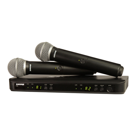
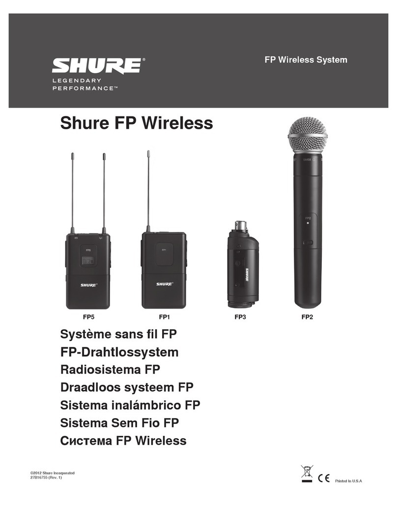
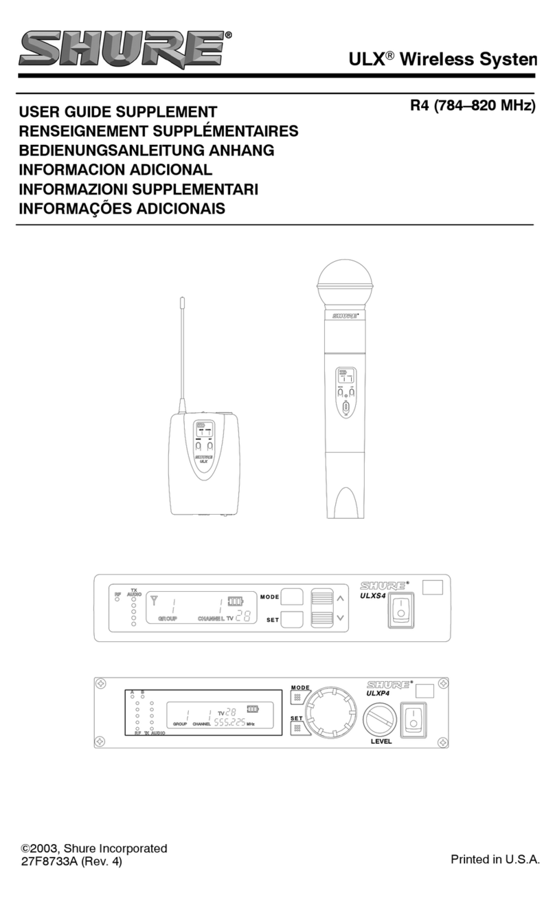
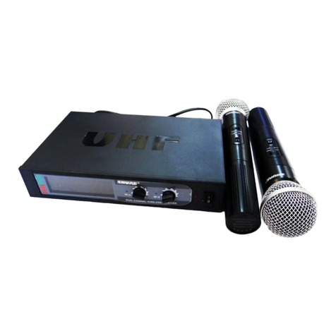
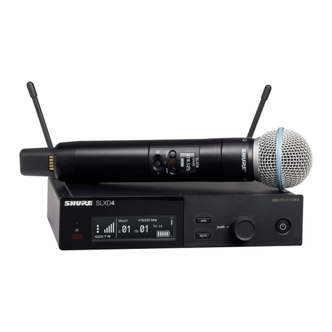
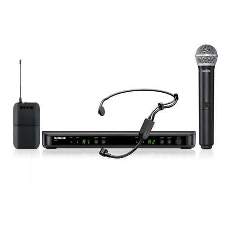
Shure BLX Series User manual

BLX
Wireless Microphone System
Systeme de microphone sans fil
BLX
Sistema de micr6fonos inalambricos
BLX
Sistema de Microfone Sem Fio
BLX
©2014 Shure Incorporated
27A16033 (Rev. 5)
11111111111111111111111111111111111111111111111111
-

IMPORTANT SAFETY INSTRUCTIONS
1.
READ
these instructions.
2.
KEEP
these
instructions.
3.
HEED
all
warnings.
4.
FOLLOW
all
instructions.
5.
DO
NOT
use this apparatus near
water.
6.
CLEAN
ONLY
with
dry
cloth.
7.
DO
NOT
block
any
ventilation openings. Allow sufficient distances for adequate ventila·
lion
and
install
in
accordance
with
the manufacturer's instructions.
8.
DO
NOT install near
any
heat
sources
such
as
open
flames,
radiators, heat registers,
stoves,
or other apparatus (including amplifiers) that produce
heat.
Do
not place
any
open
flame
sources
on
the
product.
9
DO
NOT
defeat the safety purpose
of
the polarized or groundingtype
plug
.A polarized
plug
has
two
blades with
one
wider
than
the other.Agrounding type plug has two blades
and
a third grounding
prong
. The wider blade
or
the third
prong
are provided for your
safety
.
If
the
provided
plug
does
not
fit
into your outlet, consult
an
electrician
for
replace-
ment
of
the
obsolete outlet.
1
0.
PROTECT
the
power
cord
from
being
walked
on
or pinched, particularly
at
plugs, conve·
mence
receptacles,
and
the
point where
they
exit
from
the apparatus.
11.
ONLY
USE
attachments/accessories specified
by
the
manufacturer.
12.
USE
only
with
a
cart,
stand,
tripod, bracket,
or
table
specified
by
the manu· -
facturer, or
sold
with the apparatus.
When
a
cart
is
used,
use
caution
when
moving
the
cart/apparatus combination
to
avoid injury
from
tip-over.
13.
UNPLUG
this
apparatus during lightning storms or
when
unused
for
long
periods of
time.
CONSIGNES DE SECURITE IMPORTANTES
1.
LIRE
ces
consignes.
2.
CONSERVER
ces
consignes.
3.
OBSERVER
taus
les
avertissements.
4.
SUIVRE
toutes les consignes.
5.
NE
PAS
utiliser
cet
appareil
a
proximite de l'eau.
6.
NETIOYER UNIQUEMENT
avec
un
chiffon
sec.
7.
NE
PAS
obstruer
les
ouvertures de ventilation. Laisser
des
distances suffisantes pour
permettre
une
ventilation adequate et effectuer !'installation
en
respectant
les
instructions
du
fabricant.
8.
NE
PAS
installer
a
proximite d'une source de chaleur telle qu'une flamme
nue,
un
radiateur,
une
bouche
de
chaleur,
un
poele
ou
d'autres appareils (dont les amplificateurs)
produisant
de
Ia
chaleur.
Ne
placer aucune source
a
flamme
nue
sur
le
produit.
9.
NE
PAS
deteriorer
Ia
securite
de
Ia
fiche polarise&
ou
de
Ia
fiche
de terre.
Une
fiche
polarise&
comporte deux
lames
dont l'une est plus large que l'autre.
Une
fiche
de
terre
compo.rte
deux lames
et
une
troisieme broche de mise
a
Ia
terre.
La
lame
Ia
plus large
ou
Ia
tro1su~~e
broche assure
Ia
securite de l'utilisateur.
Si
Ia
fiche fournie
ne
s'adapte
pas
a
Ia
pnse electnque, demander
a
un
electrician
de
remplacer
Ia
prise hors
normes.
10.
PROTEGER
le
cordon d'alimentation
afin
que personne
ne
marche dessus et que
rien
ne
le
pince,
en
particulier
au
niveau
des fiches,
des
prises de courant
et
du point de sortie
de l'appareil.
11.
UTILISER UNIQUEMENT les accessoires specifies par
le
fabricant. -
12
.
UTI
USER uniquement
avec
un
chariot,
un
pied,
un
trepied,
un
support
ou
une
table specifie par
le
fabricant
ou
vendu avec l'appareil.
Si
un
chariot
est
utilise,deplacer !'ensemble chariot·appareil avec precaution afin de
ne
pas
le
renverser,
ce
qui pourrait entrainer des blessures.
INSTRUCCIONES IMPORTANTES DE SEGURIDAD
1.
LEA
estas instrucciones.
2.
CONSERVE estas instrucciones.
3.
PRESTE
ATENCION a
todas
las
advertencias.
4.
SIGA
todas las instrucciones.
5.
NO
utilice este aparato cerca del
agua.
6.
LIMPIE
UNICAMENTE
con
un
trapo
seco.
7.
NO
obstruya ninguna de las aberturas
de
ventilaci6n.
Deje
espacio suficiente para
proporcionar ventilaci6n adecuada e instate los equipos
segun
las instrucciones del
fabricante.
8.
NO
instate
el
aparato cerca de fuentes de calor tales como llamas descubiertas, radiad·
ores, registros de calefacci6n, estufas u otros aparatos (incluyendo amplificadores)
que
produzcan calor.
No
coloque artrculos
con
llamas descubiertas
en
el producto.
9.
NO
anule
Ia
funci6n de seguridad del enchufe polarizado o
con
clavija de puesta a tierra.
Un
enchufe polarizado tiene
dos
patas,
una
mas
ancha que
Ia
otra.
Un
enchufe
con
pu·
esta atierra tiene dos
patas
y
una
tercera clavija
con
puesta a tierra.
La
pata
mas
ancha
o
Ia
tercera clavija
se
proporciona para
su
seguridad.
Si
el
tomacorriente
no
es
del tipo
apropiado para
el
enchufe, consulte a
un
electricista para que sustituya
el
tomacorriente
de estilo anticuado.
10.
PROTEJA
el
cable
etectrico
para evitar que personas
lo
pisen o estrujen, particularmente
en
sus
enchufes,
en
los tomacorrientes y
en
el
punto
en
el
cual sale del aparato.
11
. UTILICE unicamente
los
accesorios especilicados por
e1
fabricante.
8
12
. UTILICE u.nicamente
con
un
carro, pedestal, trfpode, escuadra o mesa del
t1po
especificado por
el
fabricante o vendido
con
el
aparato.
Si
se
usa
un
carro,
el
mismo
debe
moverse
con
sumo cuidado para evitar que
se
vuelque
con
el
aparato.
IMPORTANTES INSTRU«;OES DE SEGURANCA
1. LElA estas instru¢es.
2.
GUARDE
estas instru¢es.
3.
PRESTE
ATENCAO a
todas
as
inst~s
.
4. SIGA todas
as
instfll9)es.
5.
NAo
use este aparelho perto de
agua.
6.
LIMPE
SOMENTE
oom
um
pano
seco
.
7.
NAO
bloqueie nenhuma das aberturas de
ventil~o
.
Deixe dist4ncias suficientes para
ventila~
adequada e instale de acordo
com
as
inst~s
do fabricante.
8.
NAO
instate pr6ximo de nenhuma fonte de calor, tais como fogo aceso, radiadores,
bocais de aquecimento, fornos
ou
outros aparelhos que produzam calor (inclusive ampli·
fi~ores).
Nio
coloque fontes de chamas sobre o produto.
9.
NAO
inutilize
as
caracterfsticas de
segura~
do conector polarizado
ou
com
pino de
aterramento.
Um
conector polarizado possui duas
lAminas
com
uma mais larga do que a
outra.
Um
conector
com
pino de aterramento possui duas
lAminas
e
um
terceiro pino de
aterramento. Efomecida uma
lAmina
mais larga
ou
o terceiro pino para a sua
segura~
.
Se
por
acaso o conector
nao
se
encaixar na tomada, chame
um
eletricista para substituir
a tomada obsoleta.
1
0. PROTEJA o
cabo
de
ali
menta~.
evitando que seja pisado
ou
que enrosque, especial·
mente
nos conectores, nas tomadas eletricas de emprego geral e no ponto
onde
etas
saem
do aparelho.
11
.
USE
SOMENTE
acess6rioslapetrechos especificados pelo fabricante. •
12.
USE
somente
com
um
carrinho, pedestal, tripe, suporte
ou
mesa
espe·
cificados pelo fabricante
ou
vendidos
com
o aparelho. Quando utilizar
um
carrinho, tenha cuidado
ao
movimentar o conjunto aparelho/carrinho para
evitar danos
com
a queda
do
mesmo.
14.
REFER
all
sefVicing
to
qualified service personnel. Servicing
is
required
when
the ap·
paratus
has
been
damaged
in
any
way,
such
as
power
supply
cord
or
plug
is
damaged,
liquid has
been
spilled or objects have fallen into the apparatus,
the
apparatus
has
been
exposed
to
rain
or
moisture, does not operate normally,
or
has
been
dropped.
15.
DO
NOT
expose
the apparatus
to
dripping
and
splashing.
DO
NOT
put
objects filled with
liquids,
such
as
vases,
on
the apparatus.
16.
The
MAINS
plug
or
an
appliance coupler shall
remain
readily operable.
17.
The
airborne
noise
of
the Apparatus does not
exceed
70dB
(A).
18.
Apparatus
with
CLASS
I construction shall
be
connected
to
a
MAINS
socket outlet with a
protective earthing connection.
19.
To
reduce the risk
of
fire
or electric
shock,
do not expose this apparatus
to
rain
or
moisture.
20.
Do
not attempt
to
modify
this product.
Doing
so
could result
in
personal injury and/or
product failure.
21.
Operate this product within
its
specified operating temperature
range.
19\.
This
symbol
indicates that dangerous voltage constituting a risk
of
~
electric
shock
is
present
within
this
unit.
A\ This
symbol
indicates that there
are
important operating
and
mainte·
~
nance
1nstruct1ons
1n
the
literature accompanying this
unit.
WARNING:
This product contains a chemical known to
lhe
State
of
California to cause cancer and birth
defects
or other reproductive
harm
13.
DEBRANCHER l'appareil pendant les orages
ou
quand
il
ne
sera
pas
utilise pendant
longtemps.
14.
CONFIER
toute reparation
a
du personnel qualifie. Des reparations sont necessaires
si
l'appareil est endommage d'une
facten
quelconque, par exemple :
cordon
ou
prise
d'alimentation endommage, liquide renverse
ou
objet
tombe
a
l'interieur
de
l'appareil,
exposition de l'appareil
a
Ia
pluie
ou
a
l'humidite, appareil
qui
ne
marche
pas
normale·
ment
ou
que
l'on
a fait tomber.
15.
NE
PAS
exposer
cet
appareil
aux
egouttures
et
aux
eclaboussements.
NE
PAS
poser
des
objets contenant de l'eau, comme des
vases,
sur
l'appareil.
16.
La
prise
SECTEUR
ou
un
coupleur d'appareil electrique doit rester facilement utilisable.
17
.
Le
bruit aerien de l'appareil
ne
depasse
pas
70
dB
(A).
18.
L'appareil
de
construction
de
CLASSE I doit etre raccorde
a
une
prise
SECTEUR
dotee
d'une protection par mise
a
Ia
terre.
19
. Pour reduire
les
risques d'incendie
ou
de
choc electrique,
ne
pas
exposer
cet
appareil
a
Ia
pluie
ou
a
l'humidite.
20.
Ne
pas
essayer de modifier
ce
produit. Cela risque de causer
des
blessures
eVou
Ia
defaillance
du
produit.
21.
Utiliser
ce
produit dans
sa
plage de temperatures de fonctionnement specifiee.
19\.
Ce
symbole indique
Ia
presence d'une tension dangereuse dans
~
l'appareil constituant
un
risque
de
choc electrique.
A\
Ce
symbole indique que
Ia
documentation fournie avec l'appareil con·
~
tient
des
instructions d'utilisation et d'entretien importantes.
13.
DESENCHUFE
el
aparato durante las tormentas electricas, o
si
no
va
a
ser
utilizado por
un
lapso prolongado.
14.
TODA reparaci6n
debe
ser llevada a
cabo
por tecnicos calificados.
El
aparato requiere
reparaci6n
si
ha
sufrido cualquier tipo de daiio, incluyendo
los
daiios
al
cord6n
o enchufe
el9ctrico,
si
se
derrama lfquido sobre
el
aparato o
si
caen objetos
en
su
interior,
si
ha
sido
expuesto a
Ia
lluvia o
Ia
humedad,
si
no
funciona
de
modo
normal, o
si
se
ha
caido.
15.
NO
exponga este aparato a charras o salpicaduras de liquidos.
NO
coloque objetos
llenos
con
lfquido, tales
como
floreros, sobre
el
aparato.
16
.
El
enchufe
de
alirnentaci6n o
un
acoplador para otros aparatos debera permanecer
en
buenas condiciones
de
luncionamiento.
17.
El
nivel
de
ruido transmitido
por
el aire del aparato
no
excede de
70
dB(A).
18.
Los
aparatos de fabricaci6n CLASE I deberan conectarse a
un
tomacorriente
de
All·
MENTACION
con
clavija de puesta a tierra protectors.
19.
Para
reducir
el
riesgo de causar
un
incendio o sacudidas etectricas,
no
exponga este
aparato a
Ia
lluvia
ni
a humedad.
20.
No
intente modificar este producto.
Hacer1o
podria causar lesiones personates
y/o
Ia
lalla
del producto.
21
. Utilice este producto unicamente dentro de
Ia
gama
de temperaturas de funcionamiento
especificadas.
19\.
Este
simbolo indica que
Ia
unidad contiene niveles de voltaje peligrosos
~
que representan
un
riesgo de choques etectricos.
A\
~te
~fmbolo
.indica.
que
Ia
literatura
que
a~iia
a esta unidad con·
~
tiene
1nstruCC10118s
1mportantes
de
fur1C10nam1ento
y mantenimiento.
13.
DESLIGUE este aparelho da tomada eletrica durante tempestades
com
reiAmpagos
ou
quando niio seja utilizado
por
Iongo
periodo.
14.
DEIXE toda a
manute~
sob
a responsabilidade de uma equipe de
manute~
qualifiCada.
Enecessaria realizar a
manut~o
quando por
algum
motivo o aparelho
liver sido danificado de alguma forma, como por exemplo pordana do
cabo
de alimen·
t~
eletrica
ou
do
seu
conector, por derramamento de lfquido
ou
quada
de
objetos
no
aparelho, se o aparelho liver sido exposto
a
chuva
ou
a
umidade,
nio
esteja operando
normalmente
ou
tenha solrido queda.
15.
NAO exponha o aparelho a respingos
ou
goteiras.
NAO
coloque objetos cheios de
liquidos, tais
como
vasos, sobre o aparelho.
16.
0 plugue MAINS (rede eletrica)
ou
um
acoplador de aparelho deve estar
sempre
pronto
para
opera~o.
17.
0 rufdo aereo do Aparelho
nio
ultrapassa
70
dB
(A).
18.
0 aparelho
com
const~o
CLASSE
Ideve estar conectado
a
tomada da
rede
eletrica
oom
lig~o
a
terra.
19.
Para reduzir o risco de inc6ndio
ou
choque eletrico,
nao
exponha este aparelho
a
chuva
ou
umidade.
20
.
Nio
tente alterar este produto. lsso podera resultar
em
lesio
pessoal
e/ou
falha do
produto.
21
. Opere este produto dentro da faixa de temperatura
de
oper~
especificada.
19\.
Este
simbolo indica que existe nesta unidade tensao perigosa que
~
apresenta risco de choque eletrico.
A\
Este
sfmbolo
i~ica
que existem instru¢es
opera~o
e
manuten~o
~
1mportantes
na
hteratura que acompanha esta unidade.
& Caution
For proper operation, set each transmitter to
a different channel on the BLX88 receiver.
Consult your BLX Channel guide
to select compatible channel sets.
&,
Attention
Pour
un
fonctionnement
correct, regler
chaque
cote
du
recepteur
double
BLX88
sur
un
canal different.
Consulter
le
guide des canaux
BLX
pour selectionner des jeux de canaux compatibles.
&
Cuidado
Para
opera~ao
correta, ajuste cada lado do Receptor duplo
BLX88
em
urn
canal diferente.
Consulte
o
guia
de
Canal
BLX
para
selecionar
os
ajustes
de
canais compatfveis.
& Precauci6n
Para
el
funcionamiento correcto, fije cada lado del receptor doble BLX88 en
un
canal
diferente.
0
Consulte
Ia
gufa
de
canales BLX para seleccionar los grupos
de
canales compatibles.

Quick
Start
Guide
G)
a)
Connect receiver
to
power source.
Brancher
le
recepteur a
une
source
d'alimentation.
b)
®
Den
Empfanger
an
die
Stromversorgung anschlieBen.
Conecte
el
receptor a
Ia
fuente
de
alimentaci6n.
Connect receiver to mixer or amplifier.
Hold
power button to
turn
on.
Brancher
le
recepteur
a
un
melangeur
ou
un
amplificateur. Appuyer sur
le
bouton
d'alimentation pour allumer
le
recepteur.
Den
Empfanger
an
das Mischpuft oder
den
Verstarker anschlieBen.
Die
Taste
power drucken,
urn
den
Empfanger
einzuschalten.
Press
group button
on
receiver
to
perform a group
scan.
Appuyer sur
le
bouton group
du
recepteur pour effectuer
un
balay-
age des groupes.
Am
Empfanger die group-
Taste drucken,
urn
einen
Gruppensuchlauf durchzufuhren.
Oprima
el
bot6n de grupo
en
el
receptor para realizar
un
escaneo
de
grupo. group
(A-Y)
Collegate
il
ricevitore alia
presa
di
alimentazione.
Conecte o receptor
a
fonte
de
alimenta9ao.
no,QKJ1104HT9
npHeMHHK
K
HCT04HHKY
nHTaHHA.
Conecte
el
receptor a
Ia
mezcladora
Sambungkan receiver
ke
sum-
bar
daya.
o amplificador. Oprima
el
bot6n
de
ali-
mentaci6n para encender
el
receptor.
no,QK11104HT9
npHeMHHK
K
MHKWepy
HnH
ycHnHrentO.
4ro6bl
BK11104HTb
npHeMHHK,
Ha>KMHTe
KHOnKy
Power.
Collegate
il
ricevitore
al
mixer o
all'amplificatore.
Premete
il
pulsante
power per accendere
il
ricevitore.
Conecte o receptor
ao
mixer
ou
ao
amplificador. Pressione o batao liga/
desliga para ligar o receptor.
~
Premete
il
pulsante group
sui
ricevitore per eseguire una
ricerca del gruppo.
Pressione o batao group
no
receptor para executar
uma
procura de grupo.
4To6bl
BblnOnHHTb
cKaHHpoeaHHe
rpynn,
Ha>KMHTe
Ha
npHeMHHKe
KHOnKy
Group.
~i!-~
~
:f~-~~117
/:11=:ti
SC~~To·~~9/~jqi~T~i!
tl£-*/f=:
~~To
*~71.
~Ai4
<Mj.!!.Otl
<21~f.t~CL
~~
tti~~
~2:1
*~71.
~~CL
~jiJ&fl,itfifiJjlilftit1lfl:Xfto
~1'~-~ijliijflffjiJ&fJ.~~o
Sambungkan receiver
ke
mixer
atau
amplifier.
Tekan
tombol daya untuk
menghidupkan receiver.
~--0)~
Jil-:1~9
/£-jill
~-r:.
~Jii-:1A:f"\7
/£-W
fi~~j"o
:I
A~~-
~t'J"6"~~~
*tl
71.2.1.:J.A
tti~I
!rft~CL
Tekan
tombol grup
pada
re-
ceiver untuk memindai grup.

a)
Install batteries
and
lnstallate
le
pile
ed
ac-
l!~XI.
~j:l~
q~%
turn
on
transmitter. cendete
il
trasmettitore.
t.!71.
~~AI£.
Installer
les
piles
et
lnstale
as
pilhas e ligue
:ii:~
~ne:Jt1T
*~tim
allumer l'emetteur. o transmissor.
~ilo
Die
Batterien/
Akkus
BcTaBbTe
6aTapeHKH
H
Pasang
baterai
dan
einlegen
und
den
BKJ1104HTe
nepeAaT4HK.
hidupkan
pemancar.
Sender einschalten.
i!i!•r;:•jm~.A.n.
lnstale
las
baterfas
;f"/(;:
[.,
*"t"o
y encienda
el
transmisor.
On
the transmitter, set the group
and
channel
to
match
the receiver.
The
audio
LED
on
the receiver
should illuminate.
Sur
l'emetteur, regler
le
groupe et
le
canal afin
qu'ils correspondent
a
ceux
du
recepteur.
Les
barres
RF
et
Ia
LED
des piles
du
recepteur doi-
vent s'allumer.
Am
Sender
Gruppe
und
Kanal
entsprechend
der Empfangereinstellung einstellen.
Auf
dem
Empfanger sollten die HF-Balken
und
Akku-LEDs
aufleuchten.
En
el
transmisor, seleccione
el
grupo y
canal
para que coincidan
con
el
receptor.
Se
deben
iluminar
las
barras
de
RF
y
el
LED
de
baterfa
en
el
receptor.
Sui
trasmettitore impostate
il
gruppo
ed
il
canale
corrispondenti a quelli
del
ricevitore.
Le
barre
RF
ed
il
LED
della pila situati
sui
ricevitore devono
illuminarsi.
0J
I
group
1
[ffi
~
*
0
group
0
0
Ligue
o transmissor e ajuste o grupo e o
canal
para
corresponder
ao
receptor.
As
barras
de
RF
eo
LED
da
pilha
no
receptor
devem
acender.
YcraHOBHTe
Ha
nepeAaT4HKe
rpynny H
KaHan
AllR
cornacoaaHHR
c
HacrpoHKOH
npHeMHHKa.
Ha
npHeMHHKe
AOfl>KHbl
3aropeTbCR
HHAHKaTOpbl
HHTeHCHBHOCTH
P4
CHrHana
H
CBeTOAHOA
6arapeHKH.
i!-1!-~.
~J~-~
c7--v
/*J~~tilEl..,"t"~il-1:~
t>tt
*To
~i!-O)RF
1-f..-
c
.ni!LEDtfl
,~tl
L,
*To
~~71011
.:lA~
j:H~~
~~a-~~
*~71011
~j:IAI7I~AI£
.
*~7121
RF
tj~.2t
{!~XI
LEDOII
•01
I<>i.2tOt
ttLIC~.
Pada
pemancar,
atur grup
dan
saluran untuk menyesuaikan
dengan
receiver.
Bilah
FR
dan
lampu
LED
baterai pada
re-
ceiver
harus
menyala.
[]
channel
1
[]~
$

If
setting
up
additional
systems,
leave
the
first transmitter
and
receiver
on.
For
each
additional receiver, manually
set
the
group
to
match
the
first receiver.
Note:
The
receiver
will
automatically perform a
channel
scan
to
find
an
available frequency after
the
group
has
been
selected.
Set
the
transmitter frequency
to
match
the
receiver.
Si
l'on
configure d'autres systemes, laisser
les
premiers emetteur
et
recepteur allumes.
Pour
chaque
systeme
supplementaire, regler
manuellement
le
groupe
pour
qu'il corresponds a
celui
du
premier recepteur. Remarque:
une
fois
le
groupe
selectionne,
le
recepteur
executera automatiquement
un
scan
des
canaux
afin
de
trouver
une
frequence disponible. Regier
Ia
frequence
de
l'emetteur pour
qu'elle corresponds a
celle
du
recepteur.
Falls
weitere
Systeme
eingerichtet
werden,
den
ersten
Sender
und
Empfanger eingeschaltet
lassen.
Fur
jeden weiteren Empfanger die
Gruppe
manuel!
auf
den
ersten
Empfanger einstellen. Hinweis:
Der
Empfanger
fUhrt
automatisch einen
Kanalscan
durch,
urn
nach
der
Auswahl
der
Gruppe
eine
verfugbare Frequenz
zu
finden.
Die
Senderfrequenz entsprechend der
des
Empfangers einstellen.
Siesta configurando sistemas adicionales,
deje
encendidos
el
primer transmisor y
receptor.
Por
cada receptor adicional,
fije
manual-
mente
el
grupo
para
hacerlo coincidir
con
el
primer
receptor.
Nota:
El
receptor automaticamente realizara
un
escaneo
de
canales
para
encontrar
una
frecuencia disponible despues
que
se
ha
seleccionado
el
grupo.
Fije
Ia
frecuencia del transmisor
para
que
coincida
con
el
receptor.
Se
impostate altri sistemi, lasciate accesi
il
primo trasmettitore e ricevitore.
Per
ciascun
ricevitore aggiuntivo, impostate manualmente
il
gruppo
in
modo
che
corrisponda
al
quello
del
primo ricevitore.
Nota:
all'avvenuta selezione del gruppo
il
ricevitore
esegue
automati-
camente
una
scansione
del
canale per individuare
una
frequenza disponibile. lmpostate
Ia
frequenza
del
trasmettitore
in
modo
che
corrisponda a quella
del
ricevitore.
Ao
configurar sistemas adicionais, deixe ligado o primeiro
par
de
transmissor e
receptor.
Em
cada receptor adicional, ajuste
manu-
almente o grupo
de
acordo como primeiro receptor.
Observac;ao:
0
receptor realizara automaticamente
uma
procura
de
canal
para
encontrar
uma
frequ€mcia
disponfvel
ap6s
a
selec;ao
do
grupo.
Ajuste a frequencia
do
transmissor
de
acordo como
receptor.
np
HaCTpOHKe
,llOnOilHHTellbHbiX
CHCTeM
OCTaBbTe
BKilto4eHHbiMH
nepBbiH
nepe,llaT4HK
H
npHeMHHK
.
.Q/lA
Ka>K,QOrO
,llOnOilHHTellbHOrO
npHeMHHKa
Bpy4HYIO
ycraHOBHTe
rpynny,
COOTBeTCTBYIOlUYIO
nepBOMY
npHeMHHKy.
npHMe4aHHe.
nocne
Bb160pa
rpynnbl
npHeMHHK
aBTOMaTH4eCKH
BblnOilHHT
CKaHHpOBaHHe
KaHallOB
H
HaH,IleT
CB060.IlHYIO
4aCTOTY.
CornacyHTe
4aCTOTbl
nepe,llaT4HKa
H
npHeMHHKa.
~1JD.Y.A7Af:tilET~tl~l;t,
·~fl(l,)i!i!Wc~-1!41£-;f/l:t.At~SI:l/C<~~L'o
-&~1JD~i!tl~cl:.
~Jil-:1£-~ltft'ii
:fE
lJ"t".'-!(l,)~i!tll:~o-tt"t"<
~~
L
'0
5!£:
~il411;t~SJib~t:7-v
/*JII.A.:f-v
/£-~ftlJ.
~JII-:1£-lltRlJt.:t>t~mRJ~~JIJ
~D£-*W~~~i!-41JIJ~ft£-~:fE~"t"~--~-ft~1t~~
~7~
AI~~~
~~t;~~
~
~~
*t!71~
*t!71.
f1
~EH~
~~AI2.
zt
~7~
*t17IC~c.~
*a-£~~~~
*t!71~
ilj:lt;~e
~·
~
~~t;~~AI2.
~:
~AOI
~li!l£1~
*t1717~
x~a-£~
jH~
~~~
*~"6~0:1
A~g
7~-5~
~II~*·
~\iiLIC.~.
~t!71
~II~*·
*t!
71011
iJj:IAI~LIC.L
~lUR~li·J!~~~tfe.
~iJ:Il-~~ttM.~til&M.~~~~Tff~~o
~-=f-1'i11JD~til&M..
L§~til~ibli·'-1~11-~til&M.IZH~o
5!.:
til&M.iiJISITJJ!UirHiiEti.
~~llllti!ZEf.lltJiiJJJJ~Mi$o
~~ttfl.~fl$ii·"~til&M.~rio
Jika mengatur
sistem
tambahan, biarkan pemancar
dan
receiver pertama
hidup.
Untuk
setiap receiver tambahan, atur
grup
se-
cara
manual
untuk mencocokkan receiver pertama. Catatan: Receiver
akan
melakukan
pemindaian saluran secara otomatis untuk
mendapatkan frekuensi
yang
tersedia setelah grup dipilih.
Atur
frekuensi pemancar untuk mencocokkan receiver.
If
sound
is
too faint
or
distorted,
adjust the
gain
accordingly.
Si
le
son
est trop faible
ou
distordu, regler
le
gain
en
consequence.
Falls
der
Ton
zu
schwach oder
verzerrt
ist,
die Verstarkung
dementsprechend korrigieren.
Si
el
sonido
es
demasiado
debil odistorsionado, ajuste
Ia
ganancia
segun
sea
necesario.
SlllliUE
Se
il
suono
e troppo debole
o distorto, regolate
il
guad-
agno
di
conseguenza.
Se
o
som
estiver
muito
fraco
ou
distorcido, ajuste o ganho
conforme necessaria.
EcnH
aeyK
cnHWKOM
Clla6biH
HllH
HCKa>KeH,
no,llperynHpyi:ire
ycHneHHe.
if~d,~-t~~tl~~~u
tl~t;t,
'T.-f
/£-ll:i:IIJ!I
lJ"t"<~~L\o
A~~~7~
L.:j~
~2.1/iq
211~
~c.~~
Jill(!~
~~"6"~~AI2.
Jika suara terlalu
lemah
atau-
terdistorsi, sesuaikan
pen-
guatan
sesuai
dengan
itu.

English
BLX
Features
Front Panel
BLX4
SIIViUE
reody
BLX88
0 0
2
CD
audio
LED
Indicates strength of incoming audio signal: green for
normal and
red
for overload.
®ready
LED
Green light indicates system is ready for use and
receiving transmitter signal.
@ LED Display
Displays group and channel setting.
@
group
and
channel
Buttons
Scan: Push and release group button to scan for an
open group and channel.
Manual: Push and hold
group
button to select a
group. Push channel button to select a channel
in
the current group.
®
power
Button
Push and hold to turn power
on
or off.

2
Back Panel
BLX4
BLX88
<D
DC
Power Jack
® Adapter Cord Tie-Off
BLX1
<D
LED
Indicator
Displays power and battery status (see
Transmitter LED Indicators).
®
power
Switch
Toggles power on or off.
® 4-Pin Microphone Input
Jack
(TA4
connector)
@
Antenna
®
group
Button
Changes group setting.
@
LED
Display
Displays group and channel setting.
®
channel
Button
Changes channel setting.
® Battery Compartment
® Audio Gain Adjustment
Rotate to increase or decrease transmitter gain.
BLX2
<D
LED
Indicator
English
4
®
XLR microphone output jack
(MICout)
@ 6.35 mm (1/4") instrument level output jack
(ins
truman
tout)
BLX1
4
Displays power and battery status (see Transmitter LED Indicators).
®
power
Button
BLX2
Push to turn power
on
or off.
®
group
Button
Changes group setting.
@
channel
Button
Changes channel and gain setting.
®
LED
Display
Displays group and channel setting.
@
Identification Cap
® Battery Compartment

English
Transmitter LED Indicators
LED
Indicator
Status
Green
Ready
Rapidly Flashing Red
Controls locked
Solid
Red
Battery power low (less than 1 hour remaining*)
Flashing Red
and
shuts
off
Batteries dead (change batteries to power on transmitter)
*For alkaline batteries only. For rechargeable batteries, solid red means the batteries are dead.
Single System Set Up
Before you begin, turn off all transmitters and turn on any equipment (other microphones or personal monitoring systems)
that could cause interference during the performance.
1.
Press and release the
group
button on the receiver.
The receiver scans for the clearest group and channel.
Note:
If you want to stop the scan, push the
group
button again.
2.
Turn on transmitter and change the group and channel to match the
receiver (See Setting Transmitter Group and Channel).
Once the system is set up, perform an audio check and adjust the
gain if necessary.
Setting Transmitter Group and Channel
Transmitter group and channel must be manu-
ally set to match the receiver.
Group (letter)
1. Press and release the
group
button on the
transmitter to activate the display. Press the
group
button again and the display flashes.
2.
While the display is flashing, press the
group
button again to advance to the de-
sired group setting.
Channel (number)
If channel needs to be changed, follow the
same procedure using the
channel
button
instead of the
group
button.
Note:
• When the group and channel correctly
match the receiver, the
ready
LED on
receiver illuminates.
• After manual setup, the transmitter
alternately displays the group and channel
setting for about two seconds.
1
[8]
*
2w
(
F1]
OJ
group channel
1
0
~
group
2
~
3

4
English
Multiple System Setup
Up to 12 systems can operate simultaneously (band and RF environment dependent).
Important: Set up each system one-at-a-time. Once a receiver and transmitter are tuned to the same group and channel,
leave the transmitter powered on. Otherwise, scans from the other receivers will not detect that channel as occupied. For
the BLX88, be sure to setup both transmitters before progressing to the next receiver.
Turn on any other equipment that could cause interference during the performance so it will be detected during the group
and channel scans
in
the following steps.
Before you begin system set up, turn all receivers
ON
and all transmitters
OFF.
For the first receiver:
1. Perform a group scan.
This finds the group with the most clear channels.
Note: For the BLX88, the group scan sets up both receivers at the same time.
2.
Turn
on
the first transmitter and change the group and channel to match receiver.
3. Leave the transmitter
on
and continue with the additional systems.
Note: If the selected group does not contain enough open channels, manually select group
"d"
when setting up larger
systems.
For each additional receiver:
1.
Use manual setup to change the receiver to match the group setting of the first receiver. Recall that each time the
group setting is changed, a channel scan is automatically done.
2.
Turn
on
the transmitter and change the group and channel to match the receiver.
3. Leave the transmitter
on
and continue to the next system.
4.
Once all receivers are set up, perform
an
audio check
on
all microphones.
Manually Setting Receiver Group and Channel
The receiver group may need to be changed as part of a multiple system setup.
Group (letter)
1.
Hold the
group
button
on
the receiver until the display begins to flash.
2.
While the display is flashing, press the
group
button again to advance to the next group.
Note: Only the group setting will be displayed during the manual setup.
3.
Once the desired group is reached, release the
group
button. The receiver automatically performs a channel scan.
Channel (number)
Always use a channel selected by the channel scan. However, if necessary, the channel can be set manually. Follow the
same steps above using the
channel
button instead of the
group
button.
Locking and Unlocking Controls
Lock system controls to prevent accidental setting changes or power oft.
Transmitter (lock/unlock)
Turn the transmitter on. Hold the
group
button, then press
the
channel
button for approximately 2 seconds. The
LED indicator rapidly flashes red when locked.
Receiver (lock/unlock)
Turn the receiver on. Simultaneously hold the
group
and
channel
button. The display flashes rapidly.
• When locked, the display flashes rapidly if any key is
pressed.
• The BLX88 locks on both sides when locked from
either side.

English
Tips to Improve Wireless System Performance
If
you encounter interference or dropouts, try the following suggestions:
• Choose a different receiver channel
• Reposition the receiver so there is nothing obstructing a line of sight to the transmitter (including the audience)
• Avoid placing transmitter and receiver where metal or other dense materials may be present
• Move the receiver to the top of the equipment rack
• Remove nearby sources of wireless interference, such as cell phones, two-way radios, computers, media players, Wi-
Fi
devices, and digital signal processors
• Charge or replace the transmitter battery
• Keep transmitters more than two meters
(6
feet) apart
• Keep the transmitter and receiver more than 5 meters (16 feet) apart
• During sound check, mark trouble spots and ask presenters or performers to avoid those areas
Getting Good Sound
Correct Microphone Placement
• Hold the microphone within 12 inches from the sound
source. For a warmer sound with increased bass
presence, move the microphone closer.
• Do not cover grille with hand.
Wearing the Headworn Microphone
• Position the headworn microphone 13 mm (1/2 in.)
from the corner of your mouth.
• Position lavalier and headworn microphones so that
clothing, jewelry, or other items do not bump or rub
against the microphone.
Adjusting Gain
Monitor the
audio
LED indicator
on
the receiver front panel when setting the transmitter gain.
• Green: normal levels
• Red: excessive sound levels (overload).
The red LED should only illuminate infrequently when you speak loudly or play your instrument loudly.
BLX1
Rotate the audio gain adjustment to increase(+)
or
de-
crease(-)
the gain until desired level is reached.
For instruments, turn gain to minimum setting. For lava-
liars, increase the gain as desired.
SIIUR.E
BLX2
The BLX2 features two gain level settings, default and
attenuated (-10 dB). The default setting is used for most
situations. If the receiver
audio
LED flickers red often, set
the microphone to attenuated. Use the
channel
button to
change the gain setting.
1. Hold down the
channel
button for 5 seconds.
A dot appears
on
the lower right-hand corner of the
LED display, which indicates
-1
0 dBgain setting has
been activated.
2. To change the gain back to default, hold the
channel
button again for 5 seconds, or until the dot disappears.
5

6
English
Batteries
Expected life for AA batteries is up to 14 hours (total
battery life varies depending upon battery type and
manufacturer).
When the LED indicator turns red, it signifies "low battery"
with approximately 60 minutes of remaining battery life.
For alkaline batteries only. For rechargeable batteries,
solid red means the batteries are dead.
To remove batteries from the handheld transmitter, push
them out through the opening
in
the microphone battery
compartment.
WARNING:
Danger of explosion if battery
incorrectly replaced. Operate only with Shure
compatible batteries.
WARNING:
Battery packs shall not be exposed
to excessive heat such as sunshine, fire,
or
the like.
Wearing the Bodypack
Transmitter
Clip the transmitter to a belt or slide a guitar strap through
the transmitter clip as shown.
For best results, the belt should be pressed against the
base of the clip.
0
0
Power Off
Hold down the
power
button to power off the BLX2
or
BLX4/88. To power off the BLX1, slide the power toggle
switch to OFF.
Removing and Installing
Identification Caps
The BLX2 is equipped with a black identification cap from
the factory (dual vocal systems ship with additional gray
cap).
To remove:
Remove battery cover. Squeeze sides and
pull off cap.
To install:
Align the cap and click into place. Replace
battery cover.
An Identification Cap Kit containing assorted colored
caps
is available as an optional accessory.
\

English
Troubleshooting
Issue Indicator Status Solution
No sound or faint sound Receiver
ready
LED
on
• Verify all sound system connections or adjust gain
as needed (see Adjusting Gain)
• Verify that the receiver is connected to mixer/
amplifier
Receiver
ready
LED off • Turn
on
transmitter
• Make sure the batteries are installed correctly
• Perform transmitter setup (see Single System
Setup)
• Insert fresh batteries
Receiver LED screen off • Make sure DC adapter is securely plugged into
electrical outlet.
• Make sure receiver is powered on.
Transmitter indicator LED Replace transmitter batteries (see Changing
flashing red Batteries).
Audio artifacts or dropouts Ready LED flickering or off • Change receiver and transmitter to a different
group and/or channel.
• Identify nearby sources of RF interference, and
shutdown or remove source.
• Replace transmitter batteries.
• Ensure that receiver and transmitter are positioned
within system parameters
• System must be set up within recommended range
and receiver kept away from metallic surfaces.
• Transmitter must be used
in
line of sight from re-
ceiver for optimal sound
Distortion Audio LED on receiver indi- Reduce transmitter gain (see Adjusting Gain).
cates overload (red)
Sound level variations when N/A Adjust transmitter gain as necessary (see Adjusting
switching to different sources Gain).
Receiver/transmitter won't LED/display flashing rapidly See Locking and Unlocking Controls.
turn off
7

8
English
BLX
Working Range
91
m
(300
ft)
Line
of
Sight
Note: Actual range depends on RF signal absorption, reflection and
interference.
Audio Frequency Response
50
to
15,000
Hz
Note: Dependent on microphone type
Total Harmonic Distortion
Ref.
±33
kHz
deviation
with
1
kHz
tone
0.5%,
typical
Dynamic Range
1
00
dB,
A-weighted, typical
Operating Temperature
-18°C (0°F)
to
57°C (135°F)
Note: Battery characteristics may limit this range.
Polarity
Positive pressure
on
microphone diaphragm
(or
positive
voltage applied
to
tip
of
WA302
phone plug) produces
positive voltage
on
pin
2
(with
respect
to
pin
3
of
low-
impedance
output)
and
the
tip
of
the
1/4-inch
output.
BLX1
Audio Input Level
gain
max
min
(0
dB)
Gain Adjustment Range
26dB
Input Impedance
1
MQ
RF
Transmitter OUtput
10
mW,
typical
varies by region
Dimensions
-16
dBV
maximum
+
10
dBV
maximum
110
mm
x
64
mm
x
21
rnrn
(H
x W x
D)
Weight
75
g
(2.6
oz.), without batteries
Housing
MoldedABS
Power Requirements
2
LR6
AA
batteries,
1.5
V,
alkaline
Battery
Ufe
up
to
14
hours
(alkaline)
BLX2
Audio Input Level
gain
OdB
-20
dBV
maximum
-10dB
-1
0
dBV
maximum
Gain Adjustment Range
10
dB
RF
Transmitter Output
10
mW,
typical
varies by region
Dimensions
224
mm
X
53
mm
dia.
(8
7/8
X 2
1/8
in.)
Weight
218
g
(7.7
oz.) (without batteries)
Housing
Molded
ABS
Power Requirements
2
LR6
AA
batteries, 1
.5
V,
alkaline
Battery
Ufe
up
to
14
hours (alkaline)
BLX4
& BLX88
Output Impedance
XLR
connector
6.35
mm
(1/4") connector
Audio Output Level
Ref.
±33kHz deviation
with
1
kHz
tone
2000
son
XLR
connector
-27
dBV
(into
1
00
kQ
load)
6.35
mm
(1/4") connector -13
dBV
(into
100
kQ
load)
RF
Sensitivity
-105
dBm
for
12
dB
SINAD,
typical
Image Rejection
>50
dB,
typical
Dimensions
BLX4
BLX88
Weight
BLX4
BLX88
Housing
Molded
ABS
40
rnm
X
188
rnrn
X
103
mm
(H
x W x
D)
40
rnrn
X
388
rnm
X
116
mm
(H
x W x
D)
241
g
(8.5
oz.)
429
g
(15.1
oz.)
Power Requirements
12-15 V
DC
@ 160
rnA
(BLX88,
320
rnA),
supplied
by
external power supply (tip positive)

L..ll~llo;JII
Important Product Information
Certifications
This product meets the Essential Requirements of all rel-
evant European directives and is eligible
forCE
marking.
The CE Declaration of Conformity can be obtained from
Shure Incorporated or any of its European representatives.
For contact information please visit www.shure.com
The CE Declaration of Conformity can be obtained from:
www.shure.com/europe/compliance
Authorized European representative:
Shure Europe GmbH
Headquarters Europe, Middle East & Africa
Department: EMEA Approval
Jakob-Dieffenbacher-Str. 12
75031 Eppingen, Germany
Phone: 49-7262-92 49 0
Fax: 49-7262-92 49
11
4
Email: [email protected]
BLX1,BLX2
Certified under FCC Part 74.
Certified by
IC
in
Canada under RSS-123 and RSS-1 02.
FCCID:DD4BLX1A,OD4BLX1B,DD4BLX1C,
DD4BLX1D;DD4BLX2A,DD4BLX2B,DD4BLX2C,
DD4BLX2D.
IC:
616A-BLX1
A,
616A-BLX1
8,
616A-BLX1C,616A-BLX1D;616A-BLX2A,616A-BLX2B,
616A-BLX2C,616A-BLX2D
BLX4,BLX88
Approved under the Declaration of Conformity (DoC) pro-
vision of FCC Part 15.
Band
Range
Output
Power
H8E 518 to 542 MHz
10mW
K3E 606 to 630 MHz
10mW
K14 614 to 638 MHz
10mW
M17 662 to 686 MHz
10mW
Q25 742 to 766 MHz
10mW
R12 796 to 806 MHz
10mW
sa
823 to 832 MHz
10mW
T11
863 to 865 MHz
10mW
NOTE:
This Radio equipment is intended for use
in
musi-
cal professional entertainment and similar applications.
This Radio apparatus may be capable of operating on
some frequencies not authorized in your region. Please
contact your national authority to obtain information on
authorized frequencies and RF power levels for wireless
microphone products.
Australia Warning
for
Wireless
This device operates under an
ACMA
class licence and
must comply with all the conditions of that licence includ-
ing operating frequencies. Before
31
December 2014,
this device will comply if it is operated in the 520-820 MHz
frequency band.
WARNING:
After
31
December 2014, in
order to comply, this device must not
be
operated in the
694-820 MHz band.
LICENSING INFORMATION
Licensing: A ministerial license to operate this equipment
may be required
in
certain areas. Consult your national
authority for possible requirements. Changes or modifica-
tions not expressly approved
by
Shure Incorporated could
void your authority to operate the equipment. Licensing
of Shure wireless microphone equipment is the user's
responsibility, and licensability depends on the user's clas-
sification and application, and on the selected frequency.
Shure strongly urges the user to contact the appropriate
telecommunications authority concerning proper licensing,
and before choosing and ordering frequencies.
Information
to
the user
This equipment has been tested and found to comply with
the limits for a Class B digital device, pursuant to Part 15
of the FCC Rules. These limits are designed to provide
reasonable protection against harmful interference
in
a
residential installation. This equipment generates uses and
can radiate radio frequency energy and, if not installed
and used
in
accordance with the instructions, may cause
harmful interference to radio communications. However,
there is no guarantee that interference will not occur
in
a
particular installation. If this equipment does cause harmful
interference to radio or television reception, which can be
determined
by
turning the equipment off and on, the user
is encouraged to try to correct the interference by one or
more of the following measures:
• Reorient or relocate the receiving antenna.
• Increase the separation between the equipment and
the receiver.
• Connect the equipment to an outlet on a circuit
different from that to which the receiver is connected.
• Consult the dealer
or
an experienced radio/TV
technician for help.
This device complies with Industry Canada licence-exempt
RSS standard(s). Operation
of
this device is subject to the
following two conditions: (1) this device may not cause
interference, and (2) this device must accept any interfer-
ence, including interference that may cause undesired
operation of the device.
Le present appareil est conforme aux CNR d'lndustrie
Canada applicables aux appareils radio exempts de
licence. L'exploitation est autorisee aux deux conditions
suivantes : (1) l'appareil ne doit pas produire de brouillage,
et (2) l'utilisateur de l'appareil doit accepter tout brouillage
radioelectrique subi, meme si le brouillage est susceptible
d'en compromettre le fonctionnement.
This Class 8 digital apparatus complies with Canadian
ICES-003. Cet appareil numerique de
Ia
classe B est con-
forme a
Ia
norme NMB-003 du Canada.
Note:
EMC conformance testing is based on the use of
supplied and recommended cable types. The use of other
cable types may degrade EMC performance.
Changes
or
modifications
not
expressly
approved
by
the
manufacturer
could
void
the
user's
authority
to
operate
the
equipment.
Please follow your regional recycling scheme for batteries,
packaging, and electronic waste.
9

www.shure.com
United States, Canada, Latin
America, Caribbean:
Shure Incorporated
5800 West Touhy Avenue
Niles, IL 60714-4608 USA
Phone: +1-847-600-2000
Fax: +1-847-600-1212 (USA)
Fax: +1-847-600-6446
Email: [email protected]
Europe, Middle East, Africa:
Shure Europe GmbH
Jakob-Dieffenbacher-Str. 12,
75031 Eppingen, Germany
Phone: +49-7262-92490
Fax: +49-7262-9249114
Email: [email protected]
Asia,
Paciftc:
Shure Asia Umited
22/F,
625
King's Road
North
Point, Island East
Hong Kong
Phone: 852-2893-4290
Fax: 852-2893-4055
Email: [email protected]

Description
Energy-eHicient external switching mode ac/dc power supply, for use with Shure wireless microphone receivers,
PSM transmitters,
and
audio mixer products world-wide.
WARNING:
Voltages in this equipment are hazardous to life. No user-serviceable parts inside. Refer all servicing
to
qualified service personnel.
The
safety certifications
do
not
apply
when
the
operat
i
ng
voltage
is
changed
from
the
factory setting.
IMPORTANT SAFETY INSTRUCTIONS
1. READ these instructions.
2. KEEP these instructions.
3.
HEED
all
warnings.
4. FOLLOW all instructions.
5. DO
NOT
use
this apparatus near water.
6. CLEAN ONLY with dry cloth.
7. DO
NOT
block any ventilation openings. Allow suf-
ficient
distances
for
adequate ventilation
and
install
in accordance with the manufacturer's instructions.
8. DO NOT install near any heat sources such as
open flames, radiators, heat registers, stoves, or
other apparatus (including amplifiers) that produce
heat. Do not place any open flame sources on
the product.
9.
DO NOT defeat the safety purpose of the polarized
or
groundingtype plug. A polarized plug has two
blades with one wider than the other. A grounding
type plug has two blades and a third grounding
prong. The wider blade or the third prong are
provided for your safety. If the provided plug does
not fit into your outlet, consult an electrician for
replacement of the obsolete outlet.
10. PROTECT the power cord from being walked
on or pinched, particularly at plugs, convenience
receptacles, and the point where they exit from
the apparatus.
11
. ONLY USE attachments/accesso
ri
es specified by
the manufacturer.
12. USE only with a cart. stand, tripod, •
bracket, or table specified by the
manufacturer, or sold with the appara-
tus. When a cart is used, use caution
when moving the carVapparatus com-
bination to avoid injury from tip-over.
13. UNPLUG this apparatus during lightning storms or
when unused for long periods
of
time.
14. REFER all servicing to qualified service personnel.
Servicing is required when the apparatus has been
damaged
in
any way, such as power supply cord
or
plug is damaged, liquid has been spilled or objects
have fallen into the apparatus, the apparatus has
been exposed to rain
or
moisture, does not operate
normally, or has been dropped.
15.
DO
NOT expose the apparatus to dripping and
splashing.
DO
NOT put objects filled with
liq:..~ids,
such as vases, on the apparatus.
16. The MAINS plug
or
an appliance coupler shall
remain readily operable.
17. The airborne noise of the Apparatus
does
not
exceed
70d8
(A).
18. Apparatus with CLASS I construction shall be con-
nected
to
a MAINS socket outlet with a protective
earthing connection.
19. To reduce the risk of fire
or
electric shock, do not
expose this apparatus to
ra
in
or
moisture.
20. Do not attempt
to
modify this product. Doing so
could result in personal injury and/or product
failure.
21. Operate
th
is product within its specified operaling
temperature range.
This symbol indicates that dangerous volt-
age constituting a risk of electric shock is
present within this unit.
This symbol indicates that there are impor-
tant operating and maintenance instructions
in the literature accompanying this unit.
Meets requirements of the
California Energy Commission: CISPR-13 Class
8,
and ETSI
EN301-489. complies with Canadian ICES-
003. Cet appareil numerique de
Ia
classe 8 est conforme aIa norme
NM8-003
du Canada.
CEC-400-201 0-012: December
2010.
Approved per Australian
Standard requirements of AS/
NZS 4665.1 :2005 and AS/NZS
4665.2:2005.
Usted per safety standard ANSI/
Ul60065,
CAN/CSA 22.2 E60065,
EN60065, and AS/NZS60065.
Meets requiremenls
of
EN61000-
3-2, 3-3, EN55013 Class
B,
Conforms to the relevant re-
quirements of regulation (EC)
No.278/2009, for external power
supplies.
Meets essential requirements of
European Union EMC directive
2004/108/EC, EU Low
Vo
l
1age
Directive 2006/95/EC.
This
dev
ice complies with Part 15
of the FCC Rules.
This Class 8 digital apparatus
Information
to
the user
Meets essential requirements of
the following European Directives:
WEEE Directive 2002/96/EC,
as amended by 2008/34/
EC
RoHS Directive 2002/95/
EC
,
as amended by 2008/35/
EC
Note:
Please follow your regional
recycling scheme for batteries and
electronic waste
This equipment has been tested and found to comply with the limits for a Class 8 digital device, pursuant
to
Part
15 of the FCC Rules. These limits are designed to provide reasonable protection against harmful interference
in
a
residential installation. This equipment generates uses and can radiate radio frequency energy and,
if
not installed
and used in accordance with the instructions. may cause harm
fu
l interference to radio communications. However,
there is no guarantee that interference will not occur in a particular insta
ll
ation. If this equipment does cause harmful
interference to radio
or
television reception, which can be determined by turning the equipment off and on, the user
is encouraged to try to correct the interference by one
or
more
of
the following measures:
Reorient or relocate the receiving antenna.
Increase the separation between the equipment and the receiver.
• Connect the equipment to an outlet
on
a circuit different from that
to
which the receiver is connected.
• Consult the dealer or an experienced radiofTV technician for help.
Changes
or
modifications
not
expressly
approved
by
the
manufacturer
could
void
the
user's
authority
to
operate
the
equipment.
Specifications
Operating
Temperature
Range
-18°C {0°
F)
to
40°C
{104°
F)
Storage
Temperature
·29°C {·20 °F) to 74 °C {165°F)
Relative
Humidity
0%
to
90%
,
non-condensing
Dimensions
25 mm x
51
mm x 89 mm (H x W x
0)
PS23
Input
100-240
V AC,
50-60
Hz, 150 rnA ma)(imum
Input
AC
Cord
1.83 m (72in.)
Output
12V DC, 400 mA
Output
DC
Cord
1.83 m (72in.
),
22
AWG (0.33mm2) two-conductor, strand-
ed wire, flat cord type
DC
Connector
I.D.:
2.1
mm, 0 .0 .: 5.5 mm, tip positive
©2011 Shure Incorporated
27A20845 (Rev. 1)
PS42
Input
100-240 VAC, 5D-60
Hz,
250 rnA
ma
ximum
Input
AC
Cord
1.83 m (72in.)
Output
15V DC, 600 rnA
Output
DC
Cord
1.83 m (72in.),
22
AWG (0.33mm2) two-conductor,
stranded wire, flat cord type
DC
Connector
I.D.:
2.1
mm, O.
D.
: 5.5 mm, tip positive
0 ! (EPrinted in China

SHU
®
SHURE Incorporated http://www.shure.com
United States, Canada, Latin America, Caribbean:
5800
W.
Touhy Avenue, Niles, IL
60714-4608,
U.S.A.
Phone:
847-600-2000
U.S.
Fax:
847-600-1212
lnt'l
Fax:
847-600-6446
Europe, Middle East, Africa:
Shure Europe GmbH, Phone:
49-7131-72140
Fax:
49-7131-721414
Asia, Pacific:
Shure Asia Limited, Phone:
852-2893-4290
Fax:
852-2893-4055
SHURE Incorporated http://www.shure.com
Etats-Unis, Canada, Amerique latine,
Cara"ibes
:
5800
W.
Touhy Avenue, Niles, IL
60714-4608,
U.S.A.
Telephone :
847-600-2000
Telecopie aux Etats-Unis:
847-600-1212
Telecopie internationale :
847-600-6446
Europe, Moyen-Orient, Afrique :
Shure Europe GmbH, Telephone:
49-7131-72140
Telecopie:
49-7131-721414
Asie, Pacifique :
Shure Asia Limited, Telephone :
852-2893-4290
Telecopie :
852-2893-4055
SHURE Incorporated http://www.shure.com
Estados Unidos, Canada, Latinoamerica, Caribe:
5800
W.
Touhy Avenue, Niles, IL
60714-4608,
EE.UU.
Telefono:
847-600-2000
Fax
(EE.UU.):
847-600-1212
Fax
internacional:
847-600-6446
Europa, Medio Oriente, Africa:
Shure Europe GmbH, telefono:
49-7131-72140
Fax:
49-7131-721414
Asia,
Pacffico:
Shure Asia Limited, telefono:
852-2893-4290
Fax:
852-2893-4055
SHURE Incorporated http://www.shure.com
Vereinigte Staaten, Kanada, Lateinamerika, Karibik:
5800
W.
Touhy Avenue, Niles, IL
60714-4608,
U.S.A.
Telefon: ++1
(847)
600-2000
US-Fax:
847-600-1212
lnternationale Telefax-Nr.: ++1
(847)
600-6446
Europa, Nahost, Afrika:
Shure Europe GmbH, Telefon:
++49
(7131)
7214-0
Telefax:
49-7131-721414
Asien, Pazifik:
Shure Asia Limited, Telefon:
(852)
2893-4290
Telefax:
852-2893-4055

SHUiQ:
LEGENDARY
PERFORMANCE
CVL
Micro-cravate CVL CVL-Lavalier-Mikrofon
The
Shure
CVL
is an electret
condenser
lavalier
microphone
ideal
lor
use
in speech
and
other
app
lications requiring minimal visibility. Le
CVL
de
Shure
est un micro-cravate electrostatique a 91ectret
ap-
precie
dans
les applica
ti
ons
vocales et autr
es
qui exigent qu'il
soitle
moins
visible possible.
Das Shure
CVL
is! ein Elektretkondensator-Ansteckmikrofon,
das
sich
ideal f
Or
Sprachwiedergabe
und
andere
Anwendungen,
die
minimale
Sichtbarkeit erfordern, eignet.
Using the Microphone
1 Install the supplied windscreen
on
the
microphone. Utilisation du microphone Gebrauch des Mikrofons
1 Installer Ia
bonnene
anti-vent lournie sur le microphone. 1. Den mitgelieferten
Windschu
tz
am
Mikrofon anbringen.
©20
13
Shure lncorporatod
27A21262
(Rev. 1)
2. Attach the microphone to a shirt collar or necktie using
the
supplied
clip. For best results,
the
microphone
should
be
15-25
em
(6-10 in.)
away
from
the
mouth.
3
Connect
the
TA4F
cab
le
to
the
bodypack
transmiller.
2. Fix
er
le
microphone
au
co
l
de
chemise ou a
Ia
cravate
avec
Ia pince
fournie. Pour obtenir les meilleurs resultats, il l
aut
que
le micro-
phone se trouve
de
t 5 a
25
em (6 a10 po)
de
Ia
bouche.
2. Das Mikrofon mittels
des
mitgelielerten Clips an ei
nem
Hemdkragen
oder an
einer
Kr
awane
belestigen. Fiir optimale Ergebnisse sollte
das
Mikrofon
15
bis
25
em
vom
Mu
nd entfernt sein.
Printed
in
Ta
i
wan
Micr6fono de solapa CVL Microfono lavalier
CVL
-
--
-----
·
----
-
3
Brancher
le c.flble TA4F a l'emeneur ceinture.
CVL
3 Oas 4-Pin-Mini-XLR (TA4F)-Kabel
an
den
Taschensender
anschlieBen.
nem~4Hbti:i
M~KpocpoH
CVL
El
CVL
de
Shure
os
un
micr6fono
de
solapa con condonsador
de
electr
eto
ideal
para
captar voz hablada y otros usos
que
requieren
una
co
tocaci6n discreta, de bajo perfi
l.
II
modello
CVL
Shure 0 un microfono lavatier a condensatore electret
ideale per
if
parlato e
pe
r altre applicazioni che richiedono visibilita
mini
ma
0 Shure
CVL
aurn
microlone
de
lape
la
com
condensador a eletreto,
ideal
para
fa
t
as
e outras aplica!i6es
que
exijam visibilidade mfnima. Shure
CVL-
np<xi)eCCHOHanbHbl"'
3neKrpeTHbiH KOH/leHcaropHbiH
n9Tni4'1
Hbli:l
MHKpo¢101-i,
H/lea
nbHO
nO/lXO.QAIUI111
.QnA
BOCnpoH3Be/leHHA
pe'IH
11
.Qnl'l
llpyrHX
npHnO)f(eHHH
, B
KOTOpbiX
Tpe6yBTCA
Man03a
MeTHOe
ycrpoiicTBO.
Uso do Microfone
Uso del micr6fono Uso del microfono 1. Instate o windscreen fornecido
no
mic
rofone.
11cnonb30BaH~e
M~KpocpoHa
1 Instate el paravientos provisto en el micr6fono
2.
Sujete el micr6fono al cuollo
de
Ia camisa o a
una
corbata
utili-
zando
Ia
pinza
provista. Para
los
metores resultados,
coloque
el
micr6fono a una distancia
de
15-25
em
(6-10 pulg)
de
Ia boca
1 lnstallate sui microfono l"antivento in dotazione.
2. Fissate
il
microfono a un colletto o
ad
una
cravatta con l'ausilio della
clip in
do
tazione. Per ottenere risultati ottimali, sistemate if microfono
alia
distanza di 15-
25
em
dalla bocca.
2. Prenda o microfone
ao
colarinho da camisa ou a
gravata
usando
a presilha lornecida. Para
ab
ler
me
lhores resultados, o micro/one
deve
estar
15-25em (6-10 pol.) afastado
da
boca.
1.
YCTaHOBHTO
Ha
MHKpOCJIO
H
BB
Tp03alUH
THbl
ii
3KpaH,
BXO.QAW11i1
B
3.
Conecte
el cable del T
A4F
al transmisor
de
cuerpo. 3. Collegate
if
cavo
TA4F al trasmettitore Body-Pack.
CVL lavalier-microfoon
3.
Conecte
o
cabo
TA4F
ao
transmissor bodypack.
CVL
2.
33JKHMOM,
9XO.QAIUI1M
B
KOMnneKT,
np
HKpenH
Te
MI1Kpo¢>QH
K
eoporHH'IKYpy6awKH
HnH
rancryKy. HaHnY'IwHe pe3ynbTaTbl
nony'laK>T
CA
np11
paCClOAHI111
1
5-
25
CM
OT
MHKpOCJIOHa
,!10
pra
.
3.
no.QK1110'111Te
Ka6enb
TA4F
K
nepeHOCHOMY
nepellaT'IHKY
De Shure CVL is een lavalier-microfoon met elektretcondensator
die
ideaal is voor spraak en andere toepassingen waarbij minimale
zichtbaarheidisvereist.
ShureCVLii
i
V?
t-V
'l
t-::J/7/
-+J"M7"'-
1
J7~
-(?0;f;:
/"t'.
"t'~
{)f!.ft§!I.t..;.t.;,~
1,t
~
r:T.Q!-0~c:><f).Q.A
t'-TaJc:>mitt:&il
<!T.
Shure
CV
L-8-
~
~j!j-
~011
~-E-
4!~-s
i.l.2.~"6"HOt
"!fE o!-Ot!lll A/.g-81
71
~~!!-
~~§.7!
E£!!A119
Df0
1
.3.~LICJ.
M!r-
CVL
Jl
-!it!!!&l*ol!&
..
l<iOM,
~~~
lil<
l!l'f;Jiil!lDJI'8ill!l!'!Ui
"'!j;"'
·
Microfoon gebruiken
x-1'?
l:l*/(J)i~JilJ)i'!r
t.
DIOI.3.otl
J:.il~@
fJ=..:::::.3.t!I
{;;l;tJtJLICf
1~Jil~M
1.
1'fltf!lo;t~J>ii.Jt!li01<l(GiOM.t
.
1. Monteer
de
meegeleverde windkap op
de
microfoon.
2. Bevestig
de
mic
rofoon
met
behulp
van
de
meegeleve
r
de
clip
aan
de
kraag van
een
sh
irt of aan
een
stropdas. De microfoon dient
15-25
em
(6-1
0 inch) van
de
mond
te
worden geplaatst voor
de
besteresultaten.
1.
it
..
c:>?-1' /
~.A?IJ-/.e:~-f?O*/f;:~tH<trt:tT
.
2.
ii•0)~
1
J'.:I
:1.e:
ffmt.-.
::,...,.·:;c:>+J:tt:::t:t:.:?-?9-<t:~-1'?a*
/!:N.WG:tT
.
Jtl!tc:>~!JM!:f~~l:
lt
.
~-(?O*/.e:D7t:h>&
1
5~25cmMVr<
l!:~l'
.
2. Xjj.g@
~~~
Af§-3
1
~
A1~
ll2.lLf
L;!!EfOIO!I
DIOI.3.-!
¥~tl"LICI
.tj{l~
~j!j--A
~£i!:f~
Df0
1
.3.•
'aloti
A1
1
5·25cm
(6-10£.!};:1)
\fiiOl
~~Oj
tJ"LjC).
2. 1fl!lmf!lo;;H1'0i0
11l
!l!i'llt"l!l!ltlli'U
.
<li'!!!UIIi>ltll!
.
<Oil!
JSIIIE!i:l!lll
15-2511:"#:•
3. ~
TA4F
!lUi.i!Jiii)JI@.:!i:Jtffl.
3.
TA4F
~ltOili~
~ICIII!l
*~7
l
!lll
i2HU.tL..Icf.
3.
T
A4F?"
-/JL.-!:
tf-T-11"t'/?~i!f!tll:ti.i:IG:t"t
.
3. Sluit
de
TA4F-kabel
aan
op
de
bodypack-zender.
--
·-----
CVL
~?IH\:~~~
CVL Mikrofon Lavalier
Shure
CVL
~
-
ftUSIIl.:ft:iHif~titl!lfj,
iiJilm:iWUI&Jtftl!;w;
I'~Uio;lfl!<
.
Shure
CVL adalah mikrofon lavalier
kondensor
elektret untuk
yang
cocok untuk digunakan saat pidato
dan
penggunaan lain yang
membu·
tuhkanvisibilitasminimal.
1~Jil~r.i
1.
~ttf!lo;lllO.Jt!liOii!iliUiiiiLt
.
Menggunakan Mikrofon
2.
1ii!JtllUHr\r~T~R!IIIl'31Hfll:l<1J!t8JI'..t
•
.6--~ll:iilit
*-·
Mff!ll!ieJII!il
15-25
**
· 1.
Memasang
busa penyaring
yang
disediakan
pada
mikrofon.
2 Pasang mikrofon pada kerah baju
atau
dasi
mengg
una
kan klip yang
dlsediakan. Untuk hasil terbaik, mlkrofon hraus berjarak 15-25em
(6-
tOinci)da
r
imulut.
3.
~
TA4F
.!l.ti!~JII8Ntitlilti
.
Certifications
Note:
Testing
is
based
on
the
us
e
of supplied
and
recommended
cable types.
The
use
of
other
than
shielded (screened) cable
types
may
degrade
EMC
performance.
The
CE Declaration of Conformity
can
be obtained from: www.shure.com/
europe/compliance
Authorized European representative·
Shure
Europe
GmbH
Headquarters Europe, Middle East
&Africa
Department:
EMEA
Approval
Jakob-Dieffenbacher-Str. 12
7503
1 Eppingen, Germany
Phona:
49
-
7262
-
92
49
0
Fax:49-7262-92491
1 4
Email: [email protected]
3.
Sambungkan
kabet T
A4F
ke
pemancar
yang
dipas
ang
pada tubuh.
Aemarque
: l e contr61e
est
fonde
sur
!'utilisation
des
types
de
cflble fournis et recommandes
L'utilisation
de
types
de
cable
autres
que
bllndes peut dCgr
ader
les
pe
rforman
ces
CEM.
La
dec
lar
at
i
on
de
conformite
CE
peut
etre obtenue aupres
de:
www.
shure
.com/europe/compliance
Representant
agree european :
Shure
Europe
GmbH
Siege Europe, Moyen-Orient et
Afrique
Service :
Homo
loga
1ion
EMA
Jakob-D
i
effen
ba
cher-Str. 12
75031 Eppingcn, Allemagne
Telephone :
49-7262-92
49
o
TelEkopie:
49-7262-92 49 11 4
Courriel :
Hinweis: Die PrOfung beruht auf
der
Verwendung
der
mitgeli
elerten
und
empfo
hlenen
Kabe
ltypen.
Bei Verwendung von anderen
als
abgesch
i
rm
ten Kabeltypen kann
die
elektromagnetische Vertr.\iglichkeit
beeintrachtigt warden
Die
CE
-Obereinstimmungserklarung ist
erha.lllich
be
i:
www.shure.com/europel
compl
iance
Bevollm<lchtigter Vertreter in Europa:
Shure
Europe
Gmb
H
Zen
trale
fOr
Eu
r
opa
,
Na
h
ost
und
Af
rika
Ableitung: EMEA-Approval
Jakob-Dieffenbacher-Str. 12
75031 Eppingen, Deutschla
nd
Te
lefon: +49 (0) 7262
9249
0
Te
lefax:
~49
(0) 7262
9249
11
4
E-Mail:
EMEAsuppo
rt
@shure.de
Certificaciones
Nota:
las
pruebas
se basan
en
el
uso
de
los
tipos
de
cables suministra·
dos
y recomendados. El uso
de
tipos
de
cable
dis
tintos
de
los blindados
(con ma
lt
a)
puede
degr
ad
ar
el
ren-
dimie
ntoEMC.
La declaraci6n
de
homologaciOn
de
CE
se
puede
obtene
r
en:
www
.
shure.com/
europe/complia
nce
Representante europeo autorizado:
Shure
Europe
GmbH
Casa
ma
triz
en
Europa,
Media
Oriente
yAfrica
Departamento:
Ap
robaci6n para regi6n
de
EMEA
Jakob-D
ielfenbacher-Str.
12
75031
Eppingen
, Alemania
Tel&fono:
49-7262
-
9249
0
Fax:
49-7262-92
49
11
4
Correa
et
ec
tr6nico: EMEAsupport@
shure.de
Opmerking:
De
test
wordt
gebaseerd
op
he\ gebruik
van meegeleverde en aanbevolen kabeltypen. Bij
gobruik van
andere
dan
afgeschermde
kabeltypen
kunnen de EMC-prestaties
worden
aangetast.
i.tA~:TA
Hi,
J81@~J::U:tlf:l!ll0)7-/JI-fl!
JJII:JI?i!:J:T
.
::,..-}
(.,~
(A?tJ-/)
~~:.1.
91'c:>7-/
Jl-!:ff,lij
L..t:::tlo@:'liEMCt!fJM"ilil'
L..:J:T.
~:
Altl~
l!].g£1-E
i!!~
!ff.tf2.1
~l]O
I
-It*
AI§
"!fe
~-
~l!££
OI~OI~@LICI.
};:]1111(.6..3.
~
)~
1
01.
01.2.12.1
Cf@.
!ff.tl2.l
~IOIV-1-
Aj-§81
12!
EMC
~~01
Xl
3f'il
9-
'L!@LICf
De
CE-conformiteitsverklaring kan worden verkregen
via: www.shure.comfeuropelcompliance
Erkende Europese vertegenwoordiger:
Shure
Europe
GmbH
Hooldkantoren in Europa, Midden-Oosten en Afrika
Afdeling:
EMEA-goe
dkeuring
Jakob-Dierfenbacher-Str. 12
75031 Eppingen, Duitsl
and
Teleloon: 49-7262-92
49
0
Fax:
49-7262-9249t1
4
E-
ma
il:
EMEAsupport@shu
r
e.de
comleuropefcompliance
3-a·;~I~M!iiJf-tf!.Qi·
Shure
Europe
GmbH
3-0';11~
•
•••
7
7U
~
~~*~=
am:EME~Ml
Jakob
-Dieffenbacher-Str. 12
7503
1 Eppingen,
Germany
Tel: 4
9-7262-92490
Fax: 49-7262-92
49
1t 4
E;(-JI.-:
EMEAsuppo
rt
@shure.de
CE
~tt~
tlec!-E-
Q§
AfOj§.
O[jA
f
11£.!11"
*
'1!@
L1
Cf:
www.shure
.com/europe/compliance
~£J~
~Cfl2.]2;1:
Shure
Eu
rope
GmbH
.g.~,~~
'i!
o~!!.2.
J
7t
e•
.!i!-Ai:EMEA*£.!
Jakob-Diertenbacher-Str.
12
75031 Eppingen,
Germany
~~=
49-7262-92 49 0
1!11~:
49-7262-92
49
11
4
OIOf('il.: E
MEAsupport@sh
ure.de
Nota:
La
verifica della conformita
presuppone
che
ve
ngano
impiegati
i cavi in dotazione e raccomanda
ti
.
Utilizzando cavi non schermati si
possono
compromenere
le
prestazioni relative alia compatibilita
elettromagnetica
La Dichiarazione di conformit8:
CE
pu6
essere ottenuta
da
:
www.shure.com/
europe/compliance
Rappresentante
europeo
autorizza:o:
Shure
Europe
GmbH
Sedo
per
Europa
. Medio
Orie
nte e
Africa
Department:
EMEA
Approval
Jakob
-Dieffenbacher-Str. 12
75031 Eppingen,
Germania
Telefono:
49
-
7262-92
49
0
Fax
: 49-7262-92
49
11
4
E-mail:
Jtll
,iJ!ilt;,j!£Jll£11ltlf!llD!ll!'"'!l
!!lll!.,i!H'io;.
lflll1
~
/iliill!ll!o;!l!!l
PI~
ailf11£1t!UJ:JR:3tt~
.
iiJMJ:.I.l'Jtk:bi:R.14""CE
rt~ttJ!IJIIJI"
:
www
.shure.com/europe
tco
mpfianco
l!!l~o;!lijjjf'!"''
Shure E
urope
GmbH
llifll,
<j>J;i
,
1~ifll~lll
lllll1
'!lijjj,
"'"''
1~ijjj!lt:llll
Jakob
-Dieffenbacher-Str.12
75031 Eppingen,
Germany
~il:
49·7262·92490
ftA
: 49-7262-92
49
11
4
~TIIfft
:
Certifica96es
--
----
--··-~---
Observa!iao: 0 teste e baseado
no
uso
dos
tipos
de
cabos
reco-
mendados
e fomeci
dos.
0
uso
de
outros tipos de
cabos
que
nao
blindados (telados)
pode
degradar
o desempenho
da
compatibilidade
eletromagnCtica
A Declara!iao de Conformidade
daCE
pode
ser
obtida em:
www.shure
.comf
europe
/com
pliance
Representante Autorizado Europeu:
Shure
Eu
rope
GmbH
Headquarters Europe, Middle East
& Africa
Department: EMEA Approval
Jakob-Dieffenbacher-Str.
12
75031 lmpingem, A1emanha
Telefone: 49-7262-92
49
0
Fax: 49-7262-92 49 11 4
E-
ma
il:
EMEAsupport@shure
.
de
Jill!'
~~ial£1!11tf!lo;lD!llllo;
Jall!ll!ll!jthlt.,.lll!lll'8!!!1llii
~ii&UiiMiiJ~·-fi
EMC
ttflt
iiJlit~:.I.'Ftt!!ilt11i8
"C
E
f'to@:'tt•IIJI"
www.shure.com/eur
ope
/com
pliance
lltllll!!llftf<,
Shu
re Europe
Gmb
H
Olijjj,
"'~'
1~ijjjllilll
lllll"'' l!ijjj,
"'~'
1~i~!lt:lllll
Jakob-Dieffenbacher-Str
.1
2
75031 Eppingen,
Ge
r
many
ttl;:
49
-7
262-92490
{tl.
:
49
-7262-
92
49
11 4
11Ttl!f*
:
EMEAs
upport@s
hure.de
npr.1Me'laHHe.
TeCTHpoBaH
He
npoBOll1100Cb C
HCnOnb30BaHHeM
peKOM9HllY9MbiXTI1nOBKa6eneH.
I-1CnOnb30BaHHeHe3KpaH11pOB3HHbfX
Ka6enei1
MO)f(eT
y~y.QWHTb
xapaKrepHCTHKH
3MC.
)le
Knapau
r.1KI
COOTBeTCTBitA
CE
MOJIIHO
n
ony11HTb
no cne.ay10weMy
aapecy:
WW>N.
shur
e.com/europelcompliance
YnonHoM0'19HHbiH
eeponeHCKHI:i
npe.acraer.tTenb:
Shure
Europe
GmbH
Headquarters Europe, Middle East &
Africa
Department
·
EMFA
Apprnv>~l
Jakob
-Dieffenbachor-Str. 12
75031 Eppingen,
Germany
Te
ne¢loH:
49
-7262-92
49
0
¢1aKc:49-7
262
-92
49114
3n.
no11ra:
Sertifikasi
---
Catalan: Pengujian berdasarkan pada
penggunaan
janis kabel yang
dise·
di
akandandianju
rkan. P
enggunaan
selain
jenis
kabel yang berpelindung
dapat
menuru
nkan
performa
EMC.
Pernyataan K
eses
uaian
CE
bisa diperoleh
di: www.shure.comteurope/compli
ance
Perwakitan Eropa Resmi:
Shure
Ewope
GmbH
Markas
Besar
Eropa
, Timur
Te
ngah &
Afrika
Bagian: Persetuj
uan
EMEA
Ja
kob·Dieffenbacher-Str. t 2
75031
Epp
ingen,
Germany
Telopo
n: 49-7262-92
49
0
Faks: 49-7262-92
49
11
4
Email:
EMEAs

Type
Elect
ret
Condenser
Frequency
Response
50Hzto20,000Hz
Polar Pattern
Unidireetionai
(Car
dioid)
Output
Impedance
@1kHz
6000
Audio
Output
Level
-43
.5dBVIPa
Signal-To-Noise Ratlol1
1
@1kHz
72dB
Maximum
SPL
r•1
1000a
load,@
JOk.THO
t39.0dB
Dynamic Range
t•r
@ 1kHz, 1000 a
load
117.0dB
Tipo
Condensat
ore
a elettrete
Risposta In frequenza
50Hz -
20
,000Hz
Dlagramma
polare
Unidirezionale(cardiolde)
lmpedenza
di
usc
ita
ad
1kHz
6000
Uvello
dell
'
usclta
audio
-4
3.5dBV!Pa
Rapporto
segnalelrumoret
1
1
ad
1kHz
72dB
Uvetlo
di
pressione
sonora
(SPL)
massimo
t1
1
Caricodi
1000a
,
@3%THO
t39,0dB
Gamma dlnamtca••r
ad
1kHz, Carico
di
1000a
117.0dB
?-f:t
IV?I--l---':1!--:::J/7'/'!t-
IIillIIMil
50
Hz
~
20
,
000
Hz
!II'IMII
•-ti!Oitt
(tJ-7'-<::t
1'
~)
l:li1J1/'t'--5f/A
@1KHz
6000
::t-7-1':ttli1:1V"'-JI-
·43.5dBVIPa
SI
Ntt
l•t
@1kHz
72dB
•.t:SPLI1
1
tOOOOiHi,
@3%THO
t
39
.
0dB
-?1'7~':1?V/:J
f1
1
@ t kHz,
1000aAf.1
117.0dB
Jenis
KondensorEtektret
Respon Frekuensi
50
Hz
dengan20,000Hz
Corak
Kutub
ArahTunggal
(l<ardioid)
lmpedansi
Output
@1kHz
6000
Tingkat
Output
Audio
-43,5dBV!Pa
Equivalent
Oulput
Noise
l'l
typical,
A-W
eighted
22dB
Power
Requirements
+5
V
DC
(nominal),
10
V maximum
(DC
bias)
Polarity
Positivepressureondiaphragmpro-
ducespositivevoltageonpi
n3
wi
th
respecttopln 1
Cable
1.3m(50in.)
Connector
TA4F
Net Weight
25g
(0.88oz.)
1
1
1M
easurementstaken using
RKtOOPK
preamp
set@
0 dB using
Sk
bias resistor.
'A
IIspecllicatlonsmeasur
edwitha48
Vdc
phantom power
supply.
The
mi-
crophone operates
at
l
owe
r voltages,
butwilhsligh11ydecreasedheadroom
and
sensitivity
Rumore
in
usc
ita
equlvalente
1
1
1
tipico, Ponderazione A
22dB
Allmentazione
+5
V
c.c.
(nominate),
10
V mas-
simo(DCbias)
Polaritirr
Una pressloneposltlva suldi-
atrammaproduceunatensione
positiva
sui
piedi
no
3 rispetto
al
piedino1.
Cavo
t,3m(50po
ll
ici)
Connettore
TA4F
Peso
netto
25g
(0,8aonce)
I•IMeasurements takenuslng
AK100PK
J)feamp
set@
0 dB us-
ing8kbias resistor.
'Tuttiidatiteen
icimisura
ticonun
atimen
tat
orephantomda48Vc.c.
llmicrofonofunzionaatensioni
inleriori,
rna
con
campo
aud
io e
sensibil~a
leggermente ridotti.
*•tl:itJ/-f:X
l•l
/;!/!,
A?.z-(
l-
22dB
i!JIIIIll
+5
V
DC
(i:'l#
),
10
V
e.t:
(DC
bias)
lit!!
9'11'75h.."'-q)iEQ)JiiJr:.J::
IJ, 1
itt::'/I:.HL..-'t'3Wt::/I::.IE
•
.a.tfl~lilt<!-tl9
"T-7JI--
1
.3m(50
-1'/7-)
••
25g(0
.
88
:;t
/~)
111Measu
rementstakenusing
AK
IOOPKpreampset@
OdBus
ing8
kbiasresistor.
'
f±fllt"t"'LDC48
V7
7 /'51
1.>.
.ilflJIIIIff:::Et:t9jJIIJ:EO)t.o:>-r
..,.
,
.::0)
~-(
?'
I:J
;f;/lt.::-tt.I::IJ
t.fl~'•l±-rt.t'Ft!Jt...*Tffi.
1'\,·;~~JI.--h.l:.~.!llltti
'f
r.tj,'
L-*1'-
Persyaralan--Persyaralan
Daya
+5
V
DC
(nominal).
10
V maksi-
mum(DCbias)
Polaritas
Tekananposiijfpadadiafra
ma
me
nghasilkanvoltasepositif
padapin3yangborhubungan
dengan
pin
1
Kobel
1
,3m(50in.)
Konektor
TA4F
Sinyal
ke Raslo
Keblslngan
t•t
@1kHz
BeratNeno
25g(0,88oz.)
72dB
TTS
Makslmum
1
1
1
10000beban
,
@3%THO
139,QdB
Rentang
Dinamlk
1•1
@ 1kHz, 1000a beban
t17,0dB
Keblslngan
Output
Setara
t•
t
khas, Bobot
22dB
111Measurementstakenusing
AK
100PK preamp set@ 0 dB
using8kb
iasresistor
·semuaspesilikasidiukurden·
gancat
udayase
mu48Vdc
.
Mikrolonbekerjapadavoltase
lobihrendah,namundengan
destardansensitlvitasyang
sedikitberllurang.
Type
Condensateurir181ectret
Reponse
en
fn!quence
50HziJ20.000Hz
Courbe
de
direetivlte
Unid
ir
ectionnel(cardioide)
Impedance
de
sortie
B t kHz
6000
Niveau
de
sort
ie
audio
·43,5dBV/Pa
Rapport
signallbrutt
r11
a
1kHz
72dB
SPl
maximum
1
1
1
Charge
de
1000
a.
@
3%DHT
t39,0dB
PI
age
dynamlque
111
a
1kHz,
Charge
de
1000a
117,0 dB
Tlpo
Condensaclor a Eletreto
Resposta a
frequ8nclas
50
Hz a
20
,000
Hz
Padrio
polar
Unidirecionai(Cardioide)
lmpedincia
de
salda
at
kHz
6000
Nivel
de
saida
de
&udio
-43,5dBV/Pa
Rela~io
Slnai-Ruidot
•t
a
1kHz
72dB
SPL
milxlmo
l1
1
Bruit
de
sortie
&qulvalent
t•
l
typique. pond8r9
en
A
22dB
Alimentation
+5
V
c.c.
(nominate),
10
Vmaximum
(DC
bias)
Polarite
Unepressionacoustiquepositivesurle
diaphragme produit une
te
nsion positive
surla broche3parrapportirlla broche 1
Cible
1,3m(50po)
Connecteur
TA4F
Polds net
25
g
(0,86
0~)
1
1
1
Measurements
taken
using
RK100PK
preamp
set@OdBusingSkb
i
as
resistor
'Toutestescaract
Grist
iquestec
hn
iques
onreremesurGesavecunesource
d'a
li
mentationfantllmede48Vc
.c.
Le
microphone lonctionneirldestensions
plusbassesmaisauprixd'uneptage
dynamiqueetd'unesensibiliretegere
ment rtkluites.
Ruido
de
saida equivalent&1
1
1
tfpico,
Pondera~o
A
22dB
Requisitos
de
Alimenta~io
Eletrica
+5
V
DC
(nom
inal).
10
V maximo
(DC
bias)
Polarldade
Pressao posiliva no diafragma pro·
duztensaoposi
tivanopino3com
referenciaaopino 1
C.bo
1,
3m(50po
l
.)
Con
ector
T
A4F
cargade
1000a,
@3%T
HO
139,0d8
P
eso
Lfquldo
25
g (0,88o
z.)
t•IMeasurementstakenusing
RK
100PK preamp set@ 0 dB using
8kbiasresistor.
Escala
Dlnimka
1
1
1
a 1
kHz
, carga de 1000a
11
7.0dB
I?IS.!It*~~
50Hz~20.000Hz
~OlJI~
8'i.!AI~{l
(7)Cl£OI:
)
··~111'2:!~
1kHzrJf/Af
6000
2.<:12.11"1'111
-43.5d8VIPa
~~QI~-It:ll
l•l
fkHzOf/)..j
72dB
Maximum
SPLI•r
IOOOaJ;l!;f,
@3%THO
139.0d6
ctoiLII!lli!I'2..!XI t11
1
kHzOI/.Af,
tOOOa.!f!t;J
117.0d8
'All specifications measu
red
with
a
48
Vdc
phant
om
power supply.
The
microphone operates at l
owe
r
voltages,butw
iths
lightlydecreased
headroom
and
sensitivity.]
Ht!.lill.!r.OI~••
r
S/'i!J,
A-
Weighted
22dB
l!!IIAI~
-+SV
DC
(71~),
tOV
!(QI
(DC
bias)
~Ol
c,LOIOlE.t!l~21~g!!J3
OIIA1
'l! 1
Qlt:!l
2i~~-l-
~~
~L..(
CI-.
>lOIII
1.3m
(50i
n.)
,;,~v
25g{0.88oz
.)
I'IMeasurementstakenusing
RK
I
OOPK
p
reamp
set@
0 dB
using8kbiasresistor.
·£ert~g48Vdc!!!~S
~Cil
-8-iit.££
~n1£l~eL..(c.~-.
01
of
013.~
5fs-
~~I)MA-j
~§'&')A(
:'.!,
Cf~
~~~
$11-=.
A~
12.!U
£~3~ttLIC)
Typ
Elektret-Kondensator
Frequenzgang
50
Hz
bis
20,000
Hz
Richtcharakteristik
R
iehtmik
rofon(mit
Nierencharakterlstik)
Ausgangslmpedanz
bei1
kHz
6000
Audioausgangspegel
-43,5dBVIPa
Signalrauschabstand
1
1
1
bei1
k
Hz
72dB
Maximaler
Schalldruckpegel
1
11
1000aLast, @
3%Gesamtklirrlaktor
t39.0dB
Dynamikbereich
1•1
bei
1kHz,
tOOOaLas/
t17,0dB
T••
3nei{Tpe
l
l!bli1
IIOIW
OIIC8
T0p
ANMI1TY.QHO·"'8CTOTH811
xapaiiT&pHCTHMa
soruD.o20,000 ru
JlMarpaMN8
Hanpa8JieHHOCTH
0D.I!OHanpaenei!HaA
(
Kap.QI101UlHaA)
BbllCO.QHOH MNne.,llaHC
npH
1K(U
6000M
)'poeeHb
8WlCO.QHOf0
ay,aHOCMrH8118
-
43,
5.aEiBtrla
0THOWeHMe
CMrH&n
/wyM
t•l
npH
1
KIU
72n6
MaiiCMMaiii>MWii
ypoa
e
HI>
3ey11oeoro A38JieHHII (Y3Jl)1
11
HarpysKa 1000
OM,@
3%KHI1
139
,
0D.Ei
JlMH8MH'IBCIIHii
AHBnB:JOH
I11
npH
1
xn./,
Harpy3H8 1000
OM
tt7
,
0D.Ei
"*"ill
soM&JI
J
20
,
000H-G
IIFlt!lll!'i<
.fal
((..•Ml
.,..
..
tt
l1)
@1T-
U
72d6
a::t:Jil£E!I
1
1
)
1000
iilf~l.f.@
3%THO
139.0 dB
iJJi!iJIIIt•t
@ I
'Fii
, 1000
l!t}4§1lt
117.0
d8
J.quivatenzausgangsrauschen1
1
1
typisch, A-bewertet
22dB
Versor
gungsspannungen
.sV
DC
(Nennwert).
10
V Maxi
mum
(DC
bias)
Polaritit
Positiver D
ruck
an
der Memtran
er:zeugt
positi
ve
Spannung
an
Pin
3
in
Bezug
auf
Pin
1
Kabel
t ,3 m (50
mm)
Stecker
T
A4F
Nettogewicht
25g
(0,88oz.)
t•
JMeasurements
taken
using AK100PK
preampset@OdBusingSkbiasresisto
r.
·A
il
e Spezifikalionen wurden
beiPhantomspeisu11Qmit 4
8V
Gleichspannung
gemessen_
Das
Mikrofon
funktionie
rt
beige
ri
nge
rerSpannung,je-
dochmitetwasverringerterleistuf1Qund
Empfindlichkeit.
3KBH8aii8HTHbltil
IIWXO.QHOH
Wyt.t
i•J
rnn~tiiHO,
no
wxane
A
22n6
nHTaHH8
+56nOCTOIIIIHO
rOT{)I(8
(HOM!oii!M
bHM),
10
B
Mato:C11MYM
(DC
bi
as)
noiiApHOCTb
nonO)IIHTenbHOe.QaeneHH&Ha
M&M6paH
y
C03.Q8eT
nonO)II
H
TenbHOe
HanpA
III&HI1&HaiiO
HTaKTe3
011!0CifT8nbHOKOHISKTa
I
Ka6ento
1,3M(50,aroiiMOB)
Pan.eM
TA4F
Macca
HeTTO
25r
(0,88yHll
l1ii)
t
•J
Measuremenlstakenusing
RK1
OOPK
preamp set@ 0dB using 8k
bias resistor.
·e
cexapaK
tepHCT
Hto:MM
3Mepe11r.rnpH
o;pai!T0MI10MI1C
T
O'lHI1K8ni1T8lii1A48
8
nOCT
.
TOI\8.
MMto:po4J-01!
pa6oTa&
T
npH6on
&eHH3Ki'IX
I1
an
p"*
8
1111
AX,
110
M&CKOnbKOCHI1)1(aiOTCAD.HHaMI1'ieCKI1>i
nHa
na
301i11'-'Y&CTBMlenbi!OCTb.
WltMWIIJ1
t1
t
I!!I
I.A-!JfJ
IJl
22dB
•••*
+5
V
DC
(tf.,f;t:1J:)
,
10
f:t
•*ili
(DC
bias)
lit!!
a
ll.ttlll.iEa:.1Jatf!JEtt•3.t
P:!!:tli!J:tttlllttr.llEI!Eii
11!1
1.
3*(50iit
'f'J
Ill<
IIlio
TA4
F
,..
25J'f(0.88fiii))
l'IMeasurcmentstakonusing
RKIOOPK
preamp set@ 0 dB
using8kbiasrosistor.
20
-.-~~1~1~1~11.-1--~~~~~.---~~~~~~~
15-·~-+~-+~++++----4---~
+-~~H4-----+--+-~+-++++
+-
--~
10
"0
10-
0.6 m
(2ft.)
from
sound
s
ource
-10
-1---+~---t
....
ol"''l+
----4-
--~
+-++~
-++--
---+--+--1-+-1-+-+-+-+---~
-20
-
~
-+~-+~++++----+---~+-++~-++-----+--+-4-+-1-+-+-+-~----l
-25
-1---+~--+~+++-+-----+---~+-++
~-++-----+--+--1-+-1-+-+-+-
+-----l
-
30
;\-
0
__
_j__L__LJ_Ll_l_,
00
+-'
____
_L_
__
L_L_u__u-4"----_L
__
_j__L_l_LLll,+-'o,-----!20k
Hz
Europe,
Middle
East,
Africa:
Asia,
Pacific
:
Tlpo
Condensadordeele<:treto
Respuesta
de
lreeuencla
50
Hz a
20
,000
Hz
PatrOn
polar
Unidireecional(cardioide)
lmpedancl
a de
salkla
a
1kHz
6000
Nivel
de
salida
de
audio
-43
,5 dBV/
Pa
RelacJOn
de
sei'lal a
ruldo
t•r
a
1kHz
72dB
Nivet
de
presi6n
acUslica
(SPL)m8x.t
1
1
Carga
de
1000
a.
@ 3%
THO
139,0dB
Rango dinirrmicol1
1
a f
kHz
,
Cargade
1000(}
t17,0dB
t·
Type
Elektreetcondensator
Frequentiekarakleristiek
50Hztot20
,000
Hz
Polairpatroon
Unidlrectioneel(cardioide)
Ui1gangsimpedantie
bij
1kHz
6000
Audio-uitgangsniveau
-43,5dBVIPa
S~naal
l
ruls-verhouding
1
1
1
bij
1kHz
72dB
Maximum-SPLI1
l
1000
{}bela
sting, @ 3%
THO
139,
0dB
Oynamlsch
bereik
1
11
bij
1kHz, 1000a befasting
117
.0dB
!II
•••
50
iiiiii
J20,000iiii
lll'lt!lll!ll!
8icl ({.>jij)
IIIII
IIIIi
@1'f
##
6000
a:::t:••aa
[1
]
10006tJ/IJtlt.
@3%TH
O
139.0dB
ltJ•II•
l11
@ 1
T-1#,
1000
lt
JII
Jt
ll
117.0dB
SHU~
·
United
States, canada,
latin
America, Caribbean:
Shure Incorporated
5800
Wes
t Touhy Avenue
Niles, J
l607
14-4608
USA
Phone:847-600-2000
FaJC:847-600
-1212
(USA)
Fax:847-600-6446
Shure
Europe
GmbH
J
akob-Die
ffen
bacher-St
r.
12,
75031
Eppingen,
Germany
Shure As
ia
Limited
22/F,
625
King's Road
North Point, I
sland
East
Hong Kong
www
.shure.
com
Ema
il:
inf
O@s
hure.com
Phone:
49·7262·92490
Fax:
49-7262-92
49
114
Email:
Phone:
852
-
2893
-
4290
fal(:
852-2893-4055
Email: info@shure.com.hk
Pl
. GOSHEN SWARA INDONESIA
Rukto
equlvalente
de
salktal11
tfpico, Ponderaci6n A
22
dB
Requlsltos
de
allmentaciOn
+5
vee
(nominal),
10
v
maximo
(DC bias)
Polaridad
Unapresi6npositivaeneldiafragma
delmicr6fonoproduceunvoltaje
positi
voen
lac
l
avi
ja
3conrespecto
alaclavija1
Cable
1,3m(50pulg)
Conector
T
A4F
Peso
neto
25g(0,88oz)
1
1
1Measurementstakenusing
AKlOOPK
preamp set@ 0 dB using
Skbiasresistor.
'Todas l
as
especificaciones medidas
confuentedeal
imentaci6nphantom
de 48
VCC
.
El
micr6fono lunciona a
voltajesm<lsbajos,peroconnivet
es
del
imitacl6nydesensibilldad
reducidos
Equlvalente ul
tgangsruls
t•r
normaal, A-gewogen
22dB
Voedlngsverelsten
+5
V
DC
(nomin
aal)
,
tO
V maximum
(DC-voorspanning)
Polariteit
Een
positieve druk
op
het
membraan
r
esulteer1
ineen positieve spanning
op
pen
3
ten
opzlchte van
pen
1
Kabel
1,3m(50in.
)
Connector
TA4
F
Nettogewicht
25g
(0,88oz.)
1
1
1
Meas
urementstakenusing
R
I<
100
PKpreamp set@ 0 dB using
8k biasresistor
'A
IIespeei1icatiesgemete
nme
t
een
48
Vclc
ran
loomvoedingsbron.
De
mi-
crofoonwerktbijlagerespanningen,
maarbijeenietslagereheadroom
engevoeligheid.
Wlt:Mtll••
r•r
i'!l2, A
-!JfJ
/11
22dB
IIIli!
lit
+5
V
DC
(11-fl'iil),
!Ott
e.t:
{l
(DCbias)
lit!!
lta..t.
t~~J.iE
a
JJM:JiiiH"ttllJ.t
·~fl!ll
ft
l.
1
tllliE.I!
••
1.3*
(50~"1')
•••
TA4F
,.
25JE(0.88§:i!))
1
1
1Measurementstakenusing
RK
tOOPK
preamp set@ 0 dB
using8k biasresistor
Komple
ks Harco M
angga
Dua
Blok
l
No
.
35
Jakarta Pusat
1.16
.
GSI
31.00501.
021
1
Other manuals for BLX Series
2
This manual suits for next models
4
Table of contents
Other Shure Microphone System manuals

Shure
Shure J4 User manual

Shure
Shure SLX Wireless System User manual

Shure
Shure SC User manual

Shure
Shure ULX-D Programming manual

Shure
Shure R2 Owner's manual

Shure
Shure PSM1000 User manual

Shure
Shure MV51 User manual

Shure
Shure UC1 Owner's manual

Shure
Shure T series User manual

Shure
Shure ULX Wireless System User manual

Shure
Shure ANTENNA SETUP User manual

Shure
Shure ULX-D Quad User manual

Shure
Shure QLX-D User manual

Shure
Shure SLX-D User manual

Shure
Shure ULXD-G51 User manual

Shure
Shure LX1 User manual

Shure
Shure A412B User manual

Shure
Shure SVX Wireless User manual

Shure
Shure UHF-R MW User manual

Shure
Shure BLX Wireless System User manual