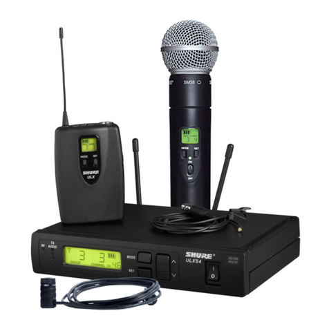
Shure UC1 Owner's manual

CONTENTS
SPECIFICATIONS 2. . . . . . . . . . . . . . . . . . . . . . . . . . . . . . . . . . . . . . . . . . . . . . . .
Furnished Accessories 4. . . . . . . . . . . . . . . . . . . . . . . . . . . . . . . . . . . . . . . . .
Optional Accessories 5. . . . . . . . . . . . . . . . . . . . . . . . . . . . . . . . . . . . . . . . . . .
Replacement Parts 5. . . . . . . . . . . . . . . . . . . . . . . . . . . . . . . . . . . . . . . . . . . . .
FREQUENCY SELECTION GUIDE 6. . . . . . . . . . . . . . . . . . . . . . . . . . . . . . . . . .
Compatibility Groups 6. . . . . . . . . . . . . . . . . . . . . . . . . . . . . . . . . . . . . . . . . . .
Compatible Frequency List 7. . . . . . . . . . . . . . . . . . . . . . . . . . . . . . . . . . . . . .
UHF TV Channel Guide (for U.S. Channels 66–69) 8. . . . . . . . . . . . . . . . .
UC Wireless System
USER GUIDE SUPPLEMENT UA (782–806 MHz)
27C8636 (Rev. 3)
E2003, Shure Incorporated Printed in U.S.A.

2
SPECIFICATIONS
RF Carrier Frequency Range
782–806 MHz
Working Range
152.4 m (500 ft), minimum, under typical conditions; 487.6 m (1600 ft ) line of sight
NOTE: Actual working range depends on RF signal absorption, reflection and inter-
ference.
Audio Frequency Response
45 to 15,000 Hz, ±2 dB.
NOTE: Overall system frequency response depends on the microphone element.
Gain Adjustment Range
UC1: –6 to 34 dB
UC2: –6 to 26 dB
Modulation
±45kHz deviation compressor-expander system with pre-and de-emphasis
RF Power Output
UC1, UC2: 50 mW, typical
Dynamic Range
>100 dB, A-weighted
Receiver Audio Output Level (Maximum)
+5 dBu typical, unbalanced output
+14 dBu typical, balanced output
RF Sensitivity
UC4: –108 dBm at 12 dB SINAD
Image Rejection
90 dB typical
Spurious Rejection
70 dB typical
Ultimate Quieting (ref. 45 kHz deviation)
>100 dB, A-weighted
Audio Polarity
Positive pressure on microphone diaphragm (or positive voltage applied to tip of
WA302 phone plug) produces positive voltage on pin 2 with respect to pin 3 of
low impedance output and the tip of the high impedance 1/4-inch output.
System Distortion (ref. ±45 kHz deviation, 1 kHz modulation)
0.4% Total Harmonic Distortion typical
Power Requirements
UC1, UC2: 9V alkaline battery (Duracell MN1604 recommended); Nicad optional
UC4: 15 Vdc , 600 mA 50/60 Hz
Power Consumption: 600 mA x 15 V, maximum
Transmitter Battery Life (Typical)
8 hours (with Duracell MN1604 9V alkaline battery)
Operating Temperature Range
-7°to 49°C (20°to 120°F)
NOTE: Battery characteristics may limit this range.
Overall Dimensions
UC1: 99.06 mm L x 63.50 mm W x 22.86 mm D (3–29/32 L x 2–1/2 W x 29/32 in. D)
UC2/58:247.30 mm L x 50.8 mm Dia. (9–1/2 L x 2 in. Dia.)
UC2/BETA 58: 241.30 mm L x 50.80 mm Dia. (9–1/2 L x 2 in. Dia.)
UC2/87:215.90 mm x 50.80 mm Dia. (8–1/2 L x 2 in. Dia.)
UC2/BETA 87: 215.90 mm L x 50.8 mm Dia. (8–1/2 L x 2 in. Dia.)
UC4: 44.50 mm H x 197.40 mm W x 214.30 mm D (1–3/4 L x 7.77 W x 8.44 in. D)

3
Net Weight
UC1: 73.50 g (2.59 oz.) without battery
UC2/58, U2/BETA 58: 311.9 g (11 oz.) without battery
UC2/87, U2/BETA 87: 198.5 g (7 oz.) without battery
UC4: 1.22 kg (2 lbs, 11 oz.)
Certification
UC1, UC2: Type Accepted under FCC Parts 74. Certified by IC in Canada under RS 123.
UC4: UL and cUL Listed to UL 813 and CSA C22.2 No. 1. VDE Certified to EN 60 950.
Approved under the DoC provision of FCC Part 15; Certified by IC in Canada under
RS 123.
UC1 Transmitter Input (Figure 1)
Connector: 4-Pin female miniature connector (TA4F) or
LEMO connector (optional)
Input Configuration: Unbalanced, active
Actual Impedance: 18 kΩwith lavalier microphone
1 MΩwith instrument cable
Maximum Input Level: 9 Vp–p (10 dBV) for 1% THD at minimum gain
setting using 1 kHz signal.
Miniature ConnectorTA4F Pin
Assignments:
Pin 1: Tied to Ground
Pin 2: Tied to +5 V
Pin 3: Tied to Audio
Pin 4: Tied thru 20 kΩResistor to Ground.
(On instrument adapter cable, Pin 4 floats)
LEMO Connector
Pin Assignments:
Pin 1: Tied to Pin 3 and 10 kΩ to Ground
Pin 2: +5V
Pin 3: Tied to Pin 1
Pin 4: Tied to Shield (Ground for Positive Bias)
Volt age for Remot e Power: +5 V supplied to microphone cartridge
27 pF
20K Ω
27 pF
+5 V
AUDIO
GROUND
UC1 MIC JACK BOARD
2
1
4
500 Ω
500 Ω
MICRO-
PHONE ELE-
MENT
3
2
1
3
4
NOTE: LAVALIER MIC TIES PINS 3 AND 4 TOGETHER; GUITAR CABLE DOES NOT.
27 pF
499 Ω
499 Ω
3
27 pF
10K Ω
AUDIO
SHIELD
1
4
2BIAS
UC1
UC1L (LEMO 4 PIN) MIC JACK BOARD
FIGURE 1

4
UC1 Transmitter Output
Antenna: Flexible 1/4 wave wire
Actual Impedance: 50 Ω
Nominal Output Level: +16 dBm
Maximum Output Level: +17 dBm
UC2 Transmitter Input
Input Configuration: Unbalanced, active
Actual Impedance: 25 kΩ
Maximum Input Level: 9 Vp–p (10 dBV) for 1% THD at minimum gain setting
using 1 kHz signal.
UC2 Transmitter Output
Antenna: Internal dipole
Actual Impedance: 50 Ω
Nominal Output Level: +16 dBm
Maximum Output Level: +17 dBm
UC4 Receiver Input
Connector: Antenna Power Input
Connector Type: BNC dc style
Actual Impedance: 50 Ω––
Nominal Input Level: –95 to –30 dBm 15 Vdc
Maximum Input Level: +6 dBm
(–20 dBm recommended)
17 Vdc
Pin Assignments: Shell = Ground
Center = Signal
Center pin positive
UC4 Receiver Output
Connector: High Z Audio Low Z Audio
Output Configuration: Unbalanced Balanced
Actual Impedance: 1 kΩ44 Ω
Nominal Input Level: –– ––
Output Level: 5 dBu maximum 14 dBu maximum
Pin Assignments: Tip = Audio +
Ring/ Sleeve = Ground
1 = Ground
2 = Audio +
3 = Audio –
FURNISHED ACCESSORIES
Microphone Stand Adapter (UC2) WA370A. . . . . . . . . . . . . . . . . . . . . . . . . . . . . . . . . . . . .
Zipper Bag (UC1) 26A13. . . . . . . . . . . . . . . . . . . . . . . . . . . . . . . . . . . . . . . . . . . . . . . . . . . . .
Zipper Bag (UC2) 26A14. . . . . . . . . . . . . . . . . . . . . . . . . . . . . . . . . . . . . . . . . . . . . . . . . . . . .
Screwdriver 80A498. . . . . . . . . . . . . . . . . . . . . . . . . . . . . . . . . . . . . . . . . . . . . . . . . . . . . . . . .
1/4 Wave Antenna UA400. . . . . . . . . . . . . . . . . . . . . . . . . . . . . . . . . . . . . . . . . . . . . . . . . . .

5
OPTIONAL ACCESSORIES
Instrument Adapter Cable (UC1) WA302. . . . . . . . . . . . . . . . . . . . . . . . . . . . . . . . . . . . . . .
4–Pin Female Miniature Connector, TA4F (UC1) WA330. . . . . . . . . . . . . . . . . . . . . . . . .
In-Line Audio Switch (UC1) WA360. . . . . . . . . . . . . . . . . . . . . . . . . . . . . . . . . . . . . . . . . . .
1.8 Meter (6 ft) Receiver-Mixer Cable (1/4” phone to XLR) WA410. . . . . . . . . . . . . . . . . .
0.6 Meter (2 ft.) Antenna Extension Cable UA802. . . . . . . . . . . . . . . . . . . . . . . . . . . . . . .
7.6 Meter (25 ft) Antenna Extension Cable UA825. . . . . . . . . . . . . . . . . . . . . . . . . . . . . .
15.2 (50 ft) Meter Antenna Extension Cable UA850. . . . . . . . . . . . . . . . . . . . . . . . . . . . .
Antenna/Power Distribution System, 120 Vac UA845UA. . . . . . . . . . . . . . . . . . . . . . . . . .
Remote Mute Switch for UC1 UA101. . . . . . . . . . . . . . . . . . . . . . . . . . . . . . . . . . . . . . . . . .
Passive Antenna Splitter/Combiner UA220. . . . . . . . . . . . . . . . . . . . . . . . . . . . . . . . . . . . .
1/2 Wave Omnidirectional Antenna for UC4 Receiver UA820A. . . . . . . . . . . . . . . . . . . .
Remote Mount Antenna Kit UA500. . . . . . . . . . . . . . . . . . . . . . . . . . . . . . . . . . . . . . . . . . .
Front Mount Antenna Kit UA600. . . . . . . . . . . . . . . . . . . . . . . . . . . . . . . . . . . . . . . . . . . . . .
REPLACEMENT PARTS
Hardware Kit (screwdriver, mounting feet, cable clamps) 90VX1371. . . . . . . . . . . . . . .
Bulkhead Adapters for Front–Mounting Antennas 95A8647. . . . . . . . . . . . . . . . . . . . . . .
15 Vdc Power Cord (120 VAC) PS40. . . . . . . . . . . . . . . . . . . . . . . . . . . . . . . . . . . . . . . . . .
SM58Cartridge with Grille (UC2/58) R158. . . . . . . . . . . . . . . . . . . . . . . . . . . . . . . . . . . . .
BETA 58ACartridge with Grille (UC2/BETA 58) R179. . . . . . . . . . . . . . . . . . . . . . . . . . .
SM87 Cartridge with Grille (UC2/87) R165. . . . . . . . . . . . . . . . . . . . . . . . . . . . . . . . . . . . . .
BETA 87A Cartridge with Grille (UC2/BETA 87A) R166. . . . . . . . . . . . . . . . . . . . . . . . . . .
BETA 87C Cartridge with Grille (UC2/BETA 87C) RPW100. . . . . . . . . . . . . . . . . . . . . . . .
Matte Silver Grille (UC2/58) RK143G. . . . . . . . . . . . . . . . . . . . . . . . . . . . . . . . . . . . . . . . . .
Matte Silver Grille (UC2/BETA 58) RK265G. . . . . . . . . . . . . . . . . . . . . . . . . . . . . . . . . . . . .
Matte Silver Grille (UC2/BETA 87A) RK313G. . . . . . . . . . . . . . . . . . . . . . . . . . . . . . . . . . .
Black Grille (UC2/87C) RK214G. . . . . . . . . . . . . . . . . . . . . . . . . . . . . . . . . . . . . . . . . . . . . .
Black Grille (UC2/BETA 58) RK323G. . . . . . . . . . . . . . . . . . . . . . . . . . . . . . . . . . . . . . . . . .
Black Grille (UC2/BETA 87A) RK324G. . . . . . . . . . . . . . . . . . . . . . . . . . . . . . . . . . . . . . . . .
Belt Clip (UC1) 44A8013. . . . . . . . . . . . . . . . . . . . . . . . . . . . . . . . . . . . . . . . . . . . . . . . . . . . .
Mounting Brackets, Long 53A8458. . . . . . . . . . . . . . . . . . . . . . . . . . . . . . . . . . . . . . . . . . . .
Mounting Brackets, Short 53A8454. . . . . . . . . . . . . . . . . . . . . . . . . . . . . . . . . . . . . . . . . . . .
Mounting Brackets, Link 31A8138. . . . . . . . . . . . . . . . . . . . . . . . . . . . . . . . . . . . . . . . . . . . .
UC4 Logic Connector (Phoenix) 95A8580. . . . . . . . . . . . . . . . . . . . . . . . . . . . . . . . . . . . . .
6
FREQUENCY SELECTION GUIDE
The Shure UC Wireless System is designed for maximum flexibility and versatility
in a variety of applications. Up to 16 Shure UHF Wireless Systems can be operated
simultaneously in a single installation using the frequency compatibility groups.
Please contact the Shure Customer Service Department if you need additional infor-
mation or assistance in frequency selection and setup.
Compatibility Groups
The Shure UC Wireless System includes 10 groups of compatible channels. If you are
using more than one receiver in the same area, we recommend that you set the receivers
to different frequencies within the same group.
Use frequencies from Groups 0–3, 8, or 9 in locations where TV channels 66, 67, 68,
and 69 are NOT in use. If any of these TV channels are present in your location, use fre-
quencies from one of the Groups 4–7 as indicated in the following table. Use the UHF TV
Channel Guide in this supplement to determine which TV channels may be present in
your area.
TV CHANNEL
PRESENT
OPEN UHF
CHANNELS
RECOMMENDED UC WIRELESS
FREQUENCY GROUP FREQUENCY
RANGE
None 66 ,67, 68, 69 Groups 0–3; 8, 9
66 67, 68, 69 Group 4 782–788 MHz
67 66, 68, 69 Group 5 788–794 MHz
68 66, 67, 69 Group 6 794–800 MHz
69 66, 67, 68 Group 7 800–806 MHz

7
Compatible Frequency List
The following table lists the frequencies in each of the ten compatibility groups.
GROUP
GRP. 0 GRP. 1 GRP. 2 GRP. 3 GRP. 4 GRP. 5 GRP. 6 GRP. 7 GRP. 8 GRP. 9
TV Channels 66, 67, 68, 69 Open TV
Channel
66
Present
TV
Channel
67
Present
TV
Channel
68
Present
TV
Channel
69
Present
TV Channels 66,
67, 68, 69 Open
0 786.250 805.750 805.750 805.625 805.500 805.125 805.625 799.625 786.000 788.125
1 787.500 782.750 783.125 782.625 788.500 782.625 783.125 782.125 786.750 789.375
2 788.500 783.375 783.750 783.125 789.000 784.250 783.750 783.000 788.375 790.125
C
3 789.125 785.125 784.625 783.875 790.125 785.125 784.750 783.625 789.125 791.375
C4 790.250 786.000 785.750 785.625 790.875 786.375 785.500 784.875 790.500 793.125
H5 791.125 787.250 786.500 787.875 792.250 787.125 786.875 785.875 791.250 793.625
A6 792.500 788.250 788.125 789.125 793.000 794.125 788.750 787.250 793.125 795.125
A
N7 795.500 788.875 788.875 789.875 796.500 795.250 789.750 788.375 796.750 795.625
N
N
8 796.250 790.000 790.250 791.125 798.000 796.875 790.375 789.000 798.125 796.375
N
E
9 797.875 790.875 791.000 792.875 798.750 797.625 791.625 789.875 798.875 798.500
E
L
A 799.000 792.250 792.875 793.375 799.750 799.250 793.125 790.375 800.000 799.875
L
B 800.500 795.250 796.500 794.875 800.500 800.375 800.500 792.875 800.625 801.625
C 801.000 796.000 797.875 795.375 801.875 802.375 801.000 794.125 801.625 802.375
D 802.750 797.625 798.625 796.125 802.500 802.875 801.750 795.625 803.625 803.625
E 803.750 798.750 799.750 798.250 803.500 803.625 803.500 796.375 804.125 805.125
F 805.250 800.250 800.375 799.625 804.250 804.625 804.125 798.125 805.375 805.875

8
UHF TV Channel Guide (for U.S. Channels 66–69)
The following table identifies U.S. cities that have UHF TV stations operating on TV
Channels 66, 67, 68, and 69. Shure recommends that you operate your wireless system
only on TV channels other than those listed for your location.
STATE CITY TV
CHANNEL
STATE CITY TV
CHANNEL
Alabama Birmingham 68 Michigan East Lansing 69
Opelika–Auburn 66 Flint 66
Troy 67 New Jersey Newark 68
California Los Angeles 68 West Milford 66
Salinas–
Monterrey
67 New York Ilion 67
Novato 69 Smithtown 67
San Diego 69 Springville 67
Vallejo 66 Syracuse 68
Florida Bradenton 66 North Carolina Bryson City 67
Cocoa 68 Forest City 66
Hollywood 69 High Point 67
Lake Worth 67 Ohio Canton 67
Georgia Atlanta 69 Mansfield 68
Toccoa 68 Springfield 66
Hawaii Lihue 67 Pennsylvania Allentown 69
Illinois Danville 68 Erie 66
Elgin 66 Rhode Island Block Island 69
Galesburg 67 South Dakota Lowry 68
Joliet 66 Tennessee Lebanon 66
Indiana Anderson 67 Texas Alvin 69
Indianapolis 69 Arlington 68
Iowa Des Moines 69 Virginia Fredericksburg 69
Kentucky Louisville 68 Grundy 68
Morehead 67 Manassas 66
Paintsville 69 Washington Olympia 67
Maryland Baltimore 67 Wisconsin Fond du Lac 68
Hagerstown 68 West Virginia Fairmont 66
Massachussets Boston 68 Puerto Rico Humacoa 68
Marlborough 66
SHURE Incorporated Web Address: http://www.shure.com
5800 W. Touhy Avenue, Niles, IL 60714-4608, U.S.A.
Phone: 800-257-4873 Fax: 847-600-1212
In Europe, Phone: 49-7131-72140 Fax: 49-7131-721414
In Asia, Phone: 852-2893-4290 Fax: 852-2893-4055
Elsewhere, Phone: 847-600-2000 Fax: 847-600-6446
This manual suits for next models
6
Table of contents
Other Shure Microphone System manuals

Shure
Shure SLX-D User manual

Shure
Shure BLX4R User manual

Shure
Shure DuraPlex DH5 User manual

Shure
Shure Unf-R User manual

Shure
Shure GLXD4 User manual

Shure
Shure UA User manual

Shure
Shure BLX4R T11 User manual

Shure
Shure MX890 User manual

Shure
Shure ULX Wireless System User manual

Shure
Shure GLX-D User manual

Shure
Shure BLX Wireless System User manual

Shure
Shure MXW User manual

Shure
Shure T series User manual

Shure
Shure MXA-MUTE User manual

Shure
Shure PA421SWB User manual

Shure
Shure SLX Wireless System User manual

Shure
Shure MXW Series User manual

Shure
Shure M4 Owner's manual

Shure
Shure MX690 User manual

Shure
Shure LX Wireless System User manual