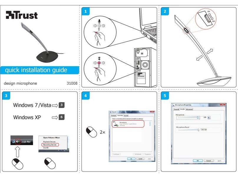
Shure Microflex Advance MXA910 User manual

1/87
MXA910 -- Ceiling Array Microphone
Overview
General Description
The Microflex Advance™ Ceiling Array is a premium networked array microphone for AV conferencing environ
ments, including boardrooms, huddle rooms, and multi-purpose spaces. Revolutionary technology from the Shure
DSP suite includes Steerable Coverage™, with 8 highly directional pickup lobes that capture participant audio
from overhead. Control the microphone with Shure Designer software, or a browser-based web application. The
microphone integrates seamlessly with Dante™ digital networked audio and thirdparty preset controllers, includ
ing Crestron and AMX, to deliver a high-quality AV conferencing experience that appeals equally to integrators,
consultants, and meeting participants.
®

Shure Incorporated
2/87
Features
Configurable Coverage
•Steerable Coverage delivers precise pickup for up to 8 independent lobes
•Shure DSP Suite provides fast-acting automatic mixing, echo reduction, and channel equalization
Software Control
•Shure Designer software provides comprehensive microphone and pattern control
•With Designer, you can also design coverage with online and offline devices, and route audio between Shure
devices
•If Designer isn't available, use the browser-based web application to control the microphone
Network Connectivity
•Discrete audio channels for each lobe and an automix channel are delivered over a single network cable
•Dante digital audio coexists safely on the same network as IT and control data, or can be configured to use a
dedicated network
•Control strings available for third-party preset controllers including Crestron and AMX

Shure Incorporated
3/87
Professional Design
•Sleek industrial design blends with contemporary board rooms and meeting spaces
•Seamless flush-mount with standard ceiling tiles
•Available in white, black, and aluminum finishes (detachable grille can be custom painted)
System Overview
①Dante audio, power, and control
Each array microphone connects to the network over a single network cable, which carries Dante audio, Power
over Ethernet (PoE), and control information to adjust coverage, audio levels, and processing.
②Analog audio (microphone to network)
Analog equipment, such as a wireless microphone system or a gooseneck microphone on a podium, connects to
the Dante audio network through a Shure Network Interface (model ANI4IN) for a completely networked confer
encing system.
③Far-end audio (network to loudspeakers)
Danteenabled loudspeakers and amplifiers connect directly to a network switch. Analog loudspeakers and ampli
fiers connect through a Shure Network Interface (model ANI4OUT), which converts Dante audio channels into
analog signals, delivered through 4 discrete XLR or block connector outputs.
④Device control and Dante audio
Control: A computer connected to the network controls the microphone with Shure Designer software. You can re
motely adjust coverage, muting, LED behavior, lobe settings, gain, and network settings.
Audio: Route audio with Dante™ Controller or Shure Designer software. Dante Virtual Soundcard enables audio
monitoring and recording directly on the computer.

Shure Incorporated
4/87
System Planning and Gear Requirements
Setting up the Audio Network
Shure networked conferencing systems are comprised of Microflex Advance microphones and network interfaces,
which operate entirely on a Dante network. Additional hardware, including network switches, computers, loud
speakers, and audio processors are described in the hardware component index.
Shure components shown in this diagram:
Microflex Advance Microphones
The MXA910 and MXA310 are equipped with Dante outputs, and connect directly to a network switch.
Audio Network Interfaces
The interfaces are used to connect analog devices such as loudspeakers and analog microphones to the network.
ANI4IN: Converts 4 analog signals (separate XLR and block connector models available) into Dante digital audio
signals.
ANI4OUT: Converts 4 channels of Dante audio from the network into analog signals.
This diagram shows the entire signal path through a networked conference system. Signals from the near end and
far end are exchanged through an audio processor connected to a phone system, or through a computer connect
ed to the internet. Analog microphones connect to the network through the Shure ANI4IN, while loudspeakers con
nect through the Shure ANI4OUT.

Shure Incorporated
5/87
This diagram shows Microflex Advance components in context, with two rooms communicating through video
codecs.
Controlling Hardware and Audio Over the Network
Audio and hardware settings are managed through a computer connected to the same network.
Shure Hardware and Audio
Each Microflex Advance component has a web application which provides mixing and configuration tools to opti
mize sound quality.
Expanded Control for Analog Devices
Analog devices that are connected to the network through a Shure network interface (ANI4IN/ANI4OUT) benefit
from additional remote control: Volume levels, equalization, and signal routing are managed through the web appli
cation. For example, adjusting loudspeaker volume or muting a wired microphone, which would normally be done
from the hardware, can now be controlled remotely over the network.
Dante Signal Routing
You can manage signal routing with Dante Controller or Shure Designer software.

Shure Incorporated
6/87
Hardware Component Index
Network Switch
The network switch provides central connectivity for
all networked components. Audio from any networked
Shure microphones that are connected to the switch
can be routed to any Dante-enabled device. The
switch sends and receives audio and control data,
while simultaneously powering the microphones and
audio network interfaces through PoE (Power over
Ethernet). See the network switch requirements () for
additional details.
Power over Ethernet (PoE) Requirements:
All Shure components included in these scenarios re
quire Power over Ethernet (class 0). If not provided
through the network switch, a PoE injector is required
to power the devices.
Shure Microflex Wireless Audio Network Interface (MXWANI)
The Microflex Wireless Audio Network Interface
(MXWANI) is a digital-to-analog breakout box with a
built-in gigabit network switch. It converts digital audio
from the network into analog signals for signal pro
cessing or amplification, and provides PoE over one
network port to power a device. For details, refer to
the Microflex Wireless user guide, available at http://
www.shure.com.
Audio Processor

Shure Incorporated
7/87
The audio processor sends and receives audio
through a VOIP server or a standard phone line. They
also provide digital signal processing, such as
acoustic echo cancellation.
Danteen
abled
Processors that support Dante con
nect directly to the network switch to
receive audio from Microflex Advance
microphones.
Analog When using an analog processor, a
converter (such as the Shure
ANI4OUT or MXWANI) is required to
deliver the analog audio from Mi
croflex Advance microphones to the
processor.
Video Codec
Like the audio processor, the codec sends and re
ceives audio signals alongside video signals between
the near end and the far end. Audio from the near end
must connect to the audio input on the video codec,
which is typically a stereo analog connection. The
Shure ANI4OUT Audio Network Interface converts the
audio to an analog signal for connecting to a codec.
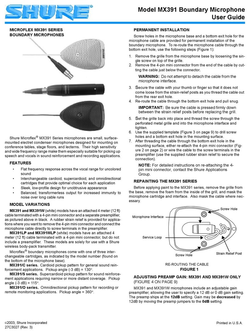
Shure ANI4IN Audio Network Interface (Analog-to-Dante Converter)
The Shure ANI4IN Audio Network Interface converts 4
channels of analog audio into independent digital au
dio channels on a Dante network. Adjustable gain and
+48V phantom power deliver the flexibility to support
line, auxiliary, and microphonelevel devices. For net
worked conferencing systems, the Audio Network In
terface provides a simple way to connect previously
installed analog equipment onto the audio network,
such as wireless microphones for presenters. The
web application gives technicians and administrators
control over channel levels and settings from any
computer connected to the same network.
Shure ANI4OUT Audio Network Interface (Dante-to-Analog Converter)
Shure Incorporated
8/87
The Shure ANI4OUT Audio Network Interface con
verts 4 channels of Dante digital audio into discrete
analog signals. Available in both XLR and block con
nector versions, each box uses a single network cable
to receive audio and power using Power over Ethernet
(PoE). The web application gives technicians and ad
ministrators control over channel levels and settings
from any computer connected to the same network.
Amplifiers and Loudspeakers
Audio from the far end is routed to local loudspeakers.
Dante-enabled speakers or amplifiers connect directly
to the network switch, while analog systems require
an audio network interface to receive networked au
dio.
Computers and Control Systems
Browser-
Based
Web Ap
plication
A computer connected to the network
provides control of Shure networked
components through the web applica
tion for each device.
Dante
Software
A computer running Dante Virtual
Soundcard, Dante Controller, and
web conferencing software is used to
send and receive audio between the
near end and far end.
Control
Systems
(AMX,
Crestron,
etc.)
If using a third-party control system,
Microflex Advance microphones send
and receive commands over Ether
net. If an analog logic signal must be
sent over the network, the Shure
ANI4IN Audio Network Interface re
ceives analog logic signals and con
verts them into Ethernet control
strings.
System Use Cases
These use cases will help you understand how Shure devices fit in conference rooms, huddle rooms, and multi
purpose spaces.

Shure Incorporated
9/87
Each diagram includes:
•Signal flow and connections
•Required devices
Power Over Ethernet and Hardware Requirements
All Shure devices included in these use cases require Power over Ethernet (PoE, class 0). Refer to the Dante
and Networking section for additional information on cable and network switch requirements.
Telephone Conference with Shure MXW Network Interface

Shure Incorporated
10/87
①Array microphone to Shure MXWANI
Connect the microphone output to port 1 on the MXWANI with a network cable. Port 1 provides the necessary
Power over Ethernet (PoE).
②Computer to Shure MWXANI
Connect a computer to the ANI on port 2 or 3 with a network cable to provide control of the array microphone and
other networked components.
③Shure ANI analog outputs to audio processor
Step 1: Route signals with Dante Controller software
Route the channels from the microphone (Dante transmitter) to the MXWANI channels (Dante receiver). This es
tablishes the discrete channels to deliver through the analog outputs.
Step 2: Connect the MXWANI outputs to the processing device inputs
Block connector outputs on the MXWANI send balanced audio signals to the inputs on the processing device,
which provides digital signal processing (such as acoustic echo cancellation).
④Connection to far end
Connect the audio processor to a VOIP server or telephone line to send and receive audio between the near end
and far end.
⑤Audio from far end to amplifier
Route the far end audio through the audio processor output to an amplifier.
⑥Amplified audio signal to loudspeakers
Connect the loudspeakers to the amplifier to hear the audio from the far end.

Shure Incorporated
11/87
Telephone Conference with Dante-enabled Audio Processor
①Array microphone to network switch
Connect the array microphone output with a network cable to any port on the switch that supplies Power over Eth
ernet (PoE).
②Computer to network switch
Connect a computer to the network switch to provide control of the array microphone and other networked compo
nents.
③Network switch to Dante audio processor

Shure Incorporated
12/87
Connect the Dante audio processor to the network switch to provide:
•Digital signal processing (acoustic echo cancellation)
•Digital-to-analog conversion to deliver Dante audio over an analog (VOIP or telephone line) output.
•Analog-to-digital conversion to deliver analog audio from the far end onto the Dante network.
④Connection to far end
Connect the output from the audio processor to a VOIP server or telephone line to deliver audio between the near
end and far end.
⑤Audio from far end to amplifier
Route the far end audio through the audio processor output to an amplifier.
⑥Amplified audio signal to loudspeakers
Connect the loudspeakers to the amplifier to deliver the audio from the far end.

Shure Incorporated
13/87
Telephone Conference with Network Interfaces and Audio Processor
①Array microphone to network switch
Connect the array microphone output with a network cable to any port on the switch that supplies power over eth
ernet (PoE).
②Computer to network switch
Connect a computer to the network switch to provide control of the array microphone and other networked compo
nents through the software control panel.

Shure Incorporated
14/87
③ANI4OUT (digital-to-analog conversion)
From the network switch: Use network cables to connect each ANI4OUT to the network switch. A single
ANI4OUT receives 4 channels of Dante audio, and converts them to 4 analog signals, delivered through XLR out
puts or block connectors. Using two of them, all 8 channels from the array microphone can be connected to analog
inputs on an audio processing device.
To a processing device: Route the ANI4OUT outputs to the processing device inputs to provide digital signal pro
cessing (acoustic echo cancellation).
④Connection to far end
Connect the output from the audio processor to a VOIP server or telephone line to deliver audio between the near
end and far end.
⑤Audio from far end to amplifier
Route the far end audio through the audio processor output to an amplifier.
⑥Amplified audio signal to loudspeakers
Connect the loudspeakers to the amplifier to deliver the audio from the far end

Shure Incorporated
15/87
Web Conferencing Software With Dante Virtual Soundcard
①Array microphone to network switch

Shure Incorporated
16/87
Connect the array microphone output with a network cable to any port on the switch that supplies Power over Eth
ernet (PoE).
②Computer to network switch
Connect a computer to the network switch to control the array microphone and other networked components. The
computer also runs Dante Virtual Soundcard, Dante Controller, and the web conferencing software.
•Dante Virtual Soundcard / Controller: Turn on the Dante Virtual Soundcard and use Dante Controller to route
the array microphone signal to the computer.
•Web Conferencing Software:Assign the audio input and output device settings to the appropriate Dante trans
mitter and receiver channels.
③Network switch to ANI4OUT
Use network cables to connect each ANI4OUT to the network switch. Each interface receives 4 channels of Dante
audio, and converts them to 4 analog signals, delivered through XLR outputs or block connectors.
④Audio from far end to amplifier
Route the far-end audio to an amplifier.
⑤Amplified audio signal to loudspeakers
Connect the loudspeakers to the amplifier to deliver the audio from the far end.

Shure Incorporated
17/87
Video Conference
①Array microphone to network switch
Connect the array microphone output with a network cable to any port on the switch that supplies power over eth
ernet (PoE).
②Computer to network switch

Shure Incorporated
18/87
Connect a computer to the network switch to provide control of the array microphone and other networked compo
nents through the software control panel.
③ANI4OUT (digital-to-analog conversion)
Each ANI4OUT receives 4 channels of Dante audio, and converts them to 4 analog signals, delivered through XLR
outputs or block connectors.
Input: Connect the ANI4OUT to the network switch with a network cable
Ouput: Connect the analog output to the audio input on the video codec
④Video codec connection to far end
Connect the codec to the appropriate network to connect with the far end.
⑤Audio from far end to amplifier
Route the far end audio through the video codec audio output to an amplifier.
⑥Amplified audio signal to loudspeakers
Connect the loudspeakers to the amplifier to deliver the audio from the far end.
Hardware
Network Ethernet Port
The network port carries all audio, power, and control data. It is located on the back panel as shown.
①Network Port
RJ-45 jack for network connection.
②Network Status LED (Green)
Off = no network link
On = network link established
Flashing = network link active

Shure Incorporated
19/87
③Network Speed LED (Amber)
Off = 10/100 Mbps
On = 1 Gbps
LED Light Bar
The LED on the microphone indicates whether the microphone is active or muted, identifies the hardware, and
provides confirmation of firmware updates.
Default Settings
Microphone Status LED Behavior / Color
Active Green (solid)
Mute Red (solid)
Hardware identification Green (flashing)
Firmware update in progress Green (progresses along bar)
Reset Network reset: Red (progresses along bar)
Factory reset: Triggers device power-up
Error Red (split, alternate flashing)
Device power-up Multi-color flash, Blue (moves quickly back and forth
across bar)

Shure Incorporated
20/87
Note: When the LED is disabled, the LED still illuminates while the device is powering up and when an error state
occurs.
Customizing Lighting Settings
Custom LED brightness, colors, and behaviors are assignable in the control software. They can also be controlled
through an external control system:
1. Open the Configuration tab
2. Select Light Bar
Mute LED Behavior
The lighting for mute and active microphone states is configurable to match the behavior of other devices in con
ference rooms. In the LIGHT BAR PROPERTIES menu, use the drop-down menus to select LED settings.
Dimming and Disabling
To dim or turn off the LED, use the drop-down menu in the Light Bar configuration screen.
Reset Button
The hardware reset button is located inside a grille hole and can be pushed with a paperclip or other small tool.
The hole is identified with a gray circle. When looking at the Shure logo, it is the second hole in the fourth row from
the top.
Reset Modes
Network reset (press button for 4-8 seconds)
Resets all Shure control and audio network IP settings to factory defaults.
Full factory reset (press button for longer than 8 seconds)
Restores all network and web application settings to the factory defaults.
Software Reset Options
To simply revert settings without a complete hardware reset, use one of the following options:
Other manuals for Microflex Advance MXA910
3
Table of contents
Other Shure Microphone manuals

Shure
Shure 520DX User manual

Shure
Shure STARMAKER SM77 User manual

Shure
Shure PGA 52 User manual

Shure
Shure BETA53 User manual

Shure
Shure Controlled Magnetic 444D User manual

Shure
Shure 545SD User manual

Shure
Shure Microflex MX418D User manual

Shure
Shure 407A User manual

Shure
Shure PGA27 User manual

Shure
Shure Unidyne B 515BG User manual

Shure
Shure KSM32 User manual

Shure
Shure 515SDX User manual

Shure
Shure 545D User manual

Shure
Shure BG 1.0 User manual

Shure
Shure VP83F User manual

Shure
Shure MV88+ User manual

Shure
Shure Spher-O-Dyne 533SA User manual

Shure
Shure SM7B User manual

Shure
Shure RK6MB User manual

Shure
Shure Microflex MX400SE Series User manual